Download presentation
Presentation is loading. Please wait.

1
T ROOPER W. S MITH, P.E. F REESE AND N ICHOLS, I NC. 10814 J OLLYVILLE R D., B LDG 4, S UITE 100 A USTIN, TX 78759 MINIMIZE YOUR FOOTPRINT AND YOUR MAINTENANCE HEADACHES SELF CLEANING TRENCH TYPE WET WELL DESIGNS

2
PRESENTATION OBJECTIVES Story Time - Pump Station 13B Introduction to Trench Type Wet Wells Introduction to Self Cleaning Operation Would the design be right for you?

3
Trinity River Authority – CRWS Treatment Plant Design and Construction of Pump Station 13B Fluid of Interest: Return Activated Sludge – Final Clarifiers – Traveling Bridge Suction Clarifiers – Thin Sludge Firm Capacity – 200 MGD for WWTP – Downrated PS-13 – 50 MGD (North Plant, Trains 1-3) – New PS-13B – 50 MGD (North Plant, Trains 4-6) – Uprated PS-13A – 100 MGD (South Plant, Trains 7-12) PROJECT SCOPE
 – New PS-13B – 50 MGD (North Plant, Trains 4-6) – Uprated PS-13A – 100 MGD (South Plant, Trains 7-12) PROJECT SCOPE")
5
13A 13 13B

6
FEASABILITY REPORT PRELIMINARY DESIGN REPORT FINAL DESIGN CONSTRUCTION PHASE HISTORY OF THE PROJECT YEAR 2005 YEAR 2006 YEAR 2007 YEAR 2007 TO 2009

7
1. Presentation Objectives2. Project Background3. Pump Station Evaluation4. Trench Type Wet Well5. Construction Photos6. Acknowledgements/Questions TOPIC

8
Dry-Pit/Wet-Pit – Horizontal Non-Clog Centrifugal Pumps (PS-13 and PS-13A) – Vertical Non-Clog Centrifugal Pumps (PS-6 and PS-6A) Wet-Pit – Vertical Turbine Solids Handling Pumps (VTSH) PUMP STATION EVALUATION
 – Vertical Non-Clog Centrifugal Pumps (PS-6 and PS-6A) Wet-Pit – Vertical Turbine Solids Handling Pumps (VTSH) PUMP STATION EVALUATION")
9
Vertical Non-Clog Centrifugal Pumps (PS-6 and 6A) Pump Station 13A Horizontal Non-Clog Centrifugal Pump (PS-13A)
 Pump Station 13A Horizontal Non-Clog Centrifugal Pump (PS-13A)")
10
VTSH PUMPS

11
City of Phoenix, 23 rd Ave. WWTP (36-inch VTSH Pumps)
")
12
60-inch Final Clarifier Effluent Line 84-inch Primary Clarifier Effluent Line Electrical Duct Bank Caustic Soda Tank 2-inch to 12-inch Lines 12-foot Roadway LIMITATIONS AT PS-13B SITE Existing Structures and Utilities

13
DRY PIT VERSUS WET PIT Relocated 84-inch PCE Line Relocated Caustic Soda Building Relocated Pavement Relocated 60-inch FCE Line Footprint of Dry-Pit/Wet-Pit (Horizontal Non-Clog Pumps)
")
14
Existing Caustic Soda Storage Facility, 84-inch PCE Line, 60-inch FCE Line and Pavement Remains Unchanged Footprint of Wet-Pit Wet Well (VTSH Pumps)
")
15
Pump Station Type Length/WidthDepthPump Cost ($)*OPCC ($)** Horizontal Non- Clog Centrifugal Pump Station (Wet Pit/Dry Pit) 67’/65’26’’$915,000$10.9 million Vertical Non-Clog Centrifugal Pump Station (Wet Pit/Dry Pit) 59’/54’~ 35’$945,000$11.4 million VTSH Pump Station (Wet Pit) 49’/43’29’$1,718,000$9.5 million DRY PIT VS. WET PIT * Total Pump Cost for 3 Pumps ** OPCC: Opinion of Probable Construction Cost

16
1. Presentation Objectives2. Project Background3. Pump Station Evaluation4. Trench Type Wet Well5. Construction Photos6. Acknowledgements/Questions TOPIC

17
TRENCH TYPE WET WELL Illustrative View of Kirkland Pump Station (Washington) Invented by D.H. Caldwell in 1964 Improved by Dr. Robert Sanks, Ph.D., P.E. – 1:1 scale model of portion of trench floor Result: >5 fps requirement – 1:3.3 scale model of the Kirkland Pump Center Result: Only a small portion of the sand was ejected at pump down equilibrium. 1998 Breakthrough – 2 nd Edition of Pumping Station Design – ANSI/HI 9.8 Pump Intake Design

18
ANSI/HI 9.8 Pump Intake Design (1998)
")
19
ANSI/HI 9.8 Pump Intake Design (2012)
")
21
Suitable for Design Flows > 3 MGD Pump Intakes, Confined in a Deep, Narrow Ditch Pump Intakes, Substantially Lower Than Upstream Inlet Pipe TRENCH TYPE WET WELL

22
Suitable for Different Pump Types/Arrangements – Wet Pit or Dry Pit/Wet Pit – Pumps VTSH Submersible Non-Clog Centrifugal Suitable for Different Fluids – Clean Water – Activated Sludge – Raw Wastewater TRENCH TYPE WET WELL Dallas Water Utilities Central WWTP Influent Pump Station (335MGD initial capacity, 425MGD ultimate capacity)
")
23
Advantages – Superb Hydraulic Environment for Pump Intakes – Minimum Footprint Size – Small Floor Area (Minimum accumulation of sludge or grit) – Ease and Quickness of Cleaning – Reduced Disposal of Materials Disadvantages – Compact, Minimal Storage Capacity – Increased Depth – Clogging if Pumps Not Used TRENCH TYPE WET WELL
 – Ease and Quickness of Cleaning – Reduced Disposal of Materials Disadvantages – Compact, Minimal Storage Capacity – Increased Depth – Clogging if Pumps Not Used TRENCH TYPE WET WELL")
24
Pump Station Type Length/WidthDepthPump Cost ($)*Cost ($) Wet-Pit Pump Station 49’/43’29’$1,718,000**$9.5 million Trench Type Wet Well Pump Station 57’/18’38’$1,718,000~$8.5 million WET PIT VS. TRENCH TYPE * Total Pump Cost for 3 Pumps ** OPCC: Opinion of Probable Construction Cost

25
Site Plan – RAS Pump Station 13B

26
Wet Well Plan Elevation at 415.00’ Wet Well TrenchFlow Splitter

27
SECTION VIEWS Flow Splitter Trench Water Guide Fillet Sloping Walls

28
SECTION VIEWS

29
4 fps (wet pit) 3 fps (dry pit) 1 fps max above trench Illustrative Section of Pump Station 13B – Normal Operation
 3 fps (dry pit) 1 fps max above trench Illustrative Section of Pump Station 13B – Normal Operation")
30
SELF CLEANING CYCLE Mixes sludge and scum into a mass that is ejected by the last pump. Cleaning Ramp Trench Hydraulic Jump Pump Down 30-60% Flow Components

31
Illustrative Section of Pump Station 13B – Cleaning Cycle (Pump Down) Cleaning Ramp
 Cleaning Ramp")
32
Illustrative Section of Pump Station 13B – Cleaning Cycle (Pump Down)
")
33
Cleaning Ramp Illustrative Section of Pump Station 13B – Cleaning Cycle (Pump Down)
")
34
Cleaning Ramp Illustrative Section of Pump Station 13B – Cleaning Cycle (Pump Down)
")
36
1. Presentation Objectives2. Project Background3. Pump Station Evaluation4. Trench Type Wet Well5. Construction Photos6. Acknowledgements/Questions TOPIC

37
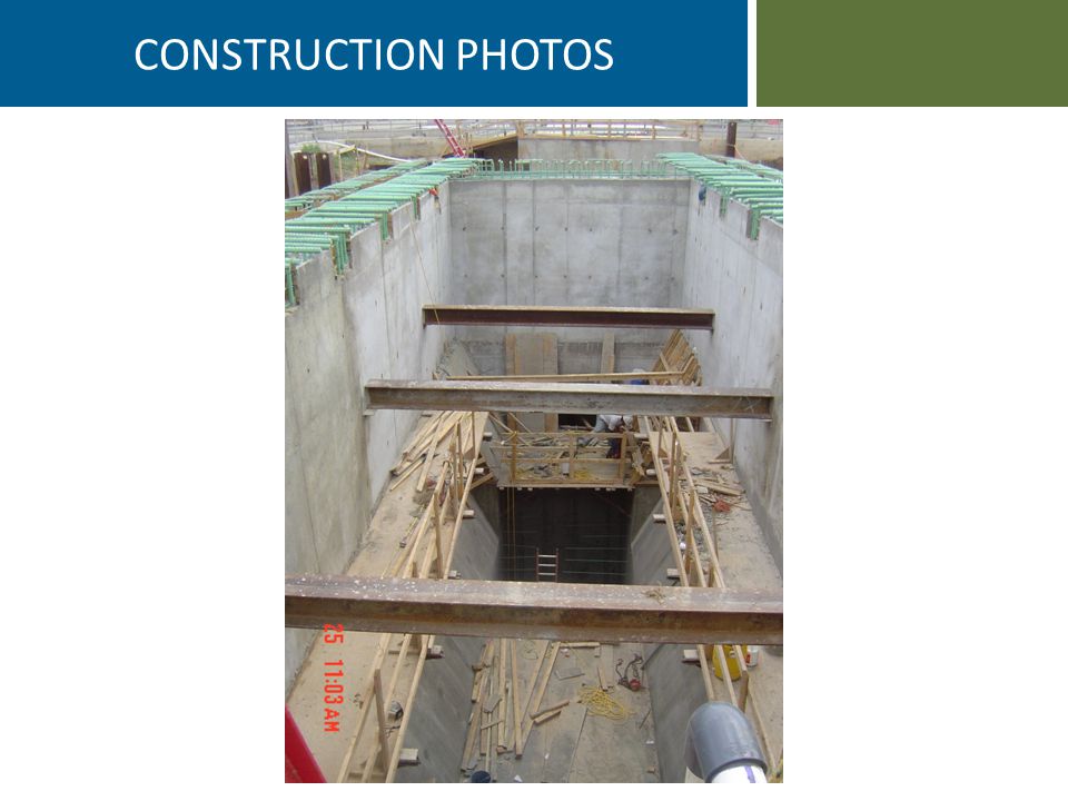
CONSTRUCTION PHOTOS

48
1. Presentation Objectives2. Project Background3. Pump Station Evaluation4. Trench Type Wet Well5. Construction Photos6. Acknowledgements/Questions TOPIC

49
Trinity River Authority of Texas ANSI/HI (Hydraulic Institute) Pump Standards, 1998/2012 Pumping Station Design, 3 rd Edition – Editor-in-Chief: Garr M. Jones, P.E. – Co-Editors: Dr. Robert L. Sanks, Ph.D., P.E. Dr. George Tchobanoglouos, Ph.D., P.E. Bayand E. Bosserman II, P.E. Dr. Robert L. Sanks, Ph.D., P.E. (Quality Control) Dr. Joel E. Cahoon, Ph.D., P.E., Montana State University ACKNOWLEDGEMENTS
 Dr. Joel E. Cahoon, Ph.D., P.E., Montana State University ACKNOWLEDGEMENTS.")
50
Contact Information Trooper Smith tws@freese.com 512-617-3116 CLOSING REMARKS / QUESTIONS Is this the right design for you? – Limited on Space? – Solids/grit problem? – Tired of maintenance intensive cleaning? – Don’t prefer dry-pit/wet-pit? Pre-Design Evaluation – Cost Analysis (Life Cycle) – Benefits Analysis – Reference Calls – Site Visits
 – Benefits Analysis – Reference Calls – Site Visits.")
51
PUMP STATION 13B TESTING 1 clarifier 16 MGD Sluice gate for proper flow rate Use last pump 2-3 clarifiers 32-50 MGD 2 pumps at full speed, let turbulence do the cleaning 2-3 clarifiers 32-50 MGD Sluice gate for proper flow rate Use last pump Scenario 1 Scenario 2A Scenario 2B

Similar presentations


 Prepared by Dr. Richard O. Mines, Jr., P.E. Mercer University Environmental Engineering Department.>")


 Dr. Eng. Ibrahim Khaled El-Sayed Chairman 1North & South Sinai.>")
