Download presentation
Presentation is loading. Please wait.

1
Cardiovascular computerized tomography Basics and evaluation of CAD Frijo Jose A

3
Scanner Generations Third generation most popular since detector geometry is simplest – collimation is feasible which eliminates scattering artifacts FirstSecond Third Fourth

4
1 st generation- 4.5 min/image – series of exposures - X-ray source moved laterally – tube then rotated to a different position - sequence repeated 2 nd generation - 2.5 min/image – fan beam architecture – activate multiple detectors before moving to a new position 3 rd generation - 18 s/image – rotating X-ray source coupled to rotating detectors 4 th generation - 2 s/image – rotating X-ray source with a fixed detector array

5
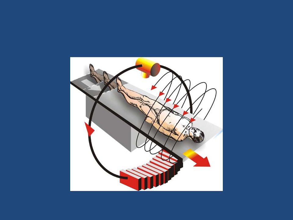
Principle a fan-shaped, thin Xray beam passes through the body at many angles to allow for cross-sectional images The corresponding X-ray transmission measurements are collected by a detector array. The data recorded by the detectors are digitized into picture elements (pixels) with known dimensions. The gray-scale information contained in each individual pixel is reconstructed according to the attenuation of the X- ray beam along its path Gray-scale values for pixels within the reconstructed tomogram are defined with reference to the value for water and are called “Hounsfield units” or simply “CT numbers.”
 with known dimensions. The gray-scale information contained in each individual pixel is reconstructed according to the attenuation of the X- ray beam along its path Gray-scale values for pixels within the reconstructed tomogram are defined with reference to the value for water and are called Hounsfield units or simply CT numbers. .")
6
Cardiac CT Needs both spatial and temporal resolution EBCT has the best temporal resolution, MDCT the best spatial resolution 2 biggest problems - MDCT and EBCT angiography - dense calcifications and stents

7
MDCT Rapidly rotating X-ray tube and several rows of detectors, also rotating The tube and detectors are fitted with slip rings that allow them to continuously move through multiple 360° rotations

8
MDCT v/s single detector-row helical/spiral CT principally by the design of the detector arrays and data acquisition systems, which allow the detector arrays configured electronically to acquire multiple adjacent sections simultaneously

9
Single-slice Multi-slice

10
One of the advantages of MDCT over EBCT is the variability of the mA settings, thus increasing the versatility for general diagnostic CT in nearly all patients and nearly all body segments

11
MDCT modes Sequential mode (prospective triggered) Helical mode (retrospective gating)
 Helical mode (retrospective gating)")
12
Sequential mode

13
Spiral mode

15
Prospective Triggering “step and shoot” system, similar to EBCT obtains images at a certain time of cardiac cycle, which can be chosen in advance, only 1 image/detector/cardiac cycle obtained reduces contrast requirements does not allow for CT angiographic images, as motion artifacts may plague these images

16
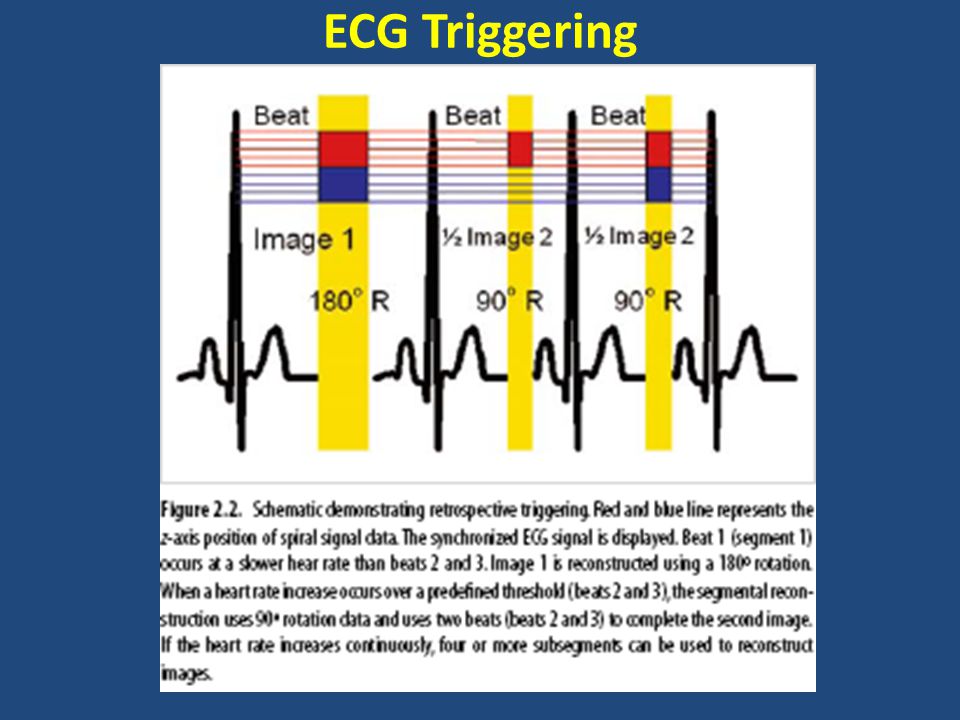
Retrospective Gating A simultaneous ECG recorded during the acquisition of cardiac images The ECG retrospectively used to assign source images to the respective phases of the cardiac cycle (ECG gating) Best imaging time to minimize coronary motion - from 40% - 80% of cardiac cycle (early to middiastole). There is a continuous model of the volume of interest from base to apex Increase in radiation dose

17
EBCT

18
Non-mechanical X-ray source – fixed X-ray source, which consists of a 210° arc ring of tungsten, activated by bombardment from a magnetically focused beam of electrons fired from an electron source “gun” Allows for image acquisition on the order of 50–100ms Prospective ECG triggering

19
Comparisons of EBCT and MDCT Scanners Spatial Resolution X-ray flux Speed/Temporal Resolution Radiation Dose

20
Spatial Resolution Current CAC scanning protocols use 3 mm thickness for EBCT and betw 2.5mm to 3.0mm for MDCT For CT angiography, EBCT utilizes 1.5mm slices, and MDCT most often obtains images with 0.5–0.75 mm per axial slice

21
X-ray flux EBCT limited to 63mAs (100mAs for e-Speed) mAs for MDCT angiography is 300 to 400 MDCT can increase the mAs (and kV) to help with tissue penetration, while EBCT is more limited in this clinical setting
 mAs for MDCT angiography is 300 to 400 MDCT can increase the mAs (and kV) to help with tissue penetration, while EBCT is more limited in this clinical setting")
22
Speed/Temporal Resolution Current CT system images for measuring calcified plaque at 50–100ms (EBCT) and 180–300ms (prospectively gated MDCT) cannot totally eliminate coronary artery motion in all individuals The temporal resolution – determines degree of motion suppression Dependent on – Pitch factor – Gantry rotation time – Patient’s heart rate
 and 180–300ms (prospectively gated MDCT) cannot totally eliminate coronary artery motion in all individuals The temporal resolution – determines degree of motion suppression Dependent on – Pitch factor – Gantry rotation time – Patient’s heart rate")
23
Radiation Dose

24
Clinical Applications-Cardiovasc CT Non-contrast studies can accurately identify and quantify coronary calcification (a marker of total plaque burden) Contrast-enhanced studies can define ventricular volumes,EF, and RWMA and wall thickening Can visualize the coronary artery, including the lumen and wall
 Contrast-enhanced studies can define ventricular volumes,EF, and RWMA and wall thickening Can visualize the coronary artery, including the lumen and wall")
25
ECG Triggering

27
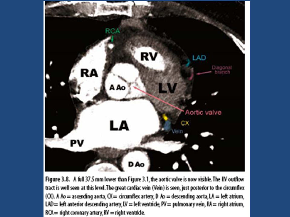
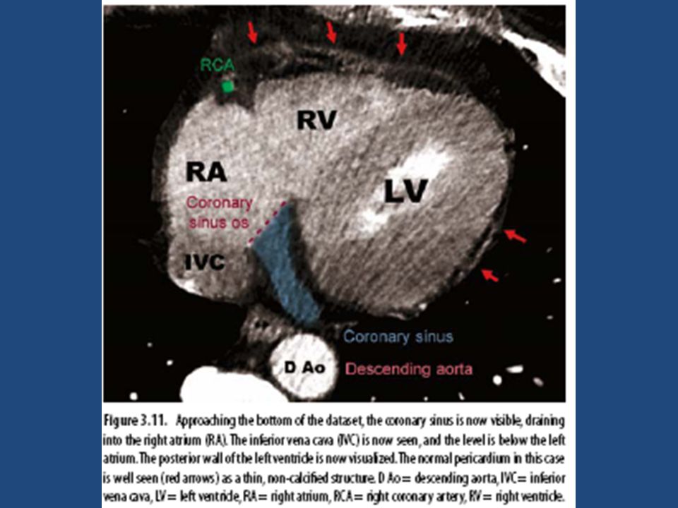
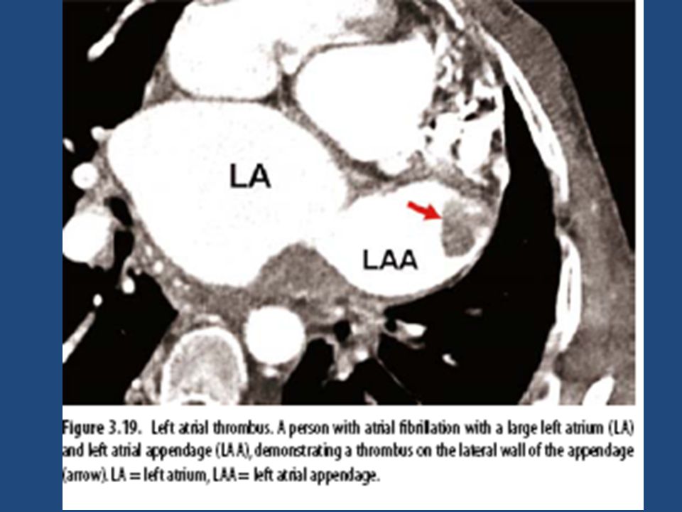
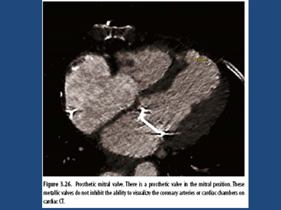
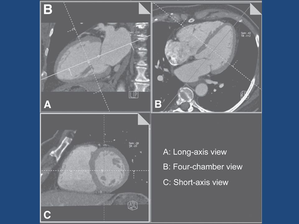
Cardiac Anatomy by CT

47
Performing the Cardiac CT Angiogram 1. one or more planar scout images 2. non-contrast cardiac gated CT 3. a timing scan (can be avoided with certain new scanners) 4. a contrast-enhanced CT angiogram
 4. a contrast-enhanced CT angiogram.")
48
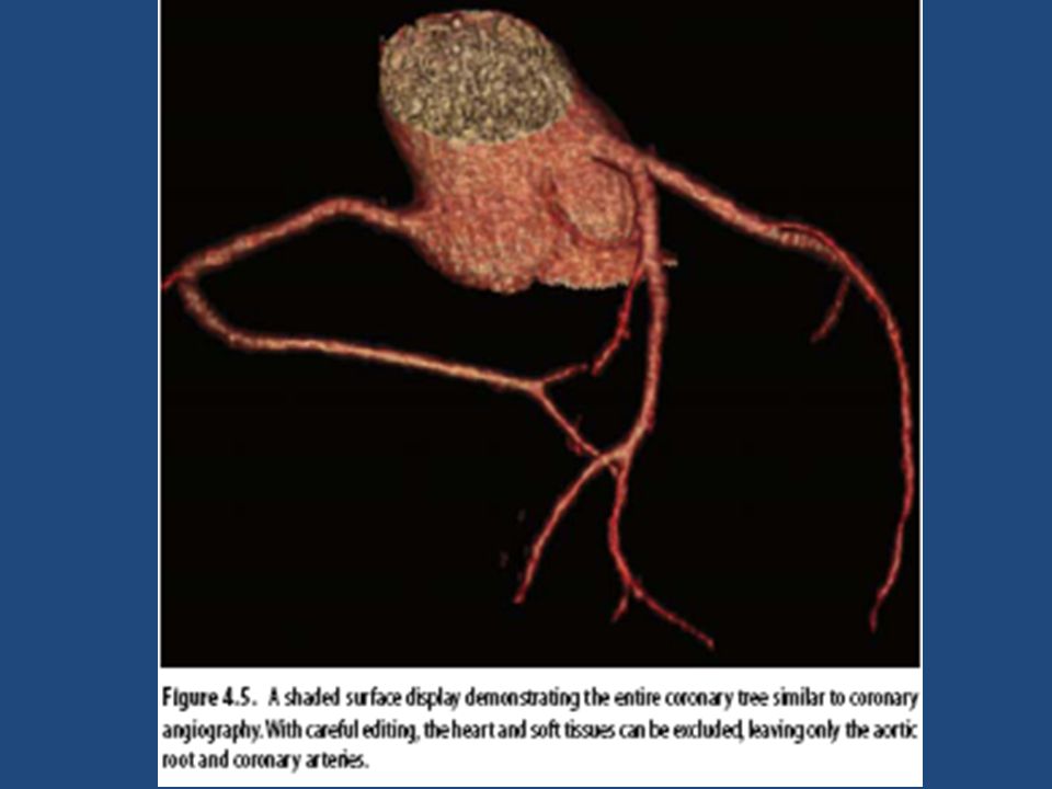
cardiac CT angio- reconstruction Shaded Surface Display Volume Rendering Maximal Intensity Projections Multiplanar Reformatting (MPR)
")
49
Shaded Surface Display Discards all pixels below a certain HU threshold Remaining pixels shaded according to depth and lighting No “upper limit” or threshold Visualize selectively the contrast-enhanced lumens, while automatically deleting vessel wall and connective tissue The picture looks much like a plaster cast of the heart The overestimation of luminal patency in the presence of calcium Partial volume effects

51
Volume Rendering

54
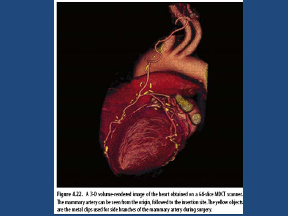
Maximal Intensity Projections only the maximal density values at each point in the 3-D volume are displayed Osseous structures are also removed Relying on density differences and avoiding image smoothing, allows the visualization of smaller vessels and better visualization of LIMA Does not convey depth relationships Doesn’t depict overlapping vessels The lack of 3-D in a single MIP is minimized by displaying multiple MIPs through a single axis Metal and calcium are much brighter than contrast-enhanced lumens Superior accuracy in detecting significant obstructions in the coronary arteries as compared to other techniques

57
Multiplanar Reformatting (MPR) Otherwise known as “curved surface reformation,” multiplanar reformatting Can be used to evaluate the entire coronary tree in one view
 Otherwise known as curved surface reformation, multiplanar reformatting Can be used to evaluate the entire coronary tree in one view")
60
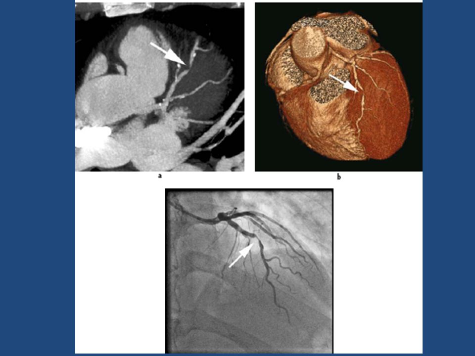
demonstrates a volume-rendered image, which does not well distinguish the calcification from the lumen in the left anterior descending artery (white arrow).
.")
61
demonstrates a maximal intensity projection, displaying the sequential calcifications in the LAD distribution. Since MIP is more transparent, the overlapping vessels (particularly the septal perforators in this image) become more problematic.
 become more problematic..")
62
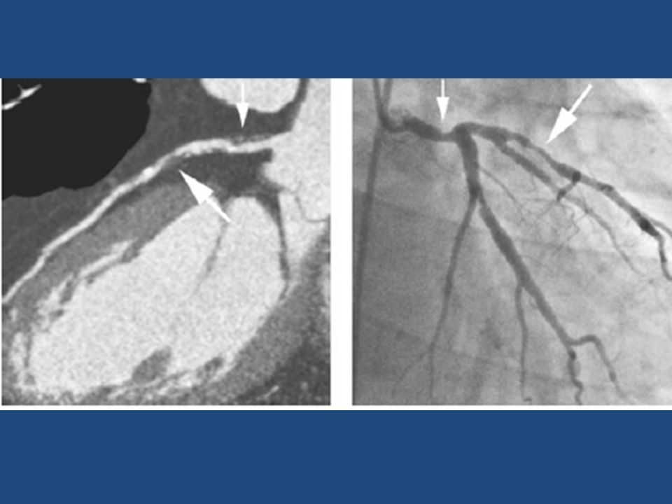
maximal intensity projection of the left anterior descending demonstrating a severe luminal stenosis (non-calcific or “soft”) of the proximal LAD (arrow
 of the proximal LAD (arrow")
64
CTA - Clinical Applications

65
– Does not have the same spatial or temporal resolution as CAG – cannot be performed in all pts (e.g.arrhythmias) – Purely diagnostic -doesn’t provide option for immediate intervention Thus, clinical application of CTA in pts with a high pretest likelihood for CAD is of limited value If the predicted necessity for an intervention is reasonably high, the patient should proceed directly to CAG
 – Purely diagnostic -doesn’t provide option for immediate intervention Thus, clinical application of CTA in pts with a high pretest likelihood for CAD is of limited value If the predicted necessity for an intervention is reasonably high, the patient should proceed directly to CAG")
66
Routine “screening” of asymptomatic individuals by CTA will not be beneficial, since treatment of an asymptomatic stenosis is generally not expected to alter pt’s prognosis

67
Symptomatic with atypical chest pain and have positive or equivocal stress test results, so that invasive coronary angiography is deemed necessary to rule out the unlikely presence of stenoses. Such patients with low or intermediate pretest likelihood are, forexample, younger men and women with atypical chest pain---- CTA

72
CTA -information complementary to CAG Study- In CTO, for intervention, occlusion length & degree of calcification by CT are more accurate predictors of success than CAG CTA may provide information prior intervention of bifurcation lesions or other challenging subsets of coronary stenoses – plaque burden, extent of calcification, 3-D anatomy of vessels

73
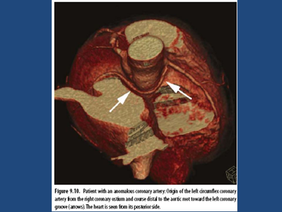
CTA- preferred modality to investigate pts with known or suspected congenital coronary artery anomalies

74
MSCT Coronary Angiography Accuracy Accuracy of testing: – For 64 slice CTA: (for clinically significant occlusions, >50%) Sensitivity: 89 % – (If cardiac cath positive (gold standard), CTA will be positive 89% of the time) Specificity: 96% – (if cath negative, the CTA will not find it 96% of the time.) Negative Predictive Value: 99% – (if negative CTA, cath is negative 99% of time) Positive Predictive Value: 78% – (if positive CTA patient has positive cath 78% of the time) » Clinical Cardiology vol. 30, 9/07

75
Test SensitivitySpecificity CTA 89% (76-99)96% (95-97) Nuc Med Spect 70-80% Stress Echo70-80% ETT60-65%70-75% Cardiac Cath100% Comparison of different Screening tests
96% (95-97) Nuc Med Spect 70-80% Stress Echo70-80% ETT60-65%70-75% Cardiac Cath100% Comparison of different Screening tests")
76
Cardiac Indications – Emergency evaluation of acute chest pain – Cardiac evaluation of a pt with chest pain syn (e.g. anginal equivalent, angina), who is not a candidate for cardiac cath – Management of a symptomatic pt with known CAD (e.g., post-stent, post CABG) when the results of the MDCT may guide the decision for repeat invasive intervention – Assessment of suspected congenital anomalies of coronary circulation
, who is not a candidate for cardiac cath – Management of a symptomatic pt with known CAD (e.g., post-stent, post CABG) when the results of the MDCT may guide the decision for repeat invasive intervention – Assessment of suspected congenital anomalies of coronary circulation.")
77
Assessment of Cardiac Structure & Function Computed Tomography

80
Vertical long axis (Long A) end-diastolic (ED) and end-systolic (ES) images in a patient with normal LVEF, but apical hypokinesis.
 end-diastolic (ED) and end-systolic (ES) images in a patient with normal LVEF, but apical hypokinesis.")
81
Apical aneurysm without thrombus

82
Completed transmural infarction with apical thinning (arrows)
")
83
Assessment of Cardiovascular Calcium

84
CAC Pathognomonic for atherosclerosis Mönckeberg’s calcific medial sclerosis doesn’t occur in coronaries Atherosclerosis is the only vascular disease known to be associated with cor calcification Calcium phosphate (in the hydroxyapatite form) Arterial calcium in athero is a regulated active process similar to bone formation, rather than a passive precipitation of calcium phosphate crystals
 Arterial calcium in athero is a regulated active process similar to bone formation, rather than a passive precipitation of calcium phosphate crystals")
85
Coronary calcium is defined as a lesion above a threshold of 130 HU, with an area of ≥3 adjacent pixels (at least 1mm2)
")
86
Calcium score developed by Agatston - product of the calcified plaque area and max calcium lesion density (1-4 based upon HU) 1–10 - minimal, 11–100 - mild, 101–400 – moderate, >400 - severe Calcium volume score Parameter of choice for serial studies to track progression or regression of atherosclerosis
 1–10 - minimal, 11–100 - mild, 101–400 – moderate, >400 - severe Calcium volume score Parameter of choice for serial studies to track progression or regression of atherosclerosis")
89
Calcium percentile - index of the prematurity of atherosclerosis

90
While the presence of CAC is nearly 100% specific for atherosclerosis, it is not specific for obstr disease since both obstr and non-obstr lesions have calcification present in the intima Comparisons with pathology specimens have shown that the degree of luminal narrowing is weakly correlated with the amount of calcification on a site-by-site basis, whereas the likelihood of signi obstr increases with the total CAC score

91
CAC scanning is not routinely recommended in patients with classical angina symptoms. However, in those with atypical chest pain, a 0 or very low CAC score would render obstructive disease very unlikely

94
Annual event rates and relative risks for cardiac events in 5585 asymptomatic patients at different levels of coronary artery calcium (St Francis Heart Study).The solid line indicates the 2%/year event rate consistent with secondary prevention risk
.The solid line indicates the 2%/year event rate consistent with secondary prevention risk")
95
1. A -ve EBCT test - atherosclerotic plaque, including unstable plaque- unlikely 2. A -ve test - highly unlikely in the presence of signi luminal obstructive dis 3. -ve tests - majority of pts - angiographically normal cor arteries 4. A -ve test - low risk of a cardiovascular event in the next 2 to 5 yrs 5. A +ve EBCT confirms the presence of a cor atherosclerotic plaque

96
6. The greater the calcium, the greater the likelihood of occlusive CAD, but there is not a 1- to-1 relationship, and findings may not be site specific 7. The total amount of calcium correlates best with the total amount of atherosclerotic plaque, although the true “plaque burden” is underestimated 8. A high calcium score may be consistent with moderate to high risk of a cardiovascular event within the next 2 to 5 years

97
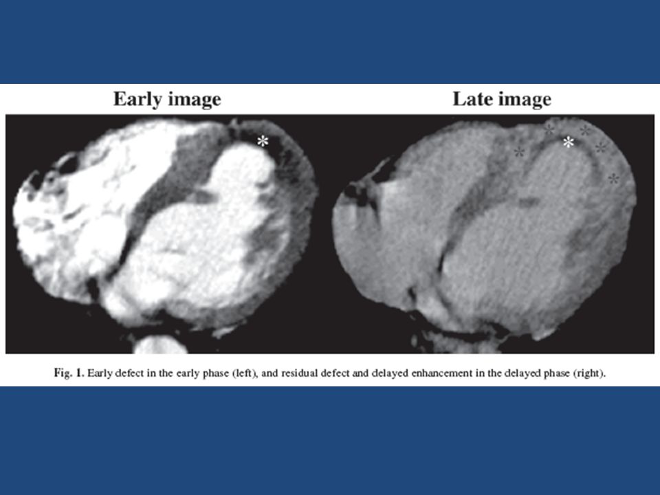
ENHANCEMENT IN AMI (EARLY DEFECT, LATE ENHANCEMENT, RESIDUAL DEFECT) Early defect (ED) is observed as a myocardial perfusion defect (dark zone) in the early image (30–60 s) Residual defect (RD) is observed as smaller dark regions observed in the subendocardium, surrounded by a partially hyperenhanced zone of late enhancement (LE) in the late image (5–10 min) The density of the ED < normal myocardium The LE (112.9 ± 18.5 HU) presented with higher density than RD (59.3 ± 11 HU)
 Early defect (ED) is observed as a myocardial perfusion defect (dark zone) in the early image (30–60 s) Residual defect (RD) is observed as smaller dark regions observed in the subendocardium, surrounded by a partially hyperenhanced zone of late enhancement (LE) in the late image (5–10 min) The density of the ED < normal myocardium The LE (112.9 ± 18.5 HU) presented with higher density than RD (59.3 ± 11 HU)")
99
In AMI patients after successful PCI Depth (subendocardial or transmural) of the ED can predict wall thickness and wall motion in the chronic phase (1 mo).
 of the ED can predict wall thickness and wall motion in the chronic phase (1 mo).")
100
Myocardial enhancement patterns were classified into three groups: Group N (normal), showing no ED, was considered as the normal group; Group SE (region retained in the subendocardium), the region in which ED accounted for less than 50%; and Group TM (region existing transmurally), the region in which ED accounted for more than 50%. Additionally, the mean myocardial wall thickness of the seven regions was calculated and compared in both acute and 1- mo phases.

101
ED VS WALL THICKNESS A case of Group SE is shown in Fig. 3A, and a case in the TM group is shown in Fig. 3B. As shown in Fig. 4A, wall thickness in Group N showed no significant difference between the acute and chronic phases. In Group SE, the wall thickness decreased slightly in the chronic phase (p < 0.05). In Group TM, the wall thickness significantly decreased in the chronic phase (p < 0.001), whose rate of decrease was larger than that of the SE group. As the depth of the ED increased, wall thickness in the chronic phase decreased. ED VS WALL MOTION (RWM SCORE) The RWM in Group N exhibited no difference between the acute and the chronic phases. In Group SE, the RWM improved in the chronic phase, and in Group TM, the RWM did not improve (Fig. 4B). The RWM in Group SE improved, while in Group TM it remained worse. Thus ED by contrast-enhanced CT is useful as a predictor of wall thickness and regional wall motion at 1 mo after successful reperfusion therapy in AMI.
. In Group TM, the wall thickness significantly decreased in the chronic phase (p < 0.001), whose rate of decrease was larger than that of the SE group. As the depth of the ED increased, wall thickness in the chronic phase decreased. ED VS WALL MOTION (RWM SCORE) The RWM in Group N exhibited no difference between the acute and the chronic phases. In Group SE, the RWM improved in the chronic phase, and in Group TM, the RWM did not improve (Fig. 4B). The RWM in Group SE improved, while in Group TM it remained worse. Thus ED by contrast-enhanced CT is useful as a predictor of wall thickness and regional wall motion at 1 mo after successful reperfusion therapy in AMI..")
Similar presentations


>")


 Dynamic scanning implies 15 or more scans in rapid sequence within one.>")


