Download presentation
Presentation is loading. Please wait.

1
Last Topic Collected by JHP

2
Physico-chemical treatment of Hazardous waste

3
Physico-chemical treatment
a range of cool processing techniques aim to reduce the hazardous potential of wastes may also offer re-use or recycling opportunities often used in combination to optimise hazardous wastes treatment Chemical processes use chemical reactions to transform hazardous wastes into less hazardous substances Physical processes enable different waste components to be separated or isolated, for re-use or appropriate treatment or disposal Slide 2 Physico-chemical treatment The term generally covers a range of cool processing techniques which do not include any biological processes. Like other treatment processes, physico-chemical treatment aims to reduce the hazardous potential of the wastes, but physical and chemical processes may also offer opportunities to re-use or recycle parts of the waste, reducing the volume needing disposal. Chemical processes rely on chemical reactions to transform hazardous wastes into less hazardous substances, using the chemical properties of the waste itself to effect the transformation. Physical processes enable different waste components to be separated or isolated, either for re-use or for appropriate further treatment or disposal. An important contribution to lowering the cost of waste treatment comes from the simple practice of keeping hazardous wastes separate from other wastes, and keeping different waste types separate from one another. In this way, opportunities for re-use or recycling are optimised. Further, the complexity of the hazardous waste, and the remaining waste stream,are reduced, which in turn should reduce the amount and complexity of the treatment needed. While each method may be (and often is) used alone, the two processes are often used in combination to optimise hazardous wastes treatment.
 used alone, the two processes are often used in combination to optimise hazardous wastes treatment.")
4
Physico-chemical treatments
On-site vs off-site in central treatment facility Some physical processes on-site eg sedimentation Treatment may be integrated into manufacturing process On-site treatment reduces: volumes needing transport transport costs Slide 3 Physico-chemical treatment facilities Some physical treatment processes may be undertaken on-site by the waste generator. The advantges of on-site treatment include the reduction of waste volumes needing transport to off-site treatment, and the associated savings in costs. On-site treatment is likely to include relatively low cost, high volume treatment processes such as: sedimentation of aqueous wastes neutralisation of acids-alkalis concentration of heavy metals from any metal finishing by precipitation These processes may be integrated into the manufacturing process.

5
Physico-chemical treatment
Off-site treatment allows for dedicated waste handling and treatment systems Should provide: Waste receiving station Storage facilities for wastes awaiting treatment Treatment areas for number and variety of processes used Storage and disposal facilities for treatment residues eg reaction products, filter cake and wastewater Storage for treated wastes to be incinerated, where appropriate Laboratory services Trained personnel Slide 4 Physico-chemcial treatment in a central treatment facility As the previous slide shows, some physical treatment processes may be undertaken by the waste generator on-site, particularly for large volume waste streams such as aqueous wastes. However, the inter-related functions of physico-chemical treatment are typically undertaken at a dedicated facility. Such facilities need to provide the different areas shown on the slide. All of these areas will need to be served by an effective safety management system, and trained personnel will be needed to ensure proper operation. (See also Chapter 5.1 Waste handling and storage and Chapter 5.3 Safe operations and safety management)
")
6
Treatment residues All physico-chemical treatment processes generate residues which may: be hazardous wastes themselves be more concentrated than original waste be suitable for recycling require further treatment need to be landfilled Slide 5 Treatment residues All physico-chemical treatment processes generate residues. These residues are often themselves hazardous waste, and may be more concentrated than the original waste although lower in total volume. If the residue stream is pure, it may be suitable for recycling eg oils from flotation, metals if segregated. Alternatively they may require further treatment, such as solidification eg mixed metal sludges (see also Chapter 6.4 Stabilisation and solidification). Others may require incineration eg distillation residues (see also Chapter 6.5 Thermal treatment). Ultimately there will usually be some residue remaining for landfill disposal eg solidified wastes, incineration residues. Sludge from physico-chemical treatment after pressing Source: Safe hazardous waste management systems 2002 ISWA
. Others may require incineration eg distillation residues (see also Chapter 6.5 Thermal treatment). Ultimately there will usually be some residue remaining for landfill disposal eg solidified wastes, incineration residues. Sludge from physico-chemical treatment after pressing. Source: Safe hazardous waste management systems 2002 ISWA.")
7
Physical processes Many different physical treatment processes
Most are simple and low-cost Choice depends on physical form of waste and its characteristics Options include: ·Separation ·Sedimentation ·Flotation ·Drying ·Evaporation ·Sludge dewatering ·Filtration Slide 6 Physical processes There are a large number of different physical treatment processes, most of which are simple and low-cost. They include the options shown on the slide. Many physical processes rely on gravity, but this basic principle may be adapted in different ways within different processes in an attempt to optimise its effects. Other physical treatment processes use the different properties of materials eg boiling points. particle sizes. The choice of process is dictated by the form of the waste (eg dry powder, liquid) as well as its characteristics. The next 7 slides look at some of the alternative physical treatment options. Filter press Source: Safe hazardous waste management systems 2002 ISWA
 as well as its characteristics. The next 7 slides look at some of the alternative physical treatment options. Filter press. Source: Safe hazardous waste management systems 2002 ISWA.")
8
Examples of separation techniques:
Sieving and screening - for dry materials of different particle size Distillation - to separate liquids Use of washing medium - to extract contaminants from soils or soluble components from solid wastes Slide 7 Separation Simple sieving and screening of wastes can be undertaken with dry materials of different particle size. Distillation can be used to separate liquids, relying on the different boiling points of the different liquids. This is a standard method for solvent recovery. The use of a washing medium may also be used, for example to extract contaminants from soils, or to wash soluble components from solid wastes, such as aggregates or gravel.

9
Adsorption Slide 8 Adsorption
Adsorption is used to remove hazardous components from liquid or gaseous hazardous wastes, and is commonly used to remove trace organic constituents from wastewater. The slide shows some common types of adsorbents and their application. Granular activated carbon is the most commonly used adsorbent material, but may be expensive. Adsorption is especially useful in the final stages of waste treatment, and is often used in combination with other treatment methods.

10
Sedimentation Used to separate particles held in suspension in a liquid which is principally aqueous Uses gravity May require mechanical or manual stirring Suitable for a wide range of hazardous wastes metals in waste water neutralised acids and alkalis containing suspended metal hydroxides metals that have been precipitated Sludges may need further screening, drying or dewatering Separated liquid may need further treatment Slide 9 Sedimentation Sedimentation uses gravitational forces to settle the denser components in an aqueous liquid. For hazardous wastes, there is a wide possible range of waste types which may be treated in this way, including those shown on the slide. Simple sedimentation tanks are static cylinders with a conical base from which collection and thickening of sludge is facilitated. Depending on the gradient of the base cone, mechanical or manual stirring may be necessary to collect the sludges. Sludges once collected are either pumped or moved (eg by mechanical buckets) for further screening, or to drying or dewatering facilities while the separated liquid may need further treatment before disposal. Discussion: Trainers could ask students to consider which additional waste types might be amenable to this kind of treatment.
 for further screening, or to drying or dewatering facilities while the separated liquid may need further treatment before disposal. Discussion: Trainers could ask students to consider which additional waste types might be amenable to this kind of treatment.")
11
Sedimentation - example
Slide 10 Sedimentation - example The slide shows an example of sedimentation (also sometimes called clarification). The vessel contents shown are somewhat unusual as normally a relatively clear liquor would result from hazardous waste treatment applications, but in this example a scum is visible as it follows a bioreactor stage, and (as a result of poor up-stream design) there is some biomass carry-over. The motors drive a "rake" consisting of shallow blades fitting the conical section at the bottom of the vessel which turns slowly and facilitates periodic de-sludging via the bottom outlet. The rake is designed and operated in such a way as to disturb the other contents as little as possible. Source: Davd S Newby 1991
. The vessel contents shown are somewhat unusual as normally a relatively clear liquor would result from hazardous waste treatment applications, but in this example a scum is visible as it follows a bioreactor stage, and (as a result of poor up-stream design) there is some biomass carry-over. The motors drive a rake consisting of shallow blades fitting the conical section at the bottom of the vessel which turns slowly and facilitates periodic de-sludging via the bottom outlet. The rake is designed and operated in such a way as to disturb the other contents as little as possible. Source: Davd S Newby")
12
Flotation Relies on the natural behaviour of particles less dense than water Is suitable for a range of waste types eg oil/water separation Efficiency can be improved by blowing air through the liquid size of air bubbles should be varied according to waste type Slide 11 Flotation Flotation relies on the natural floating effects of particles which are less dense than water. The efficiency of flotation can be improved by blowing air through the liquid. The bubbles attach to the light particles and gather together to make a foam on the surface. The size of the air bubbles can be varied according to the waste type, with small bubbles being more efficient but requiring more precise equipment which in turn requires more maintenance. If the bubbles of air are too big they have the opposite effect from that desired ie they encourage mixing rather than separation of the different materials. Flotation is the standard way of separating oil and water mixtures. Discussion: Trainers could ask students to consider which waste types might be amenable to this kind of treatment.

13
Drying and evaporation
May be needed after sedimentation Options include: Sludge drying beds Centrifugal separation Filtering and pressing Slide 12 Drying and evaporation After sedimentation, sludges still contain high percentages of water and may need to be further dried before disposal, depending on the regulations concerning the disposal route eg land spreading. There are a number of ways for the sludge to be dried: Sludge drying beds This simple, low cost method is only suitable in certain climates, for some wastes and for small quantities. Sludges are poured onto sand from where the water will either evaporate off or will percolate into the sand. It is important to be sure that this process does not result in undesirable matter in the sludge being returned to the environment. Centrifugal separation This method uses centrifugal force to accelerate the separation of sludge into particles and liquid, resulting in clear liquid and a sludge cake. Sludges containing sand cannot be treated in this way, because of the abrasive nature of the sand. Sludges containing long fibres or bulky items are also not suitable. Because the operation of the centrifuge requires a power supply, this may not always be a suitable option. Filtering and pressing Filtering of wastes is probably the most common physical treatment method. It is suitable for a variety of different wastes and there are a wide range of different filters and filter presses which can be used. (See next slide) These include membranes, bar screens, filter presses and belt filters. Filter processes are often an integral part of the primary production process, to reduce the quantity of waste generated. Membranes are used for simple filtration, with the size of the mesh screen dictating the efficiency of the process. Membranes are also used for reverse osmosis, for example for oily wastes and leachates.
 These include membranes, bar screens, filter presses and belt filters. Filter processes are often an integral part of the primary production process, to reduce the quantity of waste generated. Membranes are used for simple filtration, with the size of the mesh screen dictating the efficiency of the process. Membranes are also used for reverse osmosis, for example for oily wastes and leachates.")
14
Drying and evaporation - example
Slide 13 Drying and evaporation - example Filter presses consist of flat plates covered with fabric, with drainage channels to collect the liquid which is pressed out of the sludge material. This is a batch-fed process where the residence time of the sludge is around 30 minutes. Belt or band filters are commonly used in sludge dewatering processes in many countries, and comprise two porous belts which pass over a series of rollers and squeeze the sludge material between them, using progressive amounts of pressure to remove the water. Unlike filter presses, this is a continuous process. (See slide) Filters are at risk of corrosion because of the humid atmosphere in which they operate. Materials used for their manufacture must therefore be of high quality, and regular maintenance must be undertaken. am management, Wiley Belt filter - a continuous filtering process widely used for dewatering sludges
 Filters are at risk of corrosion because of the humid atmosphere in which they operate. Materials used for their manufacture must therefore be of high quality, and regular maintenance must be undertaken. am management, Wiley. Belt filter - a continuous filtering process widely used for dewatering sludges.")
15
Chemical processes change chemical properties of waste
use a chemical to treat a chemical need details of waste composition and reactivity need qualified staff to: assess waste composition monitor chemical reaction check reaction results Options include: ·Reduction and oxidation ·Neutralisation ·Precipitation Slide 14 Chemical processes Chemical treatment processes typically cause a permanent change in the chemical properties of a hazardous waste so as to reduce or eliminate toxicity. Before chemical treatment methods - which involve the use of a chemical to treat a chemical - it is important to know as accurately as possible the composition of the waste and the way it will react. Its reaction will be affected and possibly inhibited by trace components in the waste. Qualified staff are needed to assess the waste composition, follow the progress of the chemical reaction and to check the quality of the reaction results. There are a number of chemical treatment processes in common use, including: Reduction and oxidation Neutralisation Precipitation These are addressed on the next five slides.

16
Reduction and oxidation
Some common oxidising and reducing reagents Oxidising reagents Sodium or calcium hypochlorite Hydrogen peroxide Chlorine Potassium permanganate UV Ozone Reducing reagents Ferrous sulphate Sodium sulphite Sulphuric acid Iron Aluminium Zinc Sodium borohydride Slide 15 Reduction and oxidation This process is used to reduce or destroy the toxicity of waste by changing its state of oxidation. Solutions containing hexavalent chromium, cyanides, sulphides and many organic wastes such as pesticides and phenols are treated by reduction or oxidation. The origins of many wastes treated in this way are from electroplating, metals manufacturing and ore extraction. The slide shows some common oxidising and reducing reagents. While many chemicals are theoretically easy to use for reduction and oxidation, in practice they are less easy. There are also many risks with certain chemicals. The easiest oxidation reagents to use are sodium or calcium hypochlorite, and these are also often the cheapest. As a reducing reagent, ferrous sulphate is the cheapest and easiest to use. Sodium sulphite also requires the use of sulphuric acid.

17
Oxidation in practice Enables avoidance of harmful side reactions
Needs expert design, careful operation to be safe Is cost effective Enables avoidance of harmful side reactions Commonly used for cyanides Easiest oxidising reagents: sodium or calcium hypochlorite Slide 16 Oxidation in practice Oxidation processes require expert design in order for them to be safe and cost effective. The commonest wastes which are dealt with by oxidation are cyanides from electroplating or case-hardening steel. To treat these, the easiest and often the cheapest oxidising reagents are sodium or calcium hypochlorite. Other wastes suitable for being treated by oxidation include organic compounds in dilute wastewater eg phenols, mercaptons, benzidines and unsaturated acids. Oxidation avoids hamful side reactions eg the formation of chlorophenols.

18
Reduction in practice Commonly used for chromates and chromic acids from chromium plating and tanning industries Cr VI reduced to Cr III then removed by precipitation Common reducing reagents: ferrous sulphate sodium sulphite/sulphuric acid Slide 17 Reduction in practice The most common wastes which are treated by reduction are the chromates and chromic acids from chromium plating and tanning industries. The hexavalent ion (Cr VI) which is present in chromic acid is the most toxic and this is reduced to Cr III which can then be removed using alkaline precipitation. The most commonly used reducing reagent is ferrous sulphate which is obtained from used acids from pickling baths. A combination of sodium sulphite and sulphuric acid is also commonly used.
 which is present in chromic acid is the most toxic and this is reduced to Cr III which can then be removed using alkaline precipitation. The most commonly used reducing reagent is ferrous sulphate which is obtained from used acids from pickling baths. A combination of sodium sulphite and sulphuric acid is also commonly used.")
19
Chemical Oxidation and reduction:
Oxidation reduction methods provide another important chemical treatment alternative for hazardous wastes. One important chemical redox treatment involves the oxidation of cyanide wastes from metal finishing industry, using chlorine in alkali solution. In this reaction CN- is first converted to a less toxic cyanate. Further chlorination oxidises the cyanate to simple carbondioxide and nitrogen gas. important redox treatment process is the reduction of hexavalent chromium Cr(VI) to trivalent chromium Cr(III) in large electroplating operations. Sulphur dioxide is used as the reducing agent and the reactions are as follows.
 to trivalent chromium Cr(III) in large electroplating operations. Sulphur dioxide is used as the reducing agent and the reactions are as follows.")
20
A large variety of oxidisable contaminants in waste water and sludges are oxidised by ozone which can be generated on site by an electrical discharge through dry air or oxygen.

21
Ozonolysis: Ozone is a very powerful oxidising agent. Although this process has not been demonstrated in any full-scale facility, its application to TCDD and PCBs is quite promising. With respect to TCDD it was demonstrated that if the dioxins were suspended as an aerosol combined with CCl4, 97% degradation of TCDD was possible. Ozone in conjunction with UV radiation has been shown effective for the destruction of polychlorinated phenols and pesticides. In both the cases the key requirements were to concentrate the TCDD in a medium where they were susceptible to attack and provide a free radical for reaction with dioxin molecule.

22
Neutralisation Used for wide variety of acidic and alkaline wastes
A batch process Used for wide variety of acidic and alkaline wastes Acid wastes are neutralised by alkalis, and vice versa Used to treat liquid wastes, sludges and gases Reactions must be laboratory tested to control pH, identify complementary reagents Neutralised liquid usually sent for sedimentation Slide 18 Neutralisation Neutralisation is a common industrial treatment process for a wide variety of acidic and alkaline wastes. Neutralisation is most often used to treat liquid wastes, but sludges and gases are also treated. When they are outside the pH range 4.3 – 8.3, acid wastes are neutralised by alkalis, and vice versa. Self-neutralisation is often used, where a waste acid and waste alkali neutralise each other. Otherwise, lime or sodium hydroxide are the most widely used neutralising agents for acids. Sulphuric and hydrochloric acid are the most commonly used neutralising agents for alkalis. Each neutralisation process must be previously tested in a laboratory to avoid reactions which may be too slow, too rapid or have undesired gas emissions. Neutralisation is a batch process, usually at a rate of 10m3 at a time. The variability of the waste does not permit a continuous process. The pH of the mixture must be continuously monitored, and the neutralised liquid is usually sent for sedimentation.

23
Precipitation Causes soluble substances to become less soluble/insoluble Often used in combination with other treatment processes eg reduction, neutralisation Effective treatment for wastewater containing toxic metals which arise in metal-plating and finishing industry, and mining Calcium hydroxide (lime) most widely used reagent Slide 19 Precipitation Chemical precipitation causes soluble substances to become less soluble or insoluble. The treatment is effective in treating wastewater containing toxic metals such as arsenic, barium, cadmium, chromium, copper, lead, mercury, nickel and zinc. These metal-containing wastewaters arise for example in the metal-plating and finishing industry and in mining. Precipitation using calcium hydroxide is the most widely used method, but carbon, sulphide and sodium borohydride are also used. Precipitation is often used in combination with other treatment processes. For example, after reducing CrVI to Cr III, the CrIII is often precipitated. Similarly, after neutralisation, metals may be precipitated. Precipitation may itself be followed by sedimentation or solidification (see Chapter 6.4 Stabilisation and solidification).
 most widely used reagent. Slide 19 Precipitation. Chemical precipitation causes soluble substances to become less soluble or insoluble. The treatment is effective in treating wastewater containing toxic metals such as arsenic, barium, cadmium, chromium, copper, lead, mercury, nickel and zinc. These metal-containing wastewaters arise for example in the metal-plating and finishing industry and in mining. Precipitation using calcium hydroxide is the most widely used method, but carbon, sulphide and sodium borohydride are also used. Precipitation is often used in combination with other treatment processes. For example, after reducing CrVI to Cr III, the CrIII is often precipitated. Similarly, after neutralisation, metals may be precipitated. Precipitation may itself be followed by sedimentation or solidification (see Chapter 6.4 Stabilisation and solidification).")
24
Chemical precipitation:
This technique can be applied to almost any liquid waste stream containing a precipitable hazardous constituent. By properly adjusting pH, the solubility of toxic metals can be decreased, leading to the formation of a precipitate that can be removed by settling and filtration. Quite often lime [Ca(OH)2] or caustic soda is used for precipitation of the metal ions as metal hydroxides. For example the following reaction suggests the use of lime to precipitate the metal as hydroxide.
2] or caustic soda is used for precipitation of the metal ions as metal hydroxides. For example the following reaction suggests the use of lime to precipitate the metal as hydroxide.")
25
Chemical ppt method Chromium is precipitated as hydroxide.
Sodium carbonate also has been used to precipitate metals as hydroxides (Fe(OH)3•XH2O), carbonates (CdCO3), basic carbonate salts (2PbCO3•Pb(OH)2). Carbonate ion hydrolyses in water to give hydroxide ion
3•XH2O), carbonates (CdCO3), basic carbonate salts (2PbCO3•Pb(OH)2). Carbonate ion hydrolyses in water to give hydroxide ion.")
26
Chemical ppt methods Even lower concentrations of metals in the effluent can be removed by precipitating them as sulphides. Ferrous sulphide can be used as a safe source of sulphide ion to produce sulphide precipitates with other metals that are less soluble than ferrous sulphide. Reducing agents such as sodium borohydride can be used to precipitate the metal ions from solution in the elemental form.

27
Chemical Methods Neutralisation
Waste acid with an alkali e.g. sulfuric acid with sodium carbonate: H2SO4 + CO3 2- → SO CO2 + H2O Oxidation Using common oxidising substances such as hydrogen peroxide or calcium hypochlorite e.g. cyanide waste with calcium hypochlorite: CN- + OCl- → OCN- + Cl- OCN- + H3O+ → CO2 + NH3 Reduction Used to convert inorganic substances to a less mobile and toxic form e.g. reducing Cr(VI) to Cr(III) by the use of ferrous sulphate: 14H+ + Cr2O Fe2+ → 6Fe3+ + 2Cr3+ + 7H2O Hydrolysis Decomposition of hazardous organic substances e.g. decomposing certain organophosphorus pesticides with sodium hydroxide. Precipitation Particularly useful for converting hazardous heavy metals to a less mobile, insoluble form prior to disposal to a landfill e.g. precipitation of cadmium as its hydroxide by the use of sodium hydroxide: Cd2+(aq) + 2OH- → Cd(OH)2(s)
 to. Cr(III) by the use of ferrous sulphate: 14H+ + Cr2O Fe2+ → 6Fe3+ + 2Cr3+ + 7H2O. Hydrolysis. Decomposition of hazardous organic substances e.g. decomposing certain organophosphorus. pesticides with sodium hydroxide. Precipitation. Particularly useful for converting hazardous heavy metals to a less mobile, insoluble form. prior to disposal to a landfill e.g. precipitation of cadmium as its hydroxide by the use of. sodium hydroxide: Cd2+(aq) + 2OH- → Cd(OH)2(s)")
28
Hydrolysis: Hydrolysis treatment can be given to those hazardous waste constituents which are very reactive with water. Examples of those substances are halides, carbide, hydride, alkoxide, and active metal.

29
Ion exchange: Ion exchange is judged to have some potential for the application of interest in situations where it is necessary to remove dissolved inorganic species. However other competing processes - precipitation, flocculation and sedimentation - are broadly applicable to mixed waste streams containing suspended solids and a spectrum of organic and inorganic species. These competing processes also usually are more economical. The use of ion exchange is therefore limited to situations where polishing step was required to remove an inorganic constituent that could not be reduced to satisfactory levels by preceding treatment processes. One example for this is the use of anion exchanges for the removal of anionic nickel cyanide complex and chromate ions from waste solutions. Ion -exchange resins have also been used in the removal of radionuclides from radioactive wastes

30
Wet air oxidation: It is the aqueous phase oxidation of dissolved or suspended organic substances at elevated temperatures ( oC) and pressures (2000 kPa to 20,000 kPa) water. Which makes up the bulk of the aqueous phase, serves to catalyse the oxidation reactions so they proceed at relatively low temperature, and at the same time serves to moderate the oxidation rates removing excess heat by evaporation. It also acts as excellent heat transfer medium, which enables the wet air oxidation process to be thermally self-sustaining with relatively low organic feed concentrations. The high pressures allow high concentration of oxygen to be dissolved in water and the high temperature assist the reaction to occur. In wet air oxidation, the waste is pumped into the system with high-pressure pump and mixed with air from an air compressor. The waste is passed through a heat exchanger and then to a reactor where atmospheric oxygen reacts with the organic matter waste, sometimes in the presence of catalysts. The oxidation is accomplished by a temperature increase. The gas and liquid phases are separated. System pressure is controlled to maintain the reaction temperature. The process can be used for the removal of cyanide from electroplating waste solutions.
 and pressures (2000 kPa to 20,000 kPa) water. Which makes up the bulk of the aqueous phase, serves to catalyse the oxidation reactions so they proceed at relatively low temperature, and at the same time serves to moderate the oxidation rates removing excess heat by evaporation. It also acts as excellent heat transfer medium, which enables the wet air oxidation process to be thermally self-sustaining with relatively low organic feed concentrations. The high pressures allow high concentration of oxygen to be dissolved in water and the high temperature assist the reaction to occur. In wet air oxidation, the waste is pumped into the system with high-pressure pump and mixed with air from an air compressor. The waste is passed through a heat exchanger and then to a reactor where atmospheric oxygen reacts with the organic matter waste, sometimes in the presence of catalysts. The oxidation is accomplished by a temperature increase. The gas and liquid phases are separated. System pressure is controlled to maintain the reaction temperature. The process can be used for the removal of cyanide from electroplating waste solutions.")
31
Other chemical processes
Practical options can include: Hydrolysis eg for some pesticides Electrolysis eg for silver recovery from photographic wastewaters Dechlorination eg for solvents Chlorolysis eg for residues from chlorinated hydrocarbon manufacture Slide 20 Other chemical processes Many other chemical processes can theoretically be used to treat hazardous wastes. Some of the more practical include: Hydrolysis Certain hazardous wastes including some pesticides react with water. Hydrolysis causes substances to break down in water and can either be carried out in acid or alkaline conditions. This process should be carried out in very carefully controlled conditions. Electrolysis In electrolysis, an electric current is passed through an electrolyte (a solution that contains ions and conducts electricity).This method is used to recover silver from photographic wastewaters. It is also used to treat heat treatment salts containing a high percentage of cyanide. Dechlorination Dechlorination is a process where chlorine is chemically removed from chlorinated organic compounds by using powerful reducing reagents. A number of persistent organic pollutants (POPs) now controlled under the so-called POPs Convention, are chloro-organic materials including long-banned pesticides such as DDT, Dieldrin and Aldrin, and polychlorinated biphenyls (PCBs) which were previously used in electrical transformers and capacitors. Other heavily chlorinated wastes include many solvents used, inter alia, for industrial cleaning eg perchloroethylene (tetrachloroethene) or carbon tetrachloride (tetrachloromethane). However, in practice, dechlorination is not regarded as an attractive option because of the very high cost of reagents as well as operational difficulties in their handling and storage. Incineration is still the preferred treatment option, in which case recovery of the chlorine content as hydrochloric acid is an option. Chlorolysis Chlorolysis (ie exhaustive chlorination) of resides from chlorinated hydrocarbon manufacture has been developed on a commercial scale as an in-house reclamation method. It converts the residues largely to carbon tetrachloride which is a commercial product.
.This method is used to recover silver from photographic wastewaters. It is also used to treat heat treatment salts containing a high percentage of cyanide. Dechlorination. Dechlorination is a process where chlorine is chemically removed from chlorinated organic compounds by using powerful reducing reagents. A number of persistent organic pollutants (POPs) now controlled under the so-called POPs Convention, are chloro-organic materials including long-banned pesticides such as DDT, Dieldrin and Aldrin, and polychlorinated biphenyls (PCBs) which were previously used in electrical transformers and capacitors. Other heavily chlorinated wastes include many solvents used, inter alia, for industrial cleaning eg perchloroethylene (tetrachloroethene) or carbon tetrachloride (tetrachloromethane). However, in practice, dechlorination is not regarded as an attractive option because of the very high cost of reagents as well as operational difficulties in their handling and storage. Incineration is still the preferred treatment option, in which case recovery of the chlorine content as hydrochloric acid is an option. Chlorolysis. Chlorolysis (ie exhaustive chlorination) of resides from chlorinated hydrocarbon manufacture has been developed on a commercial scale as an in-house reclamation method. It converts the residues largely to carbon tetrachloride which is a commercial product.")
33
Hazardous waste compatibility
Slide 7 Hazardous waste compatibility 2 The slide shows the chemical compatibility of some waste types.

34
Combined physical & chemical processes
Two common examples: ·Solvent extraction ·Coagulation and flocculation Slide 21 Combined physical and chemical processes As has been stated, physical and chemical processes are often used in combination. Two common examples where this takes place are: Solvent extraction Coagulation and flocculation Solvent extraction can be used to remove selected organic contaminants from wastewaters. During the extraction process, aqueous waste containing dissolved or suspended organic material is mixed with an immiscible solvent which dissolves the organic material. This is followed by a separation stage. Coagulation is a common method to treat oil/water emulsions such as cutting oils and other water- soluble oils. It involves the aggregation of fine particles from a solution by the addition of coagulants together with high intensity mixing. This is followed by flocculation where the aggregation of coagulated particles combine to form large visible floc particles. Flocculation is improved by gentle stirring. The effectiveness of coagulation and flocculation can be increased by the addition of a physical treatment step, such as sedimentation. (See slide) Coagulation and flocculation
 Coagulation and flocculation.")
35
Physico-chemical treatment
Slide 22 Physico-chemical treatment The slide shows the typical processes undertaken at a central treatment facility. Discussion: Trainers are encouraged to work through the different stages, perhaps using different waste types eg acids, organics, oils, as examples. Source: David S Newby

36
Thermal treatment

37
Thermal treatment methods include:
Thermal treatment = destruction of hazardous waste by thermal decomposition Thermal treatment methods include: incineration - complete combustion using excess oxygen gasification - incomplete combustion in the partial absence of oxygen pyrolysis - thermal decomposition in the total absence of oxygen Slide 2 Definitions The term thermal waste treatment is used for all processes in which hazardous wastes are destroyed by thermal decomposition. This may involve the total or partial combustion of the waste. Combustion is an oxidation process, generally using oxygen from the air. Combustion temperatures vary depending on the process; for instance the temperature normally reached in a rotary kiln is around 1100oC. There is a distinction between combustion with a lack of oxygen (ie incomplete combustion) and complete combustion. Because of the heterogeneous nature of waste, complete combustion requires an excess of air in order to avoid unburned materials, particularly carbon monoxide. During the thermal process, the carbon and hydrogen constituents in the waste are transformed into carbon dioxide and water. After combustion, on average 20-35% of the waste (by weight) remains, although the volume reduction can reach 90%, depending on the waste composition and the type/efficiency of the combustion process. Some wastes may require the addition of fuel to achieve complete combustion.
 and complete combustion. Because of the heterogeneous nature of waste, complete combustion requires an excess of air in order to avoid unburned materials, particularly carbon monoxide. During the thermal process, the carbon and hydrogen constituents in the waste are transformed into carbon dioxide and water. After combustion, on average 20-35% of the waste (by weight) remains, although the volume reduction can reach 90%, depending on the waste composition and the type/efficiency of the combustion process. Some wastes may require the addition of fuel to achieve complete combustion.")
38
Application of thermal treatment
Suitable for organic wastes Thermal treatment processes: require high capital investment are highly regulated need skilled personnel require high operating and safety standards have medium to high operating costs Slide 3 Application of thermal treatment Thermal treatment is suitable for wastes with a high carbon and hydrogen content ie organic wastes. Around 20% of industrial waste and 30% of domestic waste is typically incombustible. This includes ferrous and non-ferrous metals such as iron and aluminium. In some cases the first stage of the combustion process is an evaporation stage, where the water is first removed for treatment, prior to the actual combustion. Application of thermal processing of hazardous wastes is constrained by the costs, the need for skilled personnel and the requirements for high operating and safety standards. Safety precautions include a requirement for automatic shutdown of the plant when specified, vital parameters (such as required temperature) are not complied with. For thermal treatment to be an acceptable and environmentally sound waste treatment process, properly designed, operated and controlled, the most important factors are good combustion control and effective flue gas cleaning. These in turn require high capital investment, comprehensive regulation, trained personnel and high operating standards. The complexity of the technology and its need for skilled operation and management result in moderate to high operating costs.
 are not complied with. For thermal treatment to be an acceptable and environmentally sound waste treatment process, properly designed, operated and controlled, the most important factors are good combustion control and effective flue gas cleaning. These in turn require high capital investment, comprehensive regulation, trained personnel and high operating standards. The complexity of the technology and its need for skilled operation and management result in moderate to high operating costs.")
39
Good practice in hazardous waste combustion
3 Ts: Time Temperature Turbulence Flue gas cleaning systems Slide 4 Good practice in hazardous waste combustion Waste combustion is a well-established and proven process. Experience has shown that the key factors are to maximise combustion efficiency and minimise the formation and dispersal of harmful emissions. The so-called ‘3 Ts’ which influence these factors are: the residence time of the waste in the combustion zone, usually recommended as a minimum of 2 seconds the temperature - at least 850oC the turbulence - movement of air in the burner Plus the addition of sufficient excess air. To manage emissions, there are several different flue gas cleaning stages, using filters, adsorbents and gas scrubbers. For hazardous waste incineration, which is the most widely used thermal treatment process, a large number of recent technology developments enable good combustion control. These technological improvements are coupled with strict environmental and regulatory controls in many countries.

40
Examples of Calorific Value
Mixed waste from plant cleaning operations 10, ,000 kj/kg Wastewater ,000 kj/kg (0 - 10,000kj/kg depending on organic content) Industrial sludge , ,000 kj/kg Paints and varnishes >20,000 kj/kg Chlorinated hydrocarbons 5, ,000 kj/kg For comparison, MSW = ~10,000kj/kg Slide 6 Examples of Calorific Value The slide shows some examples of hazardous wastes and their CV. As can be seen, the CV of industrial waste varies considerably, because of the huge variety of different industrial wastes. Source: Indaver
 Industrial sludge 1, ,000 kj/kg. Paints and varnishes >20,000 kj/kg. Chlorinated hydrocarbons 5, ,000 kj/kg. For comparison, MSW = ~10,000kj/kg. Slide 6 Examples of Calorific Value. The slide shows some examples of hazardous wastes and their CV. As can be seen, the CV of industrial waste varies considerably, because of the huge variety of different industrial wastes. Source: Indaver.")
41
Combustion Requires: addition of excess air mechanical mixing of waste
even distribution and aeration of waste Behaviour of waste during combustion varies according to its heat value and its form Some low CV wastes burn easily = straw Some low CV wastes are difficult to burn = wet sludges Some high CV wastes burn easily = tank bottoms Some high CV wastes are difficult to burn = contaminated soils, certain plastics Certain wastes change their physical characteristics during combustion Slide 7 Combustion As has been shown on slide 4, complete combustion requires the addition of excess air to ensure sufficient air throughout the combustion process, as well as turbulence, a suitable residence time and the correct temperature. Mechanical mixing of the waste is also necessary, and during combustion this may be achieved for example by the movements of the incinerator grate. Mixing of wastes before they are fed into the furnace can also help to ensure even distribution and aeration. The behaviour of waste during combustion varies according to its heat value and its form. The slide shows some examples of this. Certain wastes change their physical characteristics during combustion eg some solids become liquids. The igniting of gases and liquids given off by the waste as it combusts can cause problems for plant operators in regulating the process, and can also damage equipment.

42
Combustion techniques
Bed plate furnaces: use gravity to mix waste - used for homogeneous and wet wastes such as sludge cake Fluidised bed furnaces: waste is introduced into a bed of sand which is kept in suspension - used for wastes of similar size and density Incineration grates: wastes fed onto the grate are turned or moved to ensure aeration of the waste mass via holes in the grate - used for solid wastes eg municipal wastes, not liquids or sludges Rotary kilns: wastes are placed in slowly rotating furnace - suitable for solids, sludges and liquids Slide 8 Combustion techniques There are a number of technologies which are designed and adapted to combust different waste types and to ensure the homogeneous mixing necessary for complete combustion. Bed plate furnaces: uses the forces of gravity to help in the mixing of the waste, as the waste is moved between a series of metal plates. Waste is scraped from one plate from where it falls onto the next, which has a higher temperature. This method is used for homogeneous and wet wastes such as sludge cake, and ‘pasty’ wastes. Fluidised bed furnaces: waste is introduced into a bed of sand which is kept in suspension by an ascending current of air. The bed is heated to several hundred degrees and provides sufficient inertia for steady combustion. This method is suitable for wastes of similar size and density, and for wastes which have been pre-treated to reduce them in size. The addition of suitable material eg lime can enable flue gas desulphurisation to be achieved within the process. Incineration grates: wastes fed onto the grate are turned or moved to ensure aeration of the waste mass via holes in the grate. This method is suitable for solid wastes eg municipal wastes which do not comprise liquids, pastes or sludges that would run through the grate. Rotary furnaces: wastes are placed in a refractory-lined furnace which rotates on itself at a variable speed. (The refractory brick lining is specially treated to withstand high temperatures as well as extreme temperature changes and the action of molten materials and hot gases.) This method is suitable for all kinds of hazardous waste (liquids, solids, sludges and packed waste). Normally a rotary furnace is much larger than an incineration grate to handle the same capacity of waste.
 This method is suitable for all kinds of hazardous waste (liquids, solids, sludges and packed waste). Normally a rotary furnace is much larger than an incineration grate to handle the same capacity of waste.")
43
Operation of the furnace
Must be consistent Needs: good understanding of waste characteristics technical skills control of waste feed mixing of wastes temperature to be kept at required level despite variations in waste excess air flue gas control regular maintenance Slide 9 Operation of the furnace As has been shown (see slide 4) complete combustion requires certain parameters to be maintained consistently. In order to maintain that consistent process, it is necessary for the operator to: Keep the temperature at the required level despite variations in the waste. The temperature varies according to the waste, and can be between 850oC and 1200oC. Regulation of the waste feed to maintain the required temperature may require mixing of low and high CV wastes, which needs good understanding of the waste and its characteristics as well as technical skill Maintain adequate excess air Control the quality of the flue gases Regular maintenance is also very important because most elements of the furnace operate in difficult conditions. Regular maintenance should also be undertaken for all other mechanical parts such as refractory lining, pumps, fuel feed and extraction systems, as well as the monitoring and control apparatus. Source: David C Wilson
 complete combustion requires certain parameters to be maintained consistently. In order to maintain that consistent process, it is necessary for the operator to: Keep the temperature at the required level despite variations in the waste. The temperature varies according to the waste, and can be between 850oC and 1200oC. Regulation of the waste feed to maintain the required temperature may require mixing of low and high CV wastes, which needs good understanding of the waste and its characteristics as well as technical skill. Maintain adequate excess air. Control the quality of the flue gases. Regular maintenance is also very important because most elements of the furnace operate in difficult conditions. Regular maintenance should also be undertaken for all other mechanical parts such as refractory lining, pumps, fuel feed and extraction systems, as well as the monitoring and control apparatus. Source: David C Wilson.")
44
Energy recovery Waste combustion produces heat
but combustion of low CV wastes may not be self-supporting Energy recovery is via production of steam to generate electricity Only steam production: 80% efficiency is typical Steam can be used for in-house demands Steam can be delivered to adjacent users eg other industrial plants Electricity can be generated: 25% efficiency typical Opportunities to sell heat are improved where facilities are in industrial areas Sale of surplus energy improves plant economics Slide 10 Energy recovery The combustion of waste always produces heat. In order to enable energy recovery to be achieved, the waste must have sufficient heating value to reach appropriate combustion temperatures without the need for additional fuel. Therefore the minimum heating value of a waste for incineration with energy recovery will depend on the operating temperature which will be used. Energy recovery is typically via the production of steam which is driven through a turbine to produce electricity. If the steam cannot be further used (eg for a neighbouring factory or for the production of distilled water), it must be condensed before being reintroduced into the system. In this case, the amount of heat recovered will not exceed 35% of the heat produced because of condensing losses. Where it is possible to use the energy or (better still) the heat given out by the condensation stage (eg in dryers or central heating), it is possible to reach and even exceed 90% efficiency. The recovery percentages will not depend on the waste or the method of combusting it but rather on the opportunities to sell low-grade heat as well as energy. The opportunities for large sales are improved where facilities are built in industrial areas. In addition to the sale of surplus energy whenever possible, the recovery of energy is beneficial to the waste incinerator operator because it can be used for in-house demands and savings can be made on fuel costs to run the facility.
, it must be condensed before being reintroduced into the system. In this case, the amount of heat recovered will not exceed 35% of the heat produced because of condensing losses. Where it is possible to use the energy or (better still) the heat given out by the condensation stage (eg in dryers or central heating), it is possible to reach and even exceed 90% efficiency. The recovery percentages will not depend on the waste or the method of combusting it but rather on the opportunities to sell low-grade heat as well as energy. The opportunities for large sales are improved where facilities are built in industrial areas. In addition to the sale of surplus energy whenever possible, the recovery of energy is beneficial to the waste incinerator operator because it can be used for in-house demands and savings can be made on fuel costs to run the facility.")
45
Waste-to-energy Incinerator

46
By-products of incineration
May be: solid liquid gaseous Comprise: recovered materials such as metals, HCl flue gases slag and ash products of the flue gas treatment, also called air pollution control (APC) residues wastewater Slide 11 By-products of incineration The by-products of incineration may be solid or liquid, and are flue gases, slag and ash, and the products of the flue gas treatment (sometimes called air pollution control (APC) residues) plus wastewater. The next 5 slides look at these by-products.
 residues. wastewater. Slide 11 By-products of incineration. The by-products of incineration may be solid or liquid, and are flue gases, slag and ash, and the products of the flue gas treatment (sometimes called air pollution control (APC) residues) plus wastewater. The next 5 slides look at these by-products.")
47
Flue gases Quantity and type of pollutants in emissions depend on:
pollutants in waste technology efficiency of operation Average Nm3 of flue gas per kg waste Specific collection/treatment for: Dust - staged filters Chlorine - neutralised by scrubbing with lime Sulphur - washing stage Dioxins - combustion control, activated carbon Slide 13 Flue gases The amount and type of pollutant in the emissions from thermal processes depend on the pollutants in the waste, the technology and the efficiency of its operation. The current methods of incinerating wastes generate on average between 6 and 7 normal cubic metres of flue gas for every kilogramme of incinerated waste. This varies according to a number of elements, including the chemical composition of the wastes themselves. Regulatory controls on emissions from incineration have been strengthened in recent years in most countries. For example, the legal thresholds in the European Union have been divided by more than 100 in 20 years, and the emission limit for dioxins is now 0.1ng TEQ/Nm3 (where TEQ represents an agreed toxic equivalent). These stricter regulations have required major changes in technology and operating practices, and greatly increased the costs of waste incineration. Dust: To comply with the new limits a number of stages are required. This may include the use of electrostatic precipitators (which alternate high voltage discharges of ionising wires with earthed collection plates) as well as fabric filters which trap the dust. Chlorine: It is necessary to neutralise the chlorine with calcium (usually in the form of lime) or sodium hydroxide in one of several alternative treatment systems: dry, semi-dry, semi-wet or wet scrubbing. The last is the most efficient but has higher equipment costs and leaves a larger liquid residue which (due to its low pH) needs to be neutralised before discharge. Sulphur: a significant part of the sulphur is eliminated with chlorine but in order to comply with emissions limits it is probably necessary to add a washing stage with a higher pH than the first wash. This adds to the complexity of the total process because – like every other wet treatment – it imposes additional equipment needs and reagent conditions as well as leaving a liquid residue for treatment and disposal. Source: David C Wilson
. These stricter regulations have required major changes in technology and operating practices, and greatly increased the costs of waste incineration. Dust: To comply with the new limits a number of stages are required. This may include the use of electrostatic precipitators (which alternate high voltage discharges of ionising wires with earthed collection plates) as well as fabric filters which trap the dust. Chlorine: It is necessary to neutralise the chlorine with calcium (usually in the form of lime) or sodium hydroxide in one of several alternative treatment systems: dry, semi-dry, semi-wet or wet scrubbing. The last is the most efficient but has higher equipment costs and leaves a larger liquid residue which (due to its low pH) needs to be neutralised before discharge. Sulphur: a significant part of the sulphur is eliminated with chlorine but in order to comply with emissions limits it is probably necessary to add a washing stage with a higher pH than the first wash. This adds to the complexity of the total process because – like every other wet treatment – it imposes additional equipment needs and reagent conditions as well as leaving a liquid residue for treatment and disposal. Source: David C Wilson.")
48
Dioxins Family of around 200 chlorinated organic compounds, a few of which are highly toxic Widespread in the environment Present in waste going to incineration Can be re-formed in cooling stages post-combustion 3Ts help destroy dioxins in waste, reduce reformation Use of activated carbon to filter from flue gases Emissions limits extremely low Slide 14 Dioxins Where waste combustion is incomplete, or the process is not well managed, a number of unwelcome by-products can result. The most widely known of these is dioxins. Dioxins are widespread in the environment, present in the input waste and are also formed in trace amounts in all combustion processes, from power plants and diesel vehicles to forest fires and garden barbecues. The 3Ts (see slide 4) help to ensure the destruction of dioxins in the waste, and also to limit the reformation of dioxins as the cooling gas stream leaves the combustion zone. The further practice of reducing the time combustion gases spend in the critical temperature range, and limiting contact with fly ash, helps reduce dioxin reformation. However, permitted levels of dioxin emission are extremely low in many developed countries, so in addition to careful combustion control, further gas cleaning procedures may still be needed to ensure compliance. This involves passing the flue gases through activated carbon. The activated carbon filter is also a polishing stage for the elimination of mercury.
 help to ensure the destruction of dioxins in the waste, and also to limit the reformation of dioxins as the cooling gas stream leaves the combustion zone. The further practice of reducing the time combustion gases spend in the critical temperature range, and limiting contact with fly ash, helps reduce dioxin reformation. However, permitted levels of dioxin emission are extremely low in many developed countries, so in addition to careful combustion control, further gas cleaning procedures may still be needed to ensure compliance. This involves passing the flue gases through activated carbon. The activated carbon filter is also a polishing stage for the elimination of mercury.")
49
Example of flue gas cleaning technology
Slide 15 Example of flue gas cleaning technology As has been stated, there are several technologies for flue gas cleaning, differing in the amount of water which is used. The slide shows the flow chart for a rotary kiln incinerator including the stages for flue gas cleaning technology which uses a wet scrubbing process. Source: Indaver

50
Fuel blending NORCEM Main process Buildings and civil constructions
Reception/storage of waste in drums and bulk Shredding and separation of solids and liquids Treatment of solids Storage ‘Hot-Mix’ Treatment of liquids Washing and recovery of metal Export Slide 22 Fuel blending The slide shows the processes involved in blending wastes for use as fuel in cement production. Reception of liquid waste in bulk Sale Tankfarm Control and safety systems Source: Ian Miller

51
Examples of technology 1 Rotary kiln incinerator
Slide 23 Examples of technology 1 Rotary kiln incinerator Rotary kiln incinerators are extensively used because of their ability to handle a wide variety of hazardous wastes. The average plant capacity is 25,000-50,000 tonnes per year. Wastes can be in the form of solids, liquids or drummed wastes. Solid and drummed wastes are sometimes shredded before they are fed through the conveyer system. Pumpable sludge and liquids are injected through a nozzle. The kiln is operated at around 1200oC and the off-gas from the first chamber is then combusted (at around 1000oC) in the secondary chamber to reduce particulates and ensure complete destruction of hazardous components. From the secondary chamber the hot gases go to a waste heat boiler which produces steam. The slag’s long residence time of approximately 30 minutes is necessary because the temperature in the solid bed of the kiln is not uniform. Wet or dry scrubbers are used to treat the flue gases, with any fluids from the gas scrubbing process themselves being treated. Sludge is sent for sedimentation and dewatering, and, in some countries, for additional processes such as activated carbon filtration. A 50,000 tonnes per year facility might generate around 10,000 tonnes of slag, 1,000 tonnes of fly ash and 150 tonnes of dewatered sludge per year. The disadvantages of rotary kiln furnaces include their high capital, operating and maintenance costs and the need for trained operators. Source: Guyer, Howard H Industrial processes and waste stream management, Wiley
 in the secondary chamber to reduce particulates and ensure complete destruction of hazardous components. From the secondary chamber the hot gases go to a waste heat boiler which produces steam. The slag’s long residence time of approximately 30 minutes is necessary because the temperature in the solid bed of the kiln is not uniform. Wet or dry scrubbers are used to treat the flue gases, with any fluids from the gas scrubbing process themselves being treated. Sludge is sent for sedimentation and dewatering, and, in some countries, for additional processes such as activated carbon filtration. A 50,000 tonnes per year facility might generate around 10,000 tonnes of slag, 1,000 tonnes of fly ash and 150 tonnes of dewatered sludge per year. The disadvantages of rotary kiln furnaces include their high capital, operating and maintenance costs and the need for trained operators. Source: Guyer, Howard H Industrial processes and waste stream management, Wiley.")
52
Examples of technology 2 Fluidised bed combustion
Slide 24 Examples of technology 2 Fluidised bed combustion Fluidised bed combustion is suitable for a variety of hazardous wastes, whether they are solid, liquid or gaseous. The technology enables the operator to control residence times and sustain stable temperatures, and it has good gas-to-solids contact characteristics. It operates at temperature ranging from 650 to 775oC. Highly persistent chlorinated hydrocarbons can be destroyed by this technology. Types of fluidised bed incinerators shown on the slide: Bubbling fluidised bed incinerator Circulating fluidised bed incinerator Circulating fluidised bed Bubbling fluidised bed Source: Guyer, Howard H Industrial processes and waste stream management, Wiley

54
The waste will be put into the incinerator batch by batch, fuel is DO
The waste will be put into the incinerator batch by batch, fuel is DO. In the primary incinerator, fuel is pumped into the incinerator through the fire nozzles to burn the waste and always maintain the temperature in the incinerator at a temperature ( c). The gas produced after burning from the primary incinerator is directed through to the secondary incinerator to burn the remaining elements in the exhaust gas at higher temperatures (about C. Similar to the primary incinerator, DO fuel is injected into the secondary to maintain the temperature inside. Gas formed from waste incinerators will be directed through the heat exchanger to reduce the temperature below 3000C to avoid the formation of toxic Dioxin / Furan. After cooling down process, gas is led through the absorbent device that has gasket ceramic rings inside. By contact process between gas phase and liquid phase (NaOH), components of acid gases such as HCl, HF, COX, SOx, NOx, dust ... are removed from exhaust gases prior to discharge into the environment through 20m high of chimney. The absorption solution is circulated and NaOH is added frequently to ensure appropriated concentration for treating process. Periodically, the solution will be discharged into the wastewater treatment system and replace it by new solution. Heat generated from the treating process is utilized for drying the wastes and sludge to limit emissions of heat into the environment and save fuel for treating process. Residue ash generated from burning will be conducted to solidify before moving to the landfill.
. The gas produced after burning from the primary incinerator is directed through to the secondary incinerator to burn the remaining elements in the exhaust gas at higher temperatures (about C. Similar to the primary incinerator, DO fuel is injected into the secondary to maintain the temperature inside. Gas formed from waste incinerators will be directed through the heat exchanger to reduce the temperature below 3000C to avoid the formation of toxic Dioxin / Furan. After cooling down process, gas is led through the absorbent device that has gasket ceramic rings inside. By contact process between gas phase and liquid phase (NaOH), components of acid gases such as HCl, HF, COX, SOx, NOx, dust ... are removed from exhaust gases prior to discharge into the environment through 20m high of chimney. The absorption solution is circulated and NaOH is added frequently to ensure appropriated concentration for treating process. Periodically, the solution will be discharged into the wastewater treatment system and replace it by new solution. Heat generated from the treating process is utilized for drying the wastes and sludge to limit emissions of heat into the environment and save fuel for treating process. Residue ash generated from burning will be conducted to solidify before moving to the landfill.")
55
Pyrolysis Pyrolysis = thermal decomposition process which takes place in the total absence of oxygen Products of pyrolysis: combustible gases mixed liquid residue Advantages: low operating temperature no need for excess air so less flue gas by-products are combustible Slide 25 Pyrolysis Pyrolysis is a partial combustion process which takes place in a closed container in the absence of oxygen. Because wastes treated by pyrolysis are imperfectly oxidised they still exhibit a LHV. The manufacture of charcoal is one example of a pyrolysis process, which has been used for many years. Products of pyrolysis include combustible gases, a solid product in the form of a char (similar to charcoal) and a mixed residue of oils and other liquids. The char can be upgraded to a fuel with similar heat value as low grade coal, and the liquid effluent is treated before discharge. Where the oil is present in sufficient quantity it can be refined for use, otherwise it may be returned to the reactor for gasification. The advantages of pyrolysis include the fact that the operating temperature is lower (never exceeding 500oC), and the process does not need the addition of excess air. This also results in less flue gas, which can anyway be re-used. In addition, the by-products from pyrolysis are combustible. The disadvantages of pyrolysis include the fact that the operating temperature depends on the nature of the waste. A temperature which is too low can cause unstable reactions and can result wastes which are as difficult to treat as the original wastes. Setting the temperature too high can result in complete combustion, which cancels the advantages of incomplete combustion. Achieving a stable process is very difficult, because of the variability of the waste. Pyrolysis is only used for specific waste streams, and is not often used on a large scale.
 and a mixed residue of oils and other liquids. The char can be upgraded to a fuel with similar heat value as low grade coal, and the liquid effluent is treated before discharge. Where the oil is present in sufficient quantity it can be refined for use, otherwise it may be returned to the reactor for gasification. The advantages of pyrolysis include the fact that the operating temperature is lower (never exceeding 500oC), and the process does not need the addition of excess air. This also results in less flue gas, which can anyway be re-used. In addition, the by-products from pyrolysis are combustible. The disadvantages of pyrolysis include the fact that the operating temperature depends on the nature of the waste. A temperature which is too low can cause unstable reactions and can result wastes which are as difficult to treat as the original wastes. Setting the temperature too high can result in complete combustion, which cancels the advantages of incomplete combustion. Achieving a stable process is very difficult, because of the variability of the waste. Pyrolysis is only used for specific waste streams, and is not often used on a large scale.")
56
Gasification Gasification = incomplete combustion in the partial absence of oxygen Enables efficient destruction of hazardous waste at lower temperatures than incineration Thermal destruction is ensured by a combination of high-temperature oxidation followed by high temperature reduction Products: useful gases eg hydrogen, carbon monoxide solid char Slide 27 Gasification Gasification is a partial combustion process with some similarities to pyrolysis but it takes place in an oxygen atmosphere. Unlike in complete combustion, excess oxygen is not supplied. Oxygen, steam and the fuel (eg hazardous wastes) are injected through nozzles in the hearth zone of the gasifier. This process offer highly efficient destruction of hazardous waste at lower temperatures than an incinerator. Thermal destruction is ensured by a combination of high-temperature oxidation followed by high temperature reduction. By-products of gasification are useful gases eg hydrogen, methane and also sometimes a solid char, depending on the process. Like pyrolysis, gasification is not widely used for waste treatment.
 are injected through nozzles in the hearth zone of the gasifier. This process offer highly efficient destruction of hazardous waste at lower temperatures than an incinerator. Thermal destruction is ensured by a combination of high-temperature oxidation followed by high temperature reduction. By-products of gasification are useful gases eg hydrogen, methane and also sometimes a solid char, depending on the process. Like pyrolysis, gasification is not widely used for waste treatment.")
57
Plasma Arc A thermal process developed for commercial application in some coutries like autralia uses the very high temperatures, in excess of 10,000K, which can be attained in arcs formed across high voltage electrodes. This is particularly useful for the destruction of difficult hazardous liquids and gases such as some of the halogenated organics. This process is particularly applicable for the destruction of waste halons and CFCs.

58
Plasma Furnace Incineration, or "thermal treatment", is the high temperature reduction of wastes via combustion. Incineration can attain a 75-95% reduction in waste mass, and can destroy hazardous pollutants with efficiencies as high as 99.99%! A wide variety of thermal treatments exist. One system that is gaining popularity is the plasma furnace. These are used to treat hazardous wastes. They operate at incredibly high temperatures (8,000-10,000 degrees Celsius) using gaseous Argon. At these temperatures you atomize everything! Gaseous Argon is injected into the incinerator and then spun by a radio frequency coil until it reaches operating temperatures. A spray of hazardous waste is then injected via a nebulizer tube, and the combustion reaction is allowed to occur. Some drawbacks are that they can only handle small amounts of waste at any one time, and they are time consuming (in terms of operation and maintenance) and expensive. Plasma technology is extremely effective if used correctly.
 using gaseous Argon. At these temperatures you atomize everything! Gaseous Argon is injected into the incinerator and then spun by a radio frequency coil until it reaches operating temperatures. A spray of hazardous waste is then injected via a nebulizer tube, and the combustion reaction is allowed to occur. Some drawbacks are that they can only handle small amounts of waste at any one time, and they are time consuming (in terms of operation and maintenance) and expensive. Plasma technology is extremely effective if used correctly.")
59
100 kW steam plasma process for treatment of PCBs (polychlorinated biphenyls) waste( Liquid)
 waste( Liquid)")
60
100 kW steam plasma process for treatment of PCBs (polychlorinated biphenyls) wasteActual reactor
 wasteActual reactor")
61
Photolysis: In photolysis, chemical bonds are broken under the influence of light. In primary photochemical process, the target species is converted to an electronically excited state, usually a diradical, which is sufficiently energetic to undergo chemical reaction. The fate of the excited molecule and therefore the effectiveness of a photolysis treatment process, depends on its chemical structure and on the medium in which it is carried out. For the photolysis process to be effective in the treatment of hazardous wastes stream, the radiation source must be sufficiently energetic, must be absorbed by the target species and the final photochemical products must be less toxic. To date much of the research work on the treatment of highly toxic wastes has centered on two types of constituents: polychlorinated biphenyls (PCBs) and chlorinated dibenzo-p-dioxins(CDDs) eg: tetrachloro dibenzo-p-dioxin (TCDD). The three requirements of photolysis of TCDD are 1) Dissolution in a light transmitting film 2) presence of organic hydrogen odour and 3) ultraviolet light. In such photolysis reactions initially a reactive intermediate such as HO• is formed which participitate in chain reactions that lead to the destruction of the compound.
 and chlorinated dibenzo-p-dioxins(CDDs) eg: tetrachloro dibenzo-p-dioxin (TCDD). The three requirements of photolysis of TCDD are 1) Dissolution in a light transmitting film 2) presence of organic hydrogen odour and 3) ultraviolet light. In such photolysis reactions initially a reactive intermediate such as HO• is formed which participitate in chain reactions that lead to the destruction of the compound.")
62
Biological treatment of hazardous wastes:
Biological processes are in general, the most cost effective techniques for treating aqueous waste streams containing organic constituents. The physical and chemical properties of the compound influence its biodegradability. With appropriate organisms and under right conditions, even phenol which is considered to be biocidal can be degraded. The microorganism must be allowed to acclimate to the waste to be treated prior to routine operation of the process. Even some compounds which were considered as biorefractory may be degraded by microorganisms adapted to their biodegradation.

63
Some pestcid is degraded by properly acclimated pseudomonas
Some pestcid is degraded by properly acclimated pseudomonas. The relatively highly chlorinated PCBs are degraded by anaerobic bacteria under less anaerobic condition. These products can be further decomposed. To increase the biodegradability of the hazardous wastes, the pH of the medium should be adjusted to an optimum value of 6-9 and the oxygen level should be high. Concentrations of soluble inorganics in the hazardous wastes should be kept low so that enzymatic activity is not inhibited. Trace concentrations of inorganics may be partially removed from the liquid waste stream during the biological treatment, because of adsorption onto the microbial cell coating. 22 ……………22(CHO)COHO→+
COHO→+")
64
In aerobic waste treatment, hazardous wastes such as chemical processes wastes and land fill leachates can be degraded by aerobic microorganisms such as bacteria and fungi in the presence of oxygen. In anaerobic waste treatment, microorganisms degrade different organic wastes in the absence of oxygen. During the process H2S is generated which precipitates toxic heavy metal ions as their sulphides. The overall degradation of the hypothetical organic compound (CH2O) can be written as follows.
 can be written as follows.")
65
Land treatment Land treatment of hazardous wastes involves controlled application of the waste onto the soil surface. The objectives of land treatment are the biological and chemical degradation of organic waste constituents and the immobilisation of inorganic waste constituents. Land treatment differs from land fills in that with land treatment, the assimilative capacity of the soil is used to detoxify, immobilise, and degrade all or a portion of the applied waste. Land fills are containments that store hazardous wastes and control the migration of wastes or by-products from the land fill sites. Liners are not required with land treatment. Hazardous wastes should not be placed in a land treatment site unless the waste can be made less hazardous or nonhazardous by the reactions occuring in the soil. Hazardous-waste land treatment is the controlled application of hazardous waste on the aerobic soil horizon, accompanied by continued monitoring and management in order to alter the physical, chemical and biological characteristics of the waste and to render the waste less hazardous. .

66
Land treatment of wastes is accomplished by mixing the wastes with soil under appropriate conditions. Important microorganisms like bacteria, including those from the genera, agrobacterium, anthrobacteri, bacillus, flavobacterium, pseudomonas are involved in biodegradation. In addition actinomycites and fungi are all involved in the biodegradation of wastes. Bacterial cultures may develop through acclimation over long periods of time and which are able to degrade these normally recalcitrant compounds. Land treatment is applicable to petroleum refining wastes, biodegradable organic chemical wastes including organochlorine compounds. However it is not suited to the treatment of waste containing acids, bases, toxic inorganic compounds, salts, heavy metals and excessively soluble volatile and flammable organic compounds

67
Surface impoundments:
A surface impoundment is a man-made excavation, diked area, or natural topographic depression designed to hold an accumulation of liquid wastes. The construction is similar to that described for land fills in that bottom walls should be impermeable to liquids and provision must be made for leachate collection. Proper geological siting and construction with floors and walls composed of low-permeability soil and clay are important in preventing the pollution, since the chemical and mechanical challenges to the liner materials in surface impounds are severe.

69
Underground injection:
Underground injection or deep-well disposal consists of injecting the hazardous liquid wastes under pressure to the underground strata isolated by impermeable rock strata from the acquifiers. The following factors must be taken into consideration before discharge of hazardous wastes into the deep wells. Since the wastes are injected into a region of elevated temperature and pressure, some chemical reactions may occur involving the waste constituents and the mineral strata. Corrosion may be severe. Problems such as clogging may occur if the liquid wastes contains oils, soils, and dissolved gases. The main concern with underground injection is the potential for contaminating underground drinking water supplies, if the disposal well is not properly cased or if it is damaged.

71
Treating by solidifying method Before the solidifying process, materials should be crushed to appropriate size, and then put into the mixer machine for each batch. The addition agents such as cement, sand and polymer are added to carry out the dry mixing, and then continue to add water to do the wet mixing process. The mixing process helps for the components to be mixed and form the homogeneous mixture. After required mixing time, the mixture is added to the cube mold. After 28 days maintaining solid cube, solidifying process occurs and isolates completely contaminated components. The solid cube will be tested the compressive capacity, the possibility of leak, and stored carefully in warehouse before transporting to the landfill.

72
Treating Fluorescent Lamp

73
Management and disposal
Final disposal Management and disposal The major issues of concern for hazardous wastes in India are import, illegal dumping sites and in-complete data on generation and disposal of hazardous wastes in the country. Industrial incinerators in use are generally not efficient and are merely a combustion chamber and source of emission of dioxins and furans. Environmentally sound management of hazardous wastes would require Common Hazardous Waste Management Facility (CHWMF) for industrial clusters spread all over the country, as it is not possible to have hazardous waste management facility for each unit, particularly in the case of small and medium scale units.
 for industrial clusters spread all over the. country, as it is not possible to have hazardous waste. management facility for each unit, particularly in the case of. small and medium scale units.")
74
Land fills: In order to protect public health and environment the design of hazardous waste land fills should be adequate. The figure below shows the three levels of safeguard that has been incorporated into the system.

75
To promote movement of waste to pumps for extraction to the surface and subsequent treatment, a leachate collection system has been designed by contours. To channel the leachate to a pumping station below the land fill, plastic pipes are used, the collected leachates are brought to surface using pumps and they are given waste specific treatment which includes (1) passing the leachate Indian Institute of Technology Madras through a column consisting of sorbent material such as carbon or flyash. (2) the leachate is also subjected to suitable physical-chemical units such as chemical addition, flocculation, sedimentation, pressure filtration, pH adjustment, and reverse osmosis to remove the dissolved waste. To provide a back up leachate collection system, a secondary system of another barrier is contoured. The secondary collection system in the event of failure of primary system conveys the leachate to pumping station, which in turn relays the waste water to the surface for treatment. The third safeguard system consists of a series of discharge wells up-gradient and down-gradient to monitor ground water quality area and to control leachate plumes if primary and secondary systems fail. Upgradient wells gives the background levels of selected chemicals in the ground water, which can be compared with the concentrations of these chemicals in the discharge from that of the down-gradient wells. Thus this system provides an alarm mechanism if the primary and secondary systems fails. Land fills are allowed with sufficient vent points so that if methane is generated, it may be burned off continuously.
 the. leachate is also subjected to suitable physical-chemical units such as chemical. addition, flocculation, sedimentation, pressure filtration, pH adjustment, and. reverse osmosis to remove the dissolved waste. To provide a back up leachate. collection system, a secondary system of another barrier is contoured. The. secondary collection system in the event of failure of primary system conveys the. leachate to pumping station, which in turn relays the waste water to the surface. for treatment. The third safeguard system consists of a series of discharge wells up-gradient. and down-gradient to monitor ground water quality area and to control leachate. plumes if primary and secondary systems fail. Upgradient wells gives the. background levels of selected chemicals in the ground water, which can be. compared with the concentrations of these chemicals in the discharge from that. of the down-gradient wells. Thus this system provides an alarm mechanism if the. primary and secondary systems fails. Land fills are allowed with sufficient vent points so that if methane is. generated, it may be burned off continuously.")
76
The design for bottom liners of the landfill disposal units included a pressure relief system; a 3-ft-thick secondary clay liner, a 60-mil HDPE secondary geomembrane layer; a geosynthetic drainage layer and leak detection system; a 3-ft-thick primary clay liner; and a geosynthetic/gravel primary leachate collection system. Golder has conducted numerous drilling programs at the facility, including one to obtain subsurface soil information in support of design of a new, double-lined hazardous waste landfill cell and surrounding slurry trench cutoff wall.

83
Sanitary Landfill

85
Hazardous Waste Landfill

86
Major point included geotechnical evaluation and foundation design for the facility constructed over a closed landfill cell, as well as design of the lining, leachate collection, and piping systems. Additional engineering services: Testing geosynthetic material friction angles in the lab to determine factor of safety against sliding failures Performlaboratory tests of geotextile to confirm applicability as a filter to very fine natural soils Perform laboratory tests of in-plane transmissivity of various combinations of geotextiles & geonets for leachate collection Perform the destructive seam strength testing & prepared detailed "as-built" drawings & testing documentation Perform construction quality assurance monitoring & testing for landfill disposal cells, final cover systems, and stormwater drainage systems

87
Sanitary Landfills: Trade-offs

88
Pipes collect explosive methane for use as fuel
When landfill is full, layers of soil and clay seal in trash Topsoil Sand Methane storage and compressor building Clay Electricity generator building Leachate treatment system Garbage Probes to detect methane leaks Methane gas recovery well Pipes collect explosive methane for use as fuel to generate electricity Leachate storage tank Compacted solid waste Figure 16.12: Solutions: state-of-the-art sanitary landfill, which is designed to eliminate or minimize environmental problems that plague older landfills. Even these landfills are expected to leak eventually, passing both the effects of contamination and clean-up costs on to future generations. Since 1997, only modern sanitary landfills are allowed in the United States. As a result, many small, older landfills have been closed and replaced with larger, modern, local and regional landfills. Question: How do you think such landfills could develop leaks? Groundwater monitoring well Leachate pipes Garbage Leachate pumped up to storage tank for safe disposal Sand Synthetic liner Leachate monitoring well Sand Groundwater Clay and plastic lining to prevent leaks; pipes collect leachate from bottom of landfill Clay Subsoil Fig , p. 391

89
Deep-well Disposal

90
Surface Impoundments: Trade-offs

91
Topic as per syllabus Hazardous waste disposal site clean up, site safety and sampling plans, remediation and feasibility study, solidification of radioactive waste disposal.

92
Hazardous Waste Land Disposal Units (LDUs)
Landfill Surface impoundment Waste pile Land treatment unit Injection well Salt dome formation Salt bed formation Underground mine Underground cave Specific regulations have been developed for four types of land disposal units under Subtitle C of RCRA (40 CFR Parts 264/265). These units include: Hazardous waste disposal site clean up
. These units include: Hazardous waste disposal site clean up.")
93
Landfills are excavated or engineered sites where non-liquid hazardous waste is deposited for final disposal and covered. These units are selected and designed to minimize the chance of release of hazardous waste into the environment. Design standards for hazardous waste landfills require a double liner; double leachate collection and removal systems (LCRS); leak detection system; run on, runoff, and wind dispersal controls; construction quality assurance (CQA) program. Liquid wastes may not be placed in a hazardous waste landfill. Operators must also comply with inspection, monitoring, and release response requirements. Since landfills are permanent disposal sites and are closed with waste in place, closure and post-closure care requirements include installing and maintaining a final cover, continuing operation of the LCRS until leachate is no longer detected, maintaining and monitoring the leak detection system, maintaining ground water monitoring, preventing storm water run on and runoff, and installing and protecting surveyed benchmarks.
; leak detection system; run on, runoff, and wind dispersal controls; construction quality assurance (CQA) program. Liquid wastes may not be placed in a hazardous waste landfill. Operators must also comply with inspection, monitoring, and release response requirements. Since landfills are permanent disposal sites and are closed with waste in place, closure and post-closure care requirements include installing and maintaining a final cover, continuing operation of the LCRS until leachate is no longer detected, maintaining and monitoring the leak detection system, maintaining ground water monitoring, preventing storm water run on and runoff, and installing and protecting surveyed benchmarks..")
94
Surface Impoundments are natural topographic depressions, man-made excavations, or diked areas formed primarily of earthen materials used for temporary storage or treatment of liquid hazardous waste. Examples include holding, storage, settling, aeration pits, ponds, and lagoons. Hazardous waste surface impoundments are required to be constructed with a double liner system, a leachate collection and removal systems (LCRS), and a leak detection system. To ensure proper installation and construction, regulations require the unit to have and follow a construction construction quality assurance (CQA) program. The regulations also outline monitoring, inspection, response action, and closure requirements. Waste Piles are non-containerized piles of solid, non-liquid hazardous waste that are used for temporary storage or treatment. In addition to the standard double liner and leachate collection and removal systems (LCRS), waste piles are required to have a second LCRS above the top liner. Waste piles must also have run on and runoff controls, be managed to prevent wind dispersal of waste, and are subject to inspection, monitoring, and release response requirements. When closing a waste pile, all waste residue and contaminated soils and equipment must be removed or decontaminated.
, waste piles are required to have a second LCRS above the top liner. Waste piles must also have run on and runoff controls, be managed to prevent wind dispersal of waste, and are subject to inspection, monitoring, and release response requirements. When closing a waste pile, all waste residue and contaminated soils and equipment must be removed or decontaminated.")
95
Land Treatment Units use naturally occurring soil microbes and sunlight to treat hazardous waste. This is accomplished by applying the hazardous waste directly on the soil surface or incorporating it into the upper layers of the soil in order to degrade, transform, or immobilize the hazardous constituents. Land treatment units rely upon the physical, chemical, and biological processes occurring in the topsoil layers to contain the waste. Because of this, the units are not required to have liner systems or an leachate collection and removal systems (LCRS). Before hazardous waste can be placed in a land treatment unit, operators must complete a treatment demonstration to demonstrate the unit's effectiveness and ability to treat the hazardous waste. Once operational, operators must monitor the unit (unsaturated zone monitoring) to ensure that all hazardous constituents are being treated adequately. Unit closure consists primarily of placing a vegetative cover over the unit and certifying that hazardous constituent levels in the treatment zone do not exceed background levels Salt Dome Formations, Salt Bed Formations, Underground Mines, and Underground Caves are geologic repositories. Because these units vary greatly, they are subject to environmental performance standards, not prescribed technology-based standards (e.g., liners, leachate collection systems, leak detection systems). The standards require that these miscellaneous units must be located, designed, constructed, operated, maintained, and closed in a manner that ensures the protection of human health and the environment.
. The standards require that these miscellaneous units must be located, designed, constructed, operated, maintained, and closed in a manner that ensures the protection of human health and the environment.")
Similar presentations


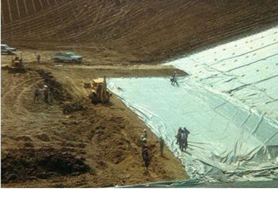


>")


>")