Download presentation
Presentation is loading. Please wait.

1
BARTOSZEK ENGINEERING 1 The Design of the Booster Collimators Larry Bartoszek BARTOSZEK ENGINEERING 3/10/03

2
BARTOSZEK ENGINEERING 2 Outline of Slides l Overview of Collimators in Booster l Details of vacuum liner design l Details of shielding design l Details of remotely operated stand design

3
One of the Two Collimators in Long 6

6
BARTOSZEK ENGINEERING 6 An issue exposed by the end view l Some unistrut supports may have to be shortened or moved away from collimator locations to allow full range of motion of collimator. l This job is not a problem and can be done in advance of the installation at any short shut-down.

7
BARTOSZEK ENGINEERING 7 Details of the vacuum liner l Construction is from two pieces of stainless steel angle welded together to form a square aperture 3” X 3” l Upstream end is tapered to avoid a hot spot

8
Fully assembled and welded vacuum liner

9
Upstream end block made transparent to expose taper

10
BARTOSZEK ENGINEERING 10 Details of Shielding Blocks l Most commonly available maximum thickness of plain carbon steel is 8 inches. l Blocks are made up of 8” and 4” thick steel plates welded together. l Machining is minimized. l No horizontal cracks within the height of the vacuum liner

11
Vacuum liner laid in lower block

12
Notch for upstream end of liner which is slightly larger than the rest Lower Block, 6.3 tons

13
Notch in the upper block for tapered end Upper Block, 5.2 tons

14
Upper and Lower Shielding Blocks Assembled with Vacuum Liner (no fasteners shown), 11.6 tons
, 11.6 tons")
15
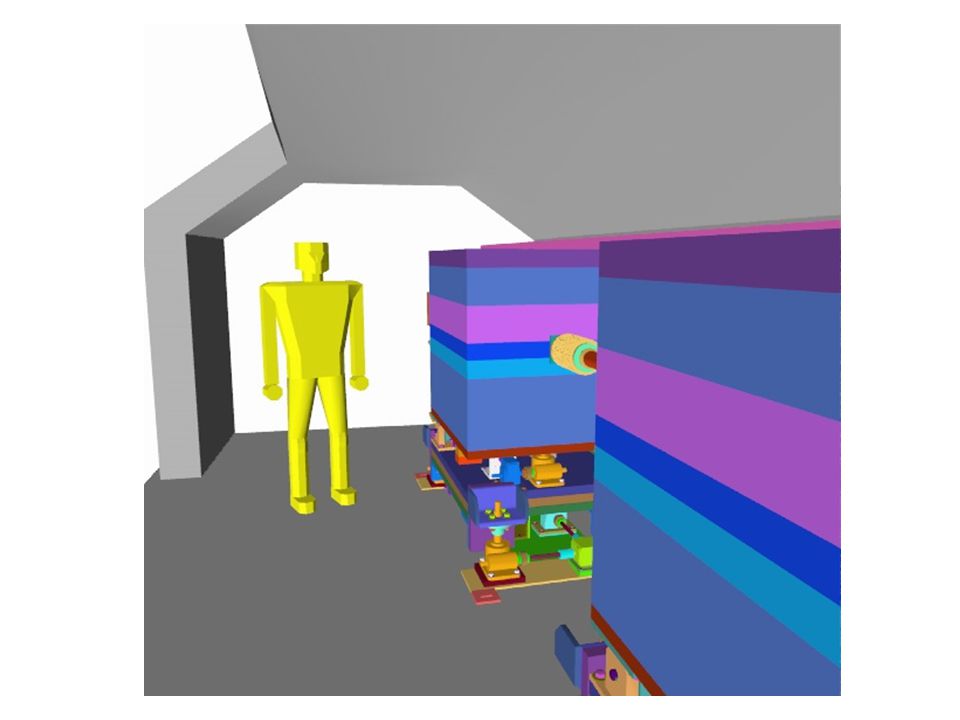
One complete collimator with stand, 14.6 tons total

16
BARTOSZEK ENGINEERING 16 Details of Stand Design l Four Separate Degrees of Freedom »Vertical »Horizontal »Yaw »Pitch l All four DOF motorized with stepper motors l Stand weighs 3 tons

17
The vertical drive system Are these sufficient?

18
BARTOSZEK ENGINEERING 18 Details of the Vertical Drive l 170 Volt motor drive system, 900 RPM max speed l 4 10 ton screw jacks l Hub City Model 261 Single Reduction Worm Gear Reducer, 40:1 ratio l ± 1.5 inches of travel,.63 inches/minute l Roller Chain couplings for manual alignment

19
Horizontal Drive Base Plate Bearing pads for sliding key

20
Horizontal base plate assembled to Vertical Drive

21
BARTOSZEK ENGINEERING 21 Details of the Horizontal Drive l 48 Volt motor drive, 900 RPM max l Single 5 ton jack, traveling nut style, drives yaw base plate horizontally l ± 1.5 inches of travel, 1.7 inches/minute l Hub City model 131, 15:1 ratio l Horizontal motion guided by bronze keys

22
Yaw Base plate assembled to horizontal drive base

23
BARTOSZEK ENGINEERING 23 Issue of stand structure l Does each layer of the base have to be attached to the one below such that the stand can be lifted in toto from the top plate? »Currently the vertical and horizontal drives are constrained but the yaw and pitch are not »These features can be added if needed

24
Close-up of flanged bushing holding the horizontal drive together (yaw base plate transparent)
")
25
Bottom view of horizontal drive showing jack, motor, reducer, etc.

26
Pitch-Yaw plate assembled to Yaw Base Plate Yaw Drive Pitch Drive

27
BARTOSZEK ENGINEERING 27 Details of Yaw Drive l 48 Volt motor drive l 5 ton jack on double clevis arrangement l Hub City Model 131, 15:1 reduction l Stroke is ± 10 milliradians, 1.7 inches/minute linear speed, ±.171 inches linear travel

28
Close-up of Yaw Drive

29
Top Plate assembled to Pitch-Yaw Plate

30
BARTOSZEK ENGINEERING 30 Details of Pitch Drive l 170 Volt motor drive l Single 10 ton jack with custom pusher block l Hub City model 211, 15:1 reducer l ±10 milliradians, ±.353 inches of linear stroke, 1.7 inches/minute

31
Top Plate made transparent

32
Side view showing pocket for Pitch Pusher Block

33
BARTOSZEK ENGINEERING 33 Diagram of Stand Degrees of Freedom l Yaw axis of rotation intersects beam line at upstream end of stand l Pitch axis intersects yaw axis below the beam line l Need to make small corrections to vertical height for pitch changes

Similar presentations


, Robert Erck (ES),>")

