Download presentation
Presentation is loading. Please wait.

1
Wisconsin DOT Facilities Development Manual (FDM)
Weston Philips 1/27/05

2
Superelevation Vertical Alignment

3
Superelevation

4
A different angle on superelevation?
Ch. 3 Elements of Design In Horizontal Alignment Section p. 173 Ch. 2 Alignments Section 2A-2, 2A-3

5
Axis of Rotation Rotate pavement about centerline
Rotate about inner edge of pavement Rotate about outside edge of pavement Rotate about center of median (Divided)
")
6
Axis of Rotation

7
Axis of Rotation

8
Superelevation Profile
Two-Lane Highway – Centerline Rotation

9
Normal Crown

10
Tangent Runout/Crown Runoff
Horizontal

11
Superelevation Runoff
Superelevation = Cross Slope

12
Superelevation Achieved

14
Max Superelevation Rate
Nomograph (Discussed Later)
")
15
Max Superelevation Rate Cont’d

16
How to Calculate Superelevation
Using Superelevation Tables Nomographs Simple Curve Formula

17
Superelevation Option 1
Given: VD = 40 mph R = 700 ft. fmax = (from Table 7) First solution is obtained from the superelevation tables, emax = 0.04 (Figure 9) R = 700.; e = 0.039 3.9% Note: Choose Table emax = 0.04
 First solution is obtained from the superelevation tables, emax = 0.04 (Figure 9) R = 700.; e = % Note: Choose Table emax =")
18
Iowa has ramp tables.

20
Minimum Radius Greenbook p. 145 (186 pdf) Minimum Radius Table
 Minimum Radius Table")
21
Superelevation Option 2
Radius 700 feet e = -2.5% 40mph

22
Note: Greenbook contains derivation of equations/graphs.

23
Superelevation Option 3
Third solution is obtained from the simplified curve formula: e = (VD2/15R) - fmax (English version) e = (402/15*700) = = -2.56% Where: VD = design speed R = radius e = superelevation rate fmax= maximum side friction. Note: Metric Version e = (VD2/127R) - fmax (metric version).
 - fmax (English version) e = (402/15*700) = = % Where: VD = design speed. R = radius. e = superelevation rate. fmax= maximum side friction. Note: Metric Version. e = (VD2/127R) - fmax (metric version).")
24
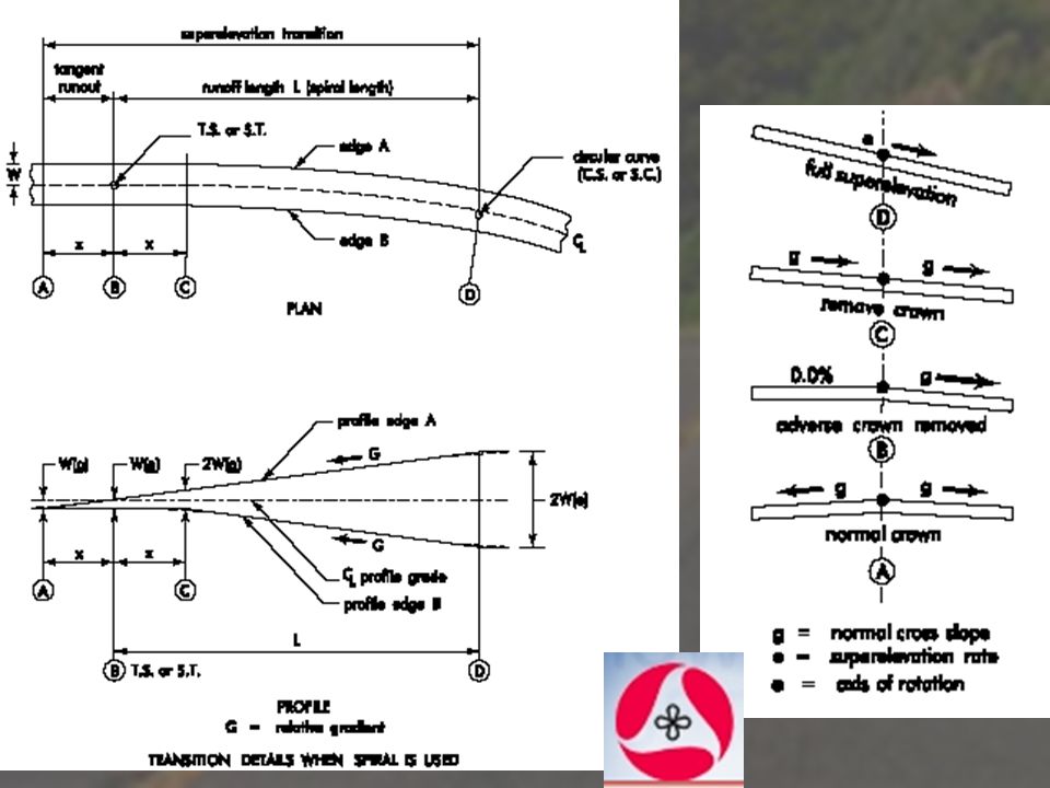
Superelevation Transition
Superelevation transition is the length required to rotate the cross slope of a highway from a normal crowned slope to a fully superelevated cross slope.

25
Transition Placement WisDOT practice is to place the tangent runout and approximately two-thirds of the length of runoff on the tangent approach and one-third of the length of runoff on the curve.

26
Calculations Compute the theoretical point of normal crown and the theoretical point of full superelevation. Given: PC = Station L = 115 ft. (Table 7, 40mph design speed) X = L * NC/ e = 115 * .02/.02 = 115ft Theoretical point of normal crown PC - 2/3L - X = = Station Theoretical point of full superelevation PC + 1/3L = = Station Where: PC = Point of Curvature L = Length of Runoff X = Length of Tangent Runout NC = Normal Crown of 2%
 X = L * NC/ e = 115 * .02/.02 = 115ft. Theoretical point of normal crown. PC - 2/3L - X = = Station Theoretical point of full superelevation. PC + 1/3L = = Station Where: PC = Point of Curvature. L = Length of Runoff. X = Length of Tangent Runout. NC = Normal Crown of 2%")
27
Length of Runoff (L)
")
28
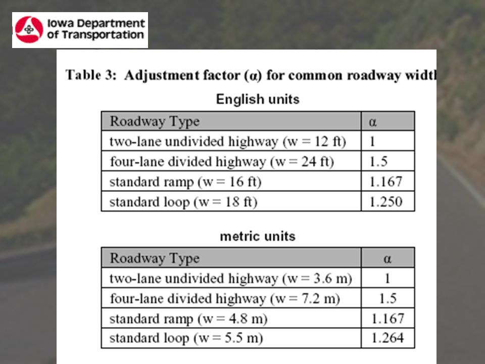
Length of Runoff (L) The adjustment factor (α) is used to adjust for different roadway widths.
 The adjustment factor (α) is used to adjust for different roadway widths.")
30
Length of Runoff (L) Greenbook p. 171 (pdf 212)
 Greenbook p. 171 (pdf 212)")
31
Tangent Runout Lt or X

32
Tangent Runout Lt or X

33
Tangent Runout Lt or X

34
Tangent Runout Lt or X

35
Vertical Alignment

36
The highway vertical alignment consists of tangents or grades and vertical curves.
Design vertical curves to provide adequate sight distance, safety, comfortable driving, good drainage, and pleasing appearance.

37
No Vertical Curves? “Although grade changes without a vertical curve are discouraged, there may be situations where it is necessary.” “Some rounding of the deflection point is anticipated during construction.”

38
Max % Grade By Functional Class

39
K Vertical Curves Vertical curves are generally
identified by their K values. K is the rate of curvature and is defined as the length of the vertical curve divided by the algebraic difference in grade Note: For Drainage, use K > 167 K

40
Question: Is there more on Vertical Alignment in the Wisconsin Manual?
p. 235 (276 pdf)
")
Similar presentations


>")


>")
 You learned how to lay out a vertical curve, given grades, PVC, PVI, and PVT in CE113 Surveying.>")


