Download presentation
Presentation is loading. Please wait.

1
Legacy Voice World Chapter 03

2
Analog Connectivity What is analog connectivity Electric wave forms Understanding Analog signaling

3
Thomas Edison Record player Braille Home telephone lines Analog phone lines electricity for voice transmission

4
As you speak Analog to digital Properties of electricity as used to convey properties of voice Digital to analog

5
Signaling When receiver is on-hook, circuit is broken - Battery at the CO + - Loop Tip Ring

6
Signaling When receiver is off-hook, circuit is complete This is an example of loop start - Battery at the CO + - Loop Tip Ring

7
Signaling This is an example of Ground start Off-hook signal accomplished by temporarily grounding the ring wire Stops GLARE - Battery at the CO + - Loop Tip Ring PBX

8
Signaling over Analog Lines On-hook Off-hook Ringing – Ringing is sent using AC current rather than DC

9
When receiver is on-hook, circuit is broken 1.True 2.False

10
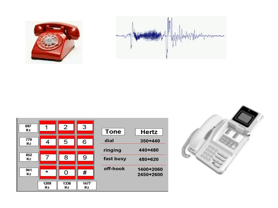
Additional Signaling Dual tone Busy Ring back Congestion Re-ordering Receiver off-hook No such number Confirmation And more

11
Address Signaling Pulse (70% connected and 30% broken connection) DTMF (dual tone multi-frequency)
 DTMF (dual tone multi-frequency)")
12
DTMF works on 1.Only analog phones 2.Only on digital phones 3.Both analog and digital phones 4.Neither analog or digital phones

13
What Did We Learn? What is analog connectivity Electric wave forms Understanding Analog signaling

14
Historical Voice Problems with Analog connection Converting Analog to Digital Converting Digital to Analog

15
Wiring a Problem Distance is prohibitive for analog wiring Requires -2 wire system Repeater CO

16
Analog phone wiring requires 1.One wire 2.Two wire 3.Three wire 4.Four wire

17
Sample Voice Nyquist: If you sample at twice the highest frequency, you can accurately reconstruct a signal digitally Common frequencies: – Human hearing 20-20,000Hz – Human speech 200-9,000Hz – Nyquist therum 300-4000Hz

18
Quantizing the Sample PAM – Pulse Amplitude Modulation

19
Human hearing range is 20 - 20,000Hz. Nyquist theory is what range? 1.20 – 20000Hz 2.200 – 20000Hz 3.200 – 9000Hz 4.300 – 4000Hz

20
Convert the Sample to Binary A-Law U-Law (US, Canada, Japan) 0110011 Both use the first bit to represent “+” or “–” amplitude A-Law uses “1” for Positive and “0” for negative U-Law uses “0” for Positive and “1” for negative Both use the next three bits for segments Both use the following three bits for the interval U-Law is known as Transcoding
 Both use the first bit to represent + or – amplitude A-Law uses 1 for Positive and 0 for negative U-Law uses 0 for Positive and 1 for negative Both use the next three bits for segments Both use the following three bits for the interval U-Law is known as Transcoding")
21
Consider the bit string 1011011… This represents a positive notation for ___ 1.A-Law 2.U-Law

22
Once in Binary Optionally compress the Samples – Send all the samples – Send just the changes – Build a code bank *standard voice sample: 64kbps (G.711) *common compressed value: 8 kbps (G.729)
 *common compressed value: 8 kbps (G.729)")
23
Which codec provides the best QoS? 1.G.729 2.G.726 3.G.723 4.G.711

24
What did we Learn? Problems with Analog connection Converting Analog to Digital Converting Digital to Analog

25
Multiple Calls on a single Pair of Wires Solve the wiring problem: TDM Understand T1, E1, and CAS specifications Understand T1, E1, and CCS specifications

26
TDM Carries multiple conversations over a 4 wire path Build wire channels called DS0s Each channel gives a time slot to transmit Common DS0 Groups: – T1 (24 DS0 frames) – E1 (32 DS0 frames_) PBX 12 412 412 412 4
 – E1 (32 DS0 frames_) PBX")
27
Analog Signals are Electrical Frequencies Once voice is digitized – signals must be 1s & 0s There are two methods: – CAS (Channel Associated Signaling) – CCS (Common Channel Signaling)
 – CCS (Common Channel Signaling)")
28
CAS in a T1 Environment (RBS) Robbed Bit Signaling The least significant bit in each 6 th frame is signaling Frame Channel - - - Channel 1st2 nd 3rd4th- - -24th 1DS0 fDS0 2DS0 3 4 5 6DS0s
 Robbed Bit Signaling The least significant bit in each 6 th frame is signaling Frame Channel Channel 1st2 nd 3rd4th th 1DS0 fDS0 2DS DS0s")
29
The previous chart represents ____ in a T1 environment 1.CCS 2.RBS 3.SS7

30
Quality and Robbed Bits The 6 th frame missing a bit degrades quality T1 can send Large frames of 193 bits at a time T1 Frame bit is in the first bit in DS0 24 T1 has two framing types: – Super framing (SF): sends 12 T1 frames at a time – Extended superframes (ESF): send 24 T1 frames at a time F6, F12 and F18, F24 (frames referenced as “A,B,C,D”)
: sends 12 T1 frames at a time – Extended superframes (ESF): send 24 T1 frames at a time F6, F12 and F18, F24 (frames referenced as A,B,C,D )")
31
CAS in an E1 Environment CAS has dedicated frames and signaling in separate channels CAS E1 has 32 channels Ch1 – dedicated to framing Ch17 – dedicated to signaling Chs 2 - 16 and 18 - 32 are dedicated to voice E1 is contra-intuitive ; called CAS since each time a slot is signaled it matches to a voice channel It is compatible with T1 CAS (has the same ABCD signaling format

32
Bundling Channels Together on a T1 and E1 Connection CCS (Common Channel Signaling) is simpler than CAS CCS dedicates a signaling channel on T1 and E1 Allows for the use of a signal protocol rather than just four bits of signaling per channel – Allows for more clmplex signaling messages – Allows for proprietary signaling messages – Most common signaling protocol is ISDN’s Q.931 – Other signaling protocols exist such as SS7 Signaling Channel: – T1 signaling channel 24 – E1 signaling channel 17
 is simpler than CAS CCS dedicates a signaling channel on T1 and E1 Allows for the use of a signal protocol rather than just four bits of signaling per channel – Allows for more clmplex signaling messages – Allows for proprietary signaling messages – Most common signaling protocol is ISDN’s Q.931 – Other signaling protocols exist such as SS7 Signaling Channel: – T1 signaling channel 24 – E1 signaling channel 17")
33
What Did We Learn? Multiple Calls on a single Pair of Wires Solve the wiring problem: TDM Understand T1, E1, and CAS specifications Understand T1, E1, and CCS specifications

34
PSTN Components of the PSN Difference between PBX and Key Systems PSTN Numbering Plans

36
PSTN Components Analog telephone Local loop Central Office (CO) Trunks (SS7) Trunks (CAS) PBX Digital Phones
 Trunks (SS7) Trunks (CAS) PBX Digital Phones")
37
Trunks

38
Which of the following is not a PSTN component 1.Analog telephone 2.PBX 3.CAS Trunks 4.Router 5.SS7 Trunks 6.Central office 7.Local loop

39
Offices PBX and Key Systems – Typical digital PSTN connection (T1 & E1) – Provide each user unique extension number – Support a large number of features Key Systems – Typically Analog PSTN connection – Users share lines between phones – Support smaller number of features
 – Provide each user unique extension number – Support a large number of features Key Systems – Typically Analog PSTN connection – Users share lines between phones – Support smaller number of features")
40
PSTN Dialing Plan PSTN number plan managed under ITU-T E-164 standard Country National description code Subscriber number North American Numbering Plan (NANP) Country code Area code Central office code Subscriber code 1-555-510-3001 (NANP)
 Country code Area code Central office code Subscriber code (NANP)")
41
Country code - Area code - Central office code - Subscriber code This numbering plan represents 1.E.164 2.NANP 3.Both 4.None of the above

42
What Did We Learn? Components of the PSN Difference between PBX and Key Systems PSTN Numbering Plans

43
Cisco Components of the Voice Networks Cisco infrastructure model Cisco Call Processing Cisco applications options

44
The Infrastructure Model

45
Call Processing: UC500 Supports 8 to 48 IP phones Integrated Voice main and Auto-attendant External MOH FX0 modules for external Analog phones FX1 modules for analog phone connections Routing/NAT support support VPN support Opt 802.11 wireless

46
Step above UC500 – CME Supports more features than UC500 Voice mail support added through (CUE) Cisco Unity Express Runs on Cisco ISRs Mostly CLI configuring
 Cisco Unity Express Runs on Cisco ISRs Mostly CLI configuring")
47
Infrastructure Parts 1.End Points 2.Hardware 3.Applications 4.Infrastructure 5.Call processing

48
Cisco Routers CiscoMax IP phonesMax SIP phones 280125 28113525 282150 2851100 : 3845250

49
Business Edition Provide scalability to 500 IP phones Combines three applications into one – CCM (Cisco Communications Manager) – Cisco Unity Communications – Cisco Unified mobility Fantastic but NO REDUNDANCY
 – Cisco Unity Communications – Cisco Unified mobility Fantastic but NO REDUNDANCY")
50
Full Blown Call Manager (CUCM) Scales to 60,000 IP phones per cluster Multi-server redundancy Multi-site support $$$
 Scales to 60,000 IP phones per cluster Multi-server redundancy Multi-site support $$$")
51
Applications Cisco Unity Express up to 100 users – Network module (NM) an advan integration module (AIM) – Lenix based, IVR, Voicemail from email, WEB, phone Cisco Unity Connection up to 500 users – 7500 users with dedicated servers – Advanced call routing rules – NO redundancy Cisco Unity (7500 users per server) – Integrated with Microsoft Exchange, lotus notes, Novell Groupwise – Redundant multiple servers
 an advan integration module (AIM) – Lenix based, IVR, Voic from , WEB, phone Cisco Unity Connection up to 500 users – 7500 users with dedicated servers – Advanced call routing rules – NO redundancy Cisco Unity (7500 users per server) – Integrated with Microsoft Exchange, lotus notes, Novell Groupwise – Redundant multiple servers")
52
Other Applications IVR (Integrated Voice Response) Unified Contact Center Express Unified Meeting Plan Unified Mobility Emergency Responders
 Unified Contact Center Express Unified Meeting Plan Unified Mobility Emergency Responders")
53
What is the problem with a UC500 1.No unified mobility 2.No analog phone support 3.No redundancy 4.No unified communications

54
What Did We Learn? Components of the PSN Difference between PBX and Key Systems PSTN Numbering Plans

55
The End

Similar presentations


>")

