Download presentation
Presentation is loading. Please wait.

1
寫入 輸出紀錄(output record) 40 J 跳回CLOOP 45 LDA EOF 插入 檔案終結符號 50 STA BUFFER
Example of SIC assembler language program Line source statement 1/4 5 COPY START 1000 從輸入到輸出 10 FIRST STL RETADR 儲存並回傳位址 15 CLOOP JSUB RDREC 讀取輸入紀錄 20 25 LDA COMP LENGTH ZERO 測試檔案是否到EOF EOF = 0 ? 30 JEQ ENDFIL EOF = 0則離開 35 WRREC 寫入 輸出紀錄(output record) 40 J 跳回CLOOP 45 LDA EOF 插入 檔案終結符號 50 STA BUFFER 55 THREE 把EOF長度設為3 60 LENGTH 65 寫入 EOF 70 LDL 取得回傳位址 75 RSUB 回到 原呼叫程式(caller)
 40. J. 跳回CLOOP. 45. LDA. EOF. 插入 檔案終結符號. 50. STA. BUFFER. 55. THREE. 把EOF長度設為 LENGTH. 65. 寫入 EOF. 70. LDL. 取得回傳位址. 75. RSUB. 回到 原呼叫程式(caller)")
2
SUBROUTINE TO READ RECORD INTO BUFFER (呼叫副程式讀取紀錄到暫存區)
Example of SIC assembler language program 2/4 80 EOF BYTE C’EOF’ 85 THREE WORD 3 90 ZERO 95 RETADR RESW 1 100 LENGTH 105 BUFFER RESB 4096 110 . 4096 byte 的暫存區 115 . 120 . SUBROUTINE TO READ RECORD INTO BUFFER (呼叫副程式讀取紀錄到暫存區) ZERO ZERO 清除迴圈計數器 把AX暫存器設為0 125 RDREC LDX 130 LDA
 ZERO ZERO. 清除迴圈計數器 把AX暫存器設為 RDREC LDX. 130 LDA.")
3
135 RLOOP TD INPUT 測試輸入裝置 140 JEQ 執行迴圈直到輸入資料 145 RD 讀取字元到AX暫存器 150
Example of SIC assembler language program 3/4 135 RLOOP TD INPUT 測試輸入裝置 140 JEQ 執行迴圈直到輸入資料 145 RD 讀取字元到AX暫存器 150 COMP ZERO 是否為紀錄結尾(EOR=0) 155 EXIT 成立的話離開迴圈 160 STCH BUFFER,X 儲存字元(X)到暫存區 165 TIX MAXLEN 執行迴圈直到紀錄的 170 JTL 最大長度 175 STX LENGTH 儲存紀錄長度 180 RSUB 回到原呼叫程式 185 BYTE X’F1’ 輸入 裝置的編碼 190 WORD 4096
 155. EXIT. 成立的話離開迴圈 STCH. BUFFER,X. 儲存字元(X)到暫存區 TIX. MAXLEN. 執行迴圈直到紀錄的 JTL. 最大長度 STX. LENGTH. 儲存紀錄長度 RSUB. 回到原呼叫程式 BYTE. X’F1’ 輸入 裝置的編碼 WORD")
4
SUBROUTINE TO WRITE RECORD INTO BUFFER 205 (呼叫副程式寫入紀錄到暫存區) 210 WRREC
Example of SIC assembler language program 4/4 195 . 200 SUBROUTINE TO WRITE RECORD INTO BUFFER 205 (呼叫副程式寫入紀錄到暫存區) 210 WRREC LDX ZERO 清除迴圈計數器 215 WLOOP TD OUTPUT 測試輸入裝置 220 JEQ 執行迴圈直到輸入資料 225 LDCH BUFFER,X 讀取暫存器(X)內容到暫存區 230 WD 輸出字元 235 TIX LENGTH 執行迴圈直到所有字元寫完 240 JLT 245 RSUB 回到原呼叫程式 250 BYTE X’05’ 255 END FIRST 輸出 裝置的編碼
 210. WRREC. LDX. ZERO. 清除迴圈計數器 WLOOP. TD. OUTPUT. 測試輸入裝置 JEQ. 執行迴圈直到輸入資料 LDCH. BUFFER,X. 讀取暫存器(X)內容到暫存區 WD. 輸出字元 TIX. LENGTH. 執行迴圈直到所有字元寫完 JLT RSUB. 回到原呼叫程式 BYTE. X’05’ 255. END. FIRST 輸出 裝置的編碼.")
5
Line 5 Loc 1000 Source statement COPY START 1000 object code 10
Object code of SIC assembler language program 1/4 Line 5 Loc 1000 Source statement COPY START 1000 object code 10 FIRST STL RETADR 141033 15 1003 CLOOP JSUB RDREC 482039 20 1006 LDA LENGTH 001036 25 1009 COMP ZERO 281030 30 100C JEQ ENDFIL 301015 35 100F JSUB WRREC 482061 40 1012 J CLOOP 3C1003 45 1015 ENDFIL LDA EOF 00102A 50 1018 STA BUFFER 0C1039 55 101B LDA THREE 00102D 60 101E STA LENGTH 0C1036 65 1021 70 1024 LDL RETADR 081033 75 1027 RSUB 4C0000

6
SUBROUTINE TO HEAD RECORD INTO BUFFER 120 125 2039
Object code of SIC assembler language program 2/4 80 102A EOF BYTE C’EOF’ 454F46 85 102D THREE WORD 3 000003 90 1030 ZERO 000000 95 1033 RETADR RESW 1 100 1036 LENGTH 105 1039 BUFFER RESB 4096 110 . 115 SUBROUTINE TO HEAD RECORD INTO BUFFER 120 125 2039 RECORD LDX ZERO 130 203C LDA ZERO

7
135 203F RLOOP TD INPUT E0205D 140 2042 JEQ 30203F 145 2045 RD D8205D
Object code of SIC assembler language program 3/4 135 203F RLOOP TD INPUT E0205D 140 2042 JEQ 30203F 145 2045 RD D8205D 150 2048 COMP ZERO 281030 155 204B EXIT 302057 160 204E STCH BUFFER,X 549039 165 2051 TIX MAXLEN 2C205E 170 2054 JTL RLOOP 38203F 175 2057 EXIT STX LENGTH 101036 180 205A RSUB 4C0000 185 205D INPUT BYTE X’F1’ F1 190 205E WORD 4096 001000

8
SUBROUTINE TO WRITE RECORD INTO BUFFER 205 210 2061
Object code of SIC assembler language program 4/4 195 . 200 SUBROUTINE TO WRITE RECORD INTO BUFFER 205 210 2061 WRREC LDX ZERO 215 2064 WLOOP TD OUTPUT E02079 220 2067 JEQ 302064 225 206A LDCH BUFFER,X 509039 230 206D WD DC2079 235 2070 TIX LENGTH 2C1036 240 2073 JLT 382064 245 2076 RSUB 4C0000 250 2079 BYTE X’05’ 05 255 END FIRST

13
Assembler language program (Fig.2.1)
Algorithm of assembler (Fig.2.4) Object program Assembly listing for (Fig.2.3) debugging (Fig.2.2)
 Object program. Assembly listing for. (Fig.2.3) debugging (Fig.2.2)")
14
1000 Intermediate file 5 COPY START 1000 Fig.2.1 Fig.2.4(a)
begin read first input line if OPCODE = 'START' then begin save #[OPERAND] as starting address initialize LOCCTR to starting address write line to intermediate file read next input line end {if START} else initialize LOCCTR to 0 Fig.2.4(a) LOCCTR=1000 COPY START 1000 Intermediate file
 LOCCTR=1000. COPY. START Intermediate file.")
15
FIRST 10 STL RETADR Fig.2.1 Fig.2.4(a) (FIRST,1000) FIRST STL RETADR
while OPCODE <> 'END' do begin . insert (LABEL.LOCCTR) into SYMTAB if found then add 3 {instruction length} to LOCCTR write line to intermediate file read next input line end {while} Fig.2.4(a) (FIRST,1000) FIRST STL RETADR LOCCTR=1003 Intermediate file
 into SYMTAB. if found then. add 3 {instruction length} to LOCCTR. write line to intermediate file. read next input line end {while} Fig.2.4(a) (FIRST,1000) FIRST STL RETADR. LOCCTR=1003. Intermediate file.")
16
15 CLOOP JSUB RDREC Fig.2.1 Fig.2.4(a) (CLOOP,1003) CLOOP JSUB RDREC
while OPCODE <> 'END' do begin . insert (LABEL.LOCCTR) into SYMTAB if found then add 3 {instruction length} to LOCCTR write line to intermediate file read next input line end {while} Fig.2.4(a) (CLOOP,1003) CLOOP JSUB RDREC LOCCTR=1006 Intermediate file
 into SYMTAB. if found then. add 3 {instruction length} to LOCCTR. write line to intermediate file. read next input line end {while} Fig.2.4(a) (CLOOP,1003) CLOOP JSUB RDREC. LOCCTR=1006. Intermediate file.")
17
20 LDA LENGTH Fig.2.1 Fig.2.4(a) LOCCTR=1009 LDA LENGTH
while OPCODE <> 'END' do begin . if found then add 3 {instruction length} to LOCCTR write line to intermediate file read next input line end {while} Fig.2.4(a) LOCCTR=1009 LDA LENGTH Intermediate file
 LOCCTR=1009. LDA LENGTH. Intermediate file.")
18
Fig.2.4(a) Intermediate file 80 85 90 Fig.2.1 EOF THREE ZERO
BYTE C’EOF’ WORD 3 WORD 0 Fig.2.1 while OPCODE <> 'END' do begin . insert (LABEL.LOCCTR) into SYMTAB else if OPCODE = 'WORD' then add 3 to LOCCTR else if OPCODE = 'BYTE' then begin find length of constant in bytes add length to LOCCTR end write line to intermediate file read next input line end {while} Fig.2.4(a) (EOF , 102A) EOF BYTE C’EOF’ WORD 3 WORD 0 (THREE ,102D) THREE LOCCTR=1030 (ZERO , 1030) LOCCTR=1033 ZERO Intermediate file
 into SYMTAB. else if OPCODE = WORD then add 3 to LOCCTR. else if OPCODE = BYTE then begin. find length of constant in bytes add length to LOCCTR. end. write line to intermediate file. read next input line end {while} Fig.2.4(a) (EOF , 102A) EOF. BYTE C’EOF’ WORD 3. WORD 0. (THREE ,102D) THREE. LOCCTR=1030 (ZERO , 1030) LOCCTR=1033. ZERO. Intermediate file.")
19
Function of algorithm for pass_1 of assembler
(1)Assign address to all statements in the program (2)Save the values (address) assigned to all labels (3)Perform some processing of assembler directives
Assign. address to all statements in the. program. (2)Save the values (address) assigned to all labels. (3)Perform. some processing of assembler. directives.")
20
5 10 intermediate file 5 10 Fig2.4(b) . (RETADR , 1033) . COPY FIRST
START STL 1000 RETADER intermediate file Pass 2 : begin read first input line {from intermediate file} if OPCODE = 'START' then begin … end{if start} write Header record to obect program initialize first Text record while OPCODE ≠ 'END' do ……….. write listing line read next input line end {while} write last Text record to object program end {pass 2} Fig2.4(b) 5 10 HCOPY A 1000 COPY START 1000 1000 FIRST STL RETADR T 141033 Fig2.2
 HCOPY A COPY START FIRST STL RETADR. T Fig2.2.")
21
Assembler language program (Fig.2.1)
Algorithm of assembler (Fig.2.4) Object program Assembly listing for (Fig.2.3) debugging (Fig.2.2)
 Object program. Assembly listing for. (Fig.2.3) debugging (Fig.2.2)")
22
Object Program correspond to Fig 2.2 case1
Line Loc Source statement 5 1000 COPY START 1000 Pass 2 Fig2.4(b) SYMTAB (LOCCTR-starting address) = length H COPY A
 SYMTAB. (LOCCTR-starting address) = length. H COPY A.")
23
Object Program correspond to Fig 2.2 case2
Line Loc Source statement FIRST STL RETADR Pass 2 Fig2.4(b) Instruction Table SYMTAB ( LABEL LOCCTR ) RETADR 1033 141033
 Instruction. Table. SYMTAB. ( LABEL LOCCTR ) RETADR")
24
Object Program correspond to Fig 2.2 case3
Line Loc Source statement 80 102A EOF BYTE C’EOF’ character Pass 2 Fig2.4(b) else if OPCODE = 'BYTE' or 'WORD' then convert constant to object code 454F46
 else if OPCODE = BYTE or WORD then convert constant to object code. 454F46.")
25
Object Program correspond to Fig 2.2 case4
Line Loc Source statement 85 102D THREE WORD 3 Pass 2 Fig2.4(b) else if OPCODE = 'BYTE' or 'WORD' then convert constant to object code 000003
 else if OPCODE = BYTE or WORD then convert constant to object code")
26
Object Program correspond to Fig 2.2 case5
Line Loc D Source statement INPUT BYTE X’F1’ hexadecimal Pass 2 Fig2.4(b) else if OPCODE = 'BYTE' or 'WORD' then convert constant to object code F1
 else if OPCODE = BYTE or WORD then convert constant to object code. F1.")
27
Object Program correspond to Fig 2.2 case6
Line Loc E Source statement MAXLEN WORD 4096 Pass 2 Fig2.4(b) else if OPCODE = 'BYTE' or 'WORD' then convert constant to object code 4096 = 212 001000
 else if OPCODE = BYTE or WORD then convert constant to object code =")
28
Object Program correspond to Fig 2.2 case7
Line Loc Source statement 255 END FIRST SYMTAB Pass 2 Fig2.4(b) ( LABEL LOCCTR ) FIRST 1000 E
 ( LABEL LOCCTR ) FIRST E")
29
Object Program correspond to Fig 2.2
HCOPY A T E C A 0C D T 00101E 15 0C C F 000000 T E E0205D 30203F D8205D C205E 38203F T C C0000 F E DC2079 2C1036 T C E Fig 2.3

30
2.2 Machine-dependent assembler
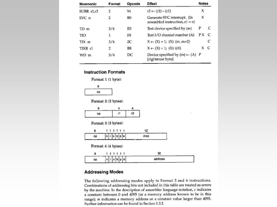
2.2.1 Instruction Formats and Address Modes START statement now specifies beginning program address of 0. As we discuss in the next section, this indicates a relocatable program.

31
2.2 Machine-dependent assembler
(1) Addressing mode symbols: @ : indirect addressing mode 70 95 RETADR RESW 1 # : immediate addressing mode 55 LDA #3 + : extended instruction format 15 CLOOP +JSUB RDREC
 Addressing mode : indirect addressing mode RETADR RESW 1. # : immediate addressing mode. 55 LDA #3. + : extended instruction format. 15 CLOOP +JSUB RDREC.")
32
(2) Use of register-register instructions
2.2 Machine-dependent assembler (2) Use of register-register instructions instead of register memory instructions -> improve the exaction speed of the program. CPU Memory I/O
 Use of register-register instructions. instead of register memory instructions. -> improve the exaction speed of the program. CPU Memory. I/O.")
33
2.2 Machine-dependent assembler
The conversion of register mnemonics to numbers can be done with a separate table; however, SYMTAB would be preloaded with the register names (A,X, etc.) and their values(0,1,ects.). Most of the register-to-memory-instructions are assembled using either program-counter relative or base relative addressing. Fit in the 12-bit field in the instruction Displacement must be between 0 and 4095(for base) or between and 2047(for program-counter).
 and their values(0,1,ects.). Most of the register-to-memory-instructions are assembled using either program-counter relative or base relative addressing. Fit in the 12-bit field in the instruction. Displacement must be between 0 and 4095(for base) or between and 2047(for program-counter).")
34
2.2 Machine-dependent assembler
(3) If neither program-counter relative nor base relative addressing can be used, then the 4-byte extended Instruction format must be used. =102D >1000 CLOOP +JSUB . . RDREC RDREC CLEAR X
 If neither program-counter relative nor base relative addressing can be used, then the 4-byte extended Instruction format must be used =102D > CLOOP +JSUB. . . RDREC. RDREC. CLEAR X.")
35
2.2 Machine-dependent assembler
The extend format by using the prefix + (as on line 15).addressing is applicable and extended format is not specified, then the instruction cannot be properly assembled. In this case, the assembler must generate an error message.
.addressing is applicable and extended format is not specified, then the instruction cannot be properly assembled. In this case, the assembler must generate an error message.")
36
2.2 Machine-dependent assembler
(4) Displacement calculation for program- counter relative and base addressing modes: FIRST STL RETADR Since address (RETADR) =0030 and next address (FIRST) =0003, we obtain displacement= =02D with pc relative addressing and neither indirect nor immediate addressing, the object code of this assembly instruction is 17202D Opcode (STL) 000101 n i x b p e 1 7 2
 Displacement calculation for program- counter relative and base addressing modes: FIRST STL RETADR. Since address (RETADR) =0030 and next address (FIRST) =0003, we obtain displacement= =02D with pc relative addressing and neither indirect nor immediate addressing, the object code of this assembly instruction is D. Opcode (STL) n i x b p e")
37
2.2 Machine-dependent assembler
The program counter is advanced after each instruction is fetched and before it is executed. The displacement we need in the instruction is 30 – 3 = 2D. The target address calculation performed will be (PC) + disp. 𝑝is set to 1 to indicate program-counter relative address, making the last 2 bytes of the instruction 202D.
 + disp. 𝑝is set to 1 to indicate program-counter relative address, making the last 2 bytes of the instruction 202D.")
38
2.2 Machine-dependent assembler
(5) The difference between pc relative addressing and base relative addressing is that the assembler knows what the contents of the program-counter will be at execution time but the base register is under the control of the programmer. 20 000A LDA LENGTH 100 0033 RESW 1 175 1056 EXIT STX
 The difference between pc relative addressing and base relative addressing is that the assembler knows what the contents of the program-counter will be at execution time but the base register is under the control of the programmer A. LDA. LENGTH RESW EXIT. STX.")
39
2.2 Machine-dependent assembler
Example of program-counter relative assembly is the instruction: J CLOOP 3F2FEC The programmer must tell the assembler what the base register will contain during execution of the program so that the assembler can compute displacements.

40
2.2 Machine-dependent assembler
The statement BASE LENGTH (line 13) informs the assembler that the base register will contain the address of LENGTH. (LDB #LENGTH) loads this values into the register during program execution. BASE and NOBASE are assembler directives, and produce no executable code. The programmer must provide instructions that load the proper value into the base register during execution. The target address calculation will not produce the correct operand address.
 informs the assembler that the base register will contain the address of LENGTH. (LDB #LENGTH) loads this values into the register during program execution. BASE and NOBASE are assembler directives, and produce no executable code. The programmer must provide instructions that load the proper value into the base register during execution. The target address calculation will not produce the correct operand address.")
41
2.2 Machine-dependent assembler
ESTCH BUFFER,X 57C003 The address of BUFFER is 0036.𝑥and 𝑏are set to 1 in the assembled instruction. The difference between the assembly of the instructions on lines, LDA LENGTH is assembled with program-counter. STX LENGTH uses base relative displacement required for the statement on line 175, you will see that into the 12-bit displacement field. program-counter relative assembly first.

42
2.2 Machine-dependent assembler
(6) The displacement of pc relative mode is between and but the displacement of base relative mode is between 0 and For SIC/XE assembler, it attempt pc relative mode assembly first. 20 000A LDA LENGTH 100 0033 RESW 1 175 1056 EXIT STX
 The displacement of pc relative mode is between and but the displacement of base relative mode is between 0 and For SIC/XE assembler, it attempt pc relative mode assembly first A. LDA. LENGTH RESW EXIT. STX.")
43
2.2 Machine-dependent assembler
Desirable to have more than one program at a time sharing the memory and other resources of the machine. It is not practical to plan program execution this closely. Situation the actual starting is not known until load time. Program (Fig.2.3), register A is to be loaded at address 2000 instead of address Address 102D will not contain the value that probably be part of some other user’s program.
, register A is to be loaded at address 2000 instead of address Address 102D will not contain the value that probably be part of some other user’s program.")
44
2.2 Machine-dependent assembler
Not know the actual location where the program, the assembler can identify for the loader those parts program that need modification. Modification is called a relocatable program. The program from Figs. 2.5 and 2.6. This program loaded beginning at address 0000. The program beginning at address 7420 (Fig. 2.7),would need to be changed to 4B108456, the new address of RDREC.
,would need to be changed to 4B108456, the new address of RDREC.")
45
2.2 Machine-dependent assembler
0000 5000 0006 (+JSB RDREC) 5006 (+JSB RDREC) 1036 6036 RDREC RDREC 1076 6076 . 4B106036 . . B410 (a) 7420 (b) 7426 (+JSB RDREC) 8456 RDREC 8496 Fig 2.7 Examples of program relocation (c)
 (+JSB RDREC) RDREC. RDREC B B410. (a) (b) (+JSB RDREC) RDREC Fig 2.7 Examples of program. relocation. (c)")
46
2.2 Machine-dependent assembler
RDREC is always 1036 bytes past the starting address of the program. 1.Insert the address of RDREC relative to the start of the program.(to 0 for the assembly.) 2.Add the beginning address of the program to the address field in the JSUB instruction at load time.
 2.Add the beginning address of the program to the address field in the JSUB instruction at load time.")
47
2.2 Machine-dependent assembler
(7) The kind of sharing of the common memory among programs is called multiprogramming. An object program that contains the information necessary to perform address modification is call a relocatable program. Ex. 15 CLOOP +JSUB RDREC M . 4B (CLOOP +JSUB RDREC) . B410 0000 0006 . 4B106036 . . B410 5000 5006 (RDREC CLEAR X) 1036 6036 4B101036 4B106036 M 0007 Fig 2.7
 The kind of sharing of the common memory among programs is called multiprogramming. An object program that contains the information necessary to perform address modification is call a relocatable program. Ex. 15 CLOOP +JSUB RDREC M B (CLOOP +JSUB RDREC) . B B B (RDREC. CLEAR X) B B M Fig 2.7.")
48
2.2 Machine-dependent assembler
(8) For the loader, of course, must also be a part of the object program. We can accomplish this with a Modification record having the following format: Modification record: Col. 1 M Col. 2-7 Starting location of the address field to be modified, relative to the beginning of the program. Col. 8-9 Length of the address field to be modified in half-bytes. 15 CLOOP +JSUB RDREC
 For the loader, of course, must also be a part of the object program. We can accomplish this with a Modification record having the following format: Modification record: Col. 1 M. Col. 2-7 Starting location of the address field to be modified, relative to the beginning of the program. Col. 8-9 Length of the address field to be modified in half-bytes. 15 CLOOP +JSUB RDREC.")
49
2.2 Machine-dependent assembler
The length is stored in half-bytes, modified may not occupy an integral number of bytes.(20 bits, 5 half-bytes) The location of the byte containing the leftmost bits of the address field to be modified. M (5*4=20 bits ) This record specifies that the beginning address of the program is to begin at address and is 5 half-bytes in length. The first 12 bits (4B1), the last 20 bits (01036) to produce the correct operand address.
 The location of the byte containing the leftmost bits of the address field to be modified. M (5*4=20 bits ) This record specifies that the beginning address of the program is to begin at address and is 5 half-bytes in length. The first 12 bits (4B1), the last 20 bits (01036) to produce the correct operand address.")
50
2.2 Machine-dependent assembler
Modification is needed because the operand is specified using program-counter relative or base relative addressing. Thus no instruction modification is needed. The only such direct address are found in extended format (4-byte) instructions. Almost every instruction required modification. Show the complete object program corresponding to the source program of Fig There is one Modification record field that needs to be changed when the program is relocated.
 instructions. Almost every instruction required modification. Show the complete object program corresponding to the source program of Fig There is one Modification record field that needs to be changed when the program is relocated.")
51
2.2 Machine-dependent assembler
The instructions need not be modified: the instruction operand is not a memory address. 25 COMP #0 the operand is specified using pc relative or base relative addressing. 40 J CLOOP 160 STCH BUFFER,X

52
2.2 Machine-dependent assembler
(10) The only parts of the program that require modification at load time are those that specify direct address. 15 CLOOP +JSUB RDREC M 35 WRREC M 65 WRREC M
 The only parts of the program that require modification at load time are those that specify direct address. 15. CLOOP. +JSUB. RDREC M WRREC M WRREC M")
53
2.3 Machine-independent assembler features

54
2.3 Machine-independent assembler features
Common assembler features that are not closely related to machine architecture. The implementation od literals within an assembler. The value of a constant operand as apart of the instruction that uses it. Operand is called a literal because the value. A literal is identified with the prefix =, by a specification of the literal value, using the same notation. Thus the literal in the statement 45 001A ENDFIL LDA =C’EOF’

55
2.3 Machine-independent assembler features
The notation used for literals varies from assembler to assembler; some symbol make literal identification easier. With immediate addressing, the operand value is assembled the machine instruction. The assembler generates the value as a construction at some other memory. The address is used as the target address for the machine intruction.

56
2.3 Machine-independent assembler features
Operands used in a program are gathered together into more literal pools. Pool at the end of the program. The assigned addresses and the generated data values. The assembler encounters a LTORG statement, it creates a literal pool that contains all of the literal operands used previous LTORG. Literals placed in a pool by LTORG will not be repeated in the pool at the end of the program.

57
2.3 Machine-independent assembler features
(1)Immediate addressing : the operand is assembled as part of the machine instruction. Literal addressing : the operand value is specified as a constant at some other memory location.
Immediate addressing : the operand is assembled as part of the machine instruction. Literal addressing : the operand value is specified as a constant at some other. memory location.")
58
2.3 Machine-independent assembler features
(2)The LTORG statement on line 93, the literal =C’EOF’. The instruction referencing it to allow program-counter extended format instructions when referring arises when it is desirable close to the instruction that uses it. Only one copy of the specified data value. For example, the literal =X‘05’ is used in our program on lines 230. However, one data area with this value is generated. String defining them the generated data value instead defining expression identical operand values.
The LTORG statement on line 93, the literal =C’EOF’. The instruction referencing it to allow program-counter extended format instructions when referring arises when it is desirable close to the instruction that uses it. Only one copy of the specified data value. For example, the literal =X‘05’ is used in our program on lines 230. However, one data area with this value is generated. String defining them the generated data value instead defining expression identical operand values.")
59
2.3 Machine-independent assembler features
(3)Our example program, operand with value Identical names appear in the literal pool. Ready to describe how the assembler handles literal operands needed is a literal table LITTAB. For the literal name, the operand value and length during Pass 1, the assembler searches a LTORG makes a scan of the literal. This time each literal currently in the table is assigned an address. Address are counter is updated to reflect the number of bytes occupied by each literal.
Our example program, operand with value Identical names appear in the literal pool. Ready to describe how the assembler handles literal operands needed is a literal table LITTAB. For the literal name, the operand value and length during Pass 1, the assembler searches a LTORG makes a scan of the literal. This time each literal currently in the table is assigned an address. Address are counter is updated to reflect the number of bytes occupied by each literal.")
60
2.3 Machine-independent assembler features
(4)LITTAB (literal table): Pass 1: literal->LITTAB->LTORG->address Pass 2: literal->LITTAB->address
LITTAB (literal table): Pass 1: literal->LITTAB->LTORG->address. Pass 2: literal->LITTAB->address.")
61
2.3 Machine-independent assembler features
2.3.2 Symbol-Defining Statement (1)User-define symbol we have seen in assembler as labels on instructions or data areas. A label is the address assigned to the statement on which it assembler directive that allows the programmer to define symbols and specify their values. symbol EQU value
User-define symbol we have seen in assembler as labels on instructions or data areas. A label is the address assigned to the statement on which it assembler directive that allows the programmer to define symbols and specify their values. symbol EQU value.")
62
2.3 Machine-independent assembler features
(2)The given symbol and assigns to it the value specified. Include the statement +LDT #4096 MAXLEN EQU 4096 It enters MAXLEN into SYMTAB (with value 4096), to find and change the value of MAXLEN, register-A, X, L, etc. Register numbers instead of names in an instruction like RMO include a sequence of EQU statements. To the field SYMBOL, and FLAGS individually, so we must also define these labels would be with EQU statement.
The given symbol and assigns to it the value specified. Include the statement. +LDT #4096. MAXLEN EQU It enters MAXLEN into SYMTAB (with value 4096), to find and change the value of MAXLEN, register-A, X, L, etc. Register numbers instead of names in an instruction like RMO include a sequence of EQU statements. To the field SYMBOL, and FLAGS individually, so we must also define these labels would be with EQU statement.")
63
2.3 Machine-independent assembler features
(3)Why use EQU? *It is used for improved readability in place of numeric values. *It is used for defining mnemonic names for registers. *It is used to have the standard register mnemonic built into the assembler.
Why use EQU *It is used for improved readability in place of numeric values. *It is used for defining mnemonic names for registers. *It is used to have the standard register. mnemonic built into the assembler.")
64
2.3 Machine-independent assembler features
(4)Why use ORG? *It assigns values to symbols. *It is used in label definition. *Restriction: it must have been defined previously in the program.
Why use ORG *It assigns values to symbols. *It is used in label definition. *Restriction: it must have been defined previously in the program.")
65
2.3 Machine-independent assembler features
(5)Assembler directive can be used to indirectly assign values to symbols, usually called ORG (for “origin”) ORG value The assembler resets its location counter (LOCCTR) to the specified affect the values of all labels defined until the next ORG.
Assembler directive can be used to indirectly assign values to symbols, usually called ORG (for origin ) ORG value. The assembler resets its location counter (LOCCTR) to the specified affect the values of all labels defined until the next ORG.")
66
2.3 Machine-independent assembler features
(6)The first ORG rests the location counter to the value of STAB, the current value in LOCCOR; the label on the RESW statement assigns to VALUE the address (STAB+6). The last ORG is very important, the next unassigned byte of memory after the table STAB.
The first ORG rests the location counter to the value of STAB, the current value in LOCCOR; the label on the RESW statement assigns to VALUE the address (STAB+6). The last ORG is very important, the next unassigned byte of memory after the table STAB.")
67
2.3 Machine-independent assembler features
(7)BETA cannot be assigned a value when it encountered during Pass 1 of the assembly (ALPHA does not yet have a value), two-pass assembler design requires that symbols be defined during Pass 1. BETA EQU ALPHA ALPHA RESW 1
BETA cannot be assigned a value when it encountered during Pass 1 of the assembly (ALPHA does not yet have a value), two-pass assembler design requires that symbols be defined during Pass 1. BETA EQU ALPHA. ALPHA RESW 1.")
68
2.3 Machine-independent assembler features
(8) ORG ALPHA BYTE1 RESB 1 BYTE2 RESB 1 BYTE3 RESB 1 ORG ALPHA RESB 1 Assign to the location counter in response to the first ORG statement. The symbols BYTE1, BYTE2, and BYTE3, could not be assigned addresses during Pass1.
 ORG ALPHA. BYTE1 RESB 1. BYTE2 RESB 1. BYTE3 RESB 1. ORG. ALPHA RESB 1. Assign to the location counter in response to the first ORG statement. The symbols BYTE1, BYTE2, and BYTE3, could not be assigned addresses during Pass1.")
69
2.3 Machine-independent assembler features
(9)Expressions are classified as either absolute expressions or relative expressions depending upon the type of value they produce. *Absolute expressions: relative terms occur in pairs. *Relative expressions: the remaining unpaired relative term must have a positive sign. *Example: RETADR(R),BUFFER(R),BUFEND(R),MAXLEN(A).
Expressions are classified as either absolute expressions or relative expressions depending upon the type of value they produce. *Absolute expressions: relative terms occur in pairs. *Relative expressions: the remaining unpaired relative term must have a positive sign. *Example: RETADR(R),BUFFER(R),BUFEND(R),MAXLEN(A).")
70
2.3 Machine-independent assembler features
(10)Each such expression evaluated by the assembler to produce address or value to the beginning of the program either a relative term depending upon the expression value. Absolute expressions or relative expressions of value, they produce also contain relative terms provided the relative terms in each such pair have opposite signs be adjacent to each other in the expression multiplication or division operation.
Each such expression evaluated by the assembler to produce address or value to the beginning of the program either a relative term depending upon the expression value. Absolute expressions or relative expressions of value, they produce also contain relative terms provided the relative terms in each such pair have opposite signs be adjacent to each other in the expression multiplication or division operation.")
71
2.3 Machine-independent assembler features
(11)The remaining unpaired relative term must positive that are legal under these definitions include or expression represents some value that program and r is term or expression relative to the stating address. The two addresses, which is the length of the buffer area, the symbol that appears in the statement (MAXLEN). The program starting address in a way, anything within the program itself to be of any use, they are considered type of value (absolute or relative).
The remaining unpaired relative term must positive that are legal under these definitions include or expression represents some value that program and r is term or expression relative to the stating address. The two addresses, which is the length of the buffer area, the symbol that appears in the statement (MAXLEN). The program starting address in a way, anything within the program itself to be of any use, they are considered type of value (absolute or relative).")
72
2.3 Machine-independent assembler features
(12)Program locks allow the generated machine instructions and data to appear in the object program in a different order from the corresponding source statements.
Program locks allow the generated machine instructions and data to appear in the object program in a different order from the corresponding source statements.")
73
2.3 Machine-independent assembler features
(13)The assembler directive USE indicates which portions of the source program belong to the various blocks.
The assembler directive USE indicates which portions of the source program belong to the various blocks.")
74
2.3 Machine-independent assembler features
(14)Program logically contained subroutines, areas, etc. Block of object code and object programs in a different order from corresponding source statements. Independent parts of object program refer to segments of code that are rearranged within a sing program unit, and refer to segments that are translated object program units.
Program logically contained subroutines, areas, etc. Block of object code and object programs in a different order from corresponding source statements. Independent parts of object program refer to segments of code that are rearranged within a sing program unit, and refer to segments that are translated object program units.")
75
2.3 Machine-independent assembler features
(15)Shows our example program as it might be written blocks. 92 USE CDATA 103 USE CBLKS 123 USE 183 USE CDATA The executable instructions of the program, data areas that are a few words or less areas that consist of larger blocks which portions of the source various block, program belongs to this single block of the block named CDATA statement may also indicate a continuation of a previously begun block CDATA will (logically) rearrange these together the pieces of each block.
Shows our example program as it might be written blocks. 92 USE CDATA. 103 USE CBLKS. 123 USE. 183 USE CDATA. The executable instructions of the program, data areas that are a few words or less areas that consist of larger blocks which portions of the source various block, program belongs to this single block of the block named CDATA statement may also indicate a continuation of a previously begun block CDATA will (logically) rearrange these together the pieces of each block.")
76
2.3 Machine-independent assembler features
(16)Rearrangement of code by maintaining a separate location counter for each program, initialized to 0 when the block is first begun. Each label in the program is assigned an address that is relative of the block that contains assigned relative value of the location counter for the length of that block from the information in SYMTAB. The assembler simply adds the location of the symbol, relative to the assigned block starting address. Pass 1 the assembler constructs a table that contains the starting address and lengths for all blocks.
Rearrangement of code by maintaining a separate location counter for each program, initialized to 0 when the block is first begun. Each label in the program is assigned an address that is relative of the block that contains assigned relative value of the location counter for the length of that block from the information in SYMTAB. The assembler simply adds the location of the symbol, relative to the assigned block starting address. Pass 1 the assembler constructs a table that contains the starting address and lengths for all blocks.")
77
2.3 Machine-independent assembler features
(17)During pass 1, a separate location counter for each program block and each label in the program is assigned an address that in relative to the start of the block that contains it. Block name Block number Address Length (default) 0000 0066 CDATA 1 000B CBLKS Example: 2 0071 1000 LDA LENGTH 032 ??? operand (LENGTH)=0003 start address of program block 1 (CDATA)=0066 ->Target address= =0069 ->Since pc relative addressing, the required displacement= =0060->???=060
During pass 1, a separate location counter for each program block and each label in the program is assigned an. address that in relative to the start of the block that contains it. Block name Block number Address Length. (default) CDATA B. CBLKS. Example: LDA LENGTH 032 operand (LENGTH)=0003. start address of program block 1 (CDATA)= >Target address= = >Since pc relative addressing, the required displacement= =0060-> =060.")
78
2.3 Machine-independent assembler features
(18)Program-counter relative addressing following instruction (line 25), address is simply 0009. The large buffer to the end of the object program, to use extended format instructions on line 15, 35, and 65. Furthermore, the CDATA block to be sure that the literals are placed ahead large data.
Program-counter relative addressing following instruction (line 25), address is simply The large buffer to the end of the object program, to use extended format instructions on line 15, 35, and 65. Furthermore, the CDATA block to be sure that the literals are placed ahead large data.")
79
2.3 Machine-independent assembler features
(19)It is not necessary to physically rearrange the generated code in the object program to place the pieces of each program block. The object code as it is generated during Pass 2 and address in each Text record. The first two Text records are generated from the source program line 5 through 70 on line 92 is recognized. The assembler then prepares to begin a new Text record for the new program block.
It is not necessary to physically rearrange the generated code in the object program to place the pieces of each program block. The object code as it is generated during Pass 2 and address in each Text record. The first two Text records are generated from the source program line 5 through 70 on line 92 is recognized. The assembler then prepares to begin a new Text record for the new program block.")
80
2.3 Machine-independent assembler features
(20)The separation of the program into blocks has considerably reduced the addressing problems. HCOPY... T T00001E... T T T00006C... T00004D... T00006D... T
The separation of the program into blocks has considerably reduced the addressing problems. HCOPY... T T00001E... T T T00006C... T00004D... T00006D... T")
81
2.3 Machine-independent assembler features
(21)The next two Text records come from lines 125 through 180. The Text records resumes the default program block and the rest of the object program continues in similar fashion. Text records of the object program are not sequence, the loader will simply load the object code from the indicated address locations 0000 through 0065 through 0070, CBLKS will occupy locations though CDATA(1) and CBLKS(1) are not actually present in the object, address are assigned, storage will automatically be reserved for these areas when the program is loaded.
The next two Text records come from lines 125 through 180. The Text records resumes the default program block and the rest of the object program continues in similar fashion. Text records of the object program are not sequence, the loader will simply load the object code from the indicated address locations 0000 through 0065 through 0070, CBLKS will occupy locations though CDATA(1) and CBLKS(1) are not actually present in the object, address are assigned, storage will automatically be reserved for these areas when the program is loaded.")
82
2.3.5 Control sections and program linking

83
2.3.5 Control sections and program linking
1/7 (1)A control section is a part of the program that maintains its identity after assembly. Control sections are most often used for subroutines or either logical subdivisions of a program. When control section from logically related parts of a program, it is necessary to provide some means for linking them together. A major benefit of using control sections is the resulting flexibility.
A control section is a part of the program that maintains its identity after assembly. Control sections are most often used for subroutines or either logical subdivisions of a program. When control section from logically related parts of a program, it is necessary to provide some means for linking them together. A major benefit of using control sections is the resulting flexibility.")
84
2.3.5 Control sections and program linking
When control sections from logically related of a program, might need to refer to instructions or data located in other section. Such reference between control sections are called external reference. The assembler generates information for each external reference that will allow the loader to perform the require linking.

85
2.3.5 Control sections and program linking
Figure 2.15 shows our example program, the are control sections: one for the main program and one for each subroutine. The first control until the CSECT statement on line 109 RDREC.

86
2.3.5 Control sections and program linking
2/7 (2)Control sections differ from program blocks in that they are handled separately by the assembler. The EXTDEF (external definition) statement in a control section names symbols called external symbols, that are defined in this control sections and may be used by other sections.
Control sections differ from program blocks in that they are handled separately by the assembler. The EXTDEF (external definition) statement in a control section names symbols called external symbols, that are defined in this control sections and may be used by other sections.")
87
2.3.5 Control sections and program linking
3/7 (3)The EXTREF (external reference) statement names symbols that are used in this control sections and defined elsewhere. BUFFER, BUFFND, and LENGTH are defined in the control section named COPY and the other sections by EXTDEF statement on line 6.
The EXTREF (external reference) statement names symbols that are used in this control sections and defined elsewhere. BUFFER, BUFFND, and LENGTH are defined in the control section named COPY and the other sections by EXTDEF statement on line 6.")
88
2.3.5 Control sections and program linking
4/7 (4)Example: (Fig 2.16) CLOOP +JSUB RDREC 4B100000
Example: (Fig 2.16) CLOOP. +JSUB RDREC 4B")
89
2.3.5 Control sections and program linking
The operand (RDREC) is named in EXTREF statement , so this is an external reference. Instead the assembler inserts an address of zero and passes information to the loader, the proper address at load time. Thus an extended format instruction must be used to provide room for the actual address to be inserted.
 is named in EXTREF statement , so this is an external reference. Instead the assembler inserts an address of zero and passes information to the loader, the proper address at load time. Thus an extended format instruction must be used to provide room for the actual address to be inserted.")
90
2.3.5 Control sections and program linking
5/7 (5) Note the different between the handing of the expression on line 190 and the similar expression on line 107. (Fig 2.16) MAXLEN EQU BUFEND-BUFFER MAXLEN WORD BUFEND-BUFFER
 Note the different between the handing of the expression on line 190 and the similar expression on line 107. (Fig 2.16) MAXLEN EQU BUFEND-BUFFER MAXLEN WORD BUFEND-BUFFER.")
91
2.3.5 Control sections and program linking
STCH BUFFER,X External reference to BUFFER, the 𝑥 bit is set to 1 to indicate. MAXLEN WORD BUFEND-BUFFER Involving two external reference: stores this value as zero. When the program is loading, the loader will add to this data area the address. Any attempt to refer to a symbol in another control section must be flagged as an error unless the symbol is identified (using EXTREF) as an external reference.
 as an external reference.")
92
2.3.5 Control sections and program linking
6/7 (6) The assembler must include information in the object program that will cause the loader to insert the proper values where they are required. The required types of object code format to handle external defined or external referenced symbols are Define, Refer and revised Modification.
 The assembler must include information in the object program that will cause the loader to insert the proper values where they are required. The required types of object code format to handle external defined or external referenced symbols are Define, Refer and revised Modification.")
93
2.3.5 Control sections and program linking
The two new record types are Define and Refer. External symbols that are defined in this control section. Define record: Program linking is added to the Modification record type. Modification record type: In half-bytes. Figure 2.17 shows the object program corresponding to the source in Fig for each control section.

94
2.3.5 Control sections and program linking
7/7 (7) The address field for the JSUB instruction on line 15 begins at relative address The object program is zero. The Modification record M RDREC COPY specifies that the address of RDREC is to be added to this field, thus producing the correct machine instruction for execution. COPY perform similar functions for instructions on lines 35 and 65.
 The address field for the JSUB instruction on line 15 begins at relative address The object program is zero. The Modification record. M RDREC. COPY specifies that the address of RDREC is to be added to this field, thus producing the correct machine instruction for execution. COPY perform similar functions for instructions on lines 35 and 65.")
95
2.3.5 Control sections and program linking
The last two Modification records in RDREC direct that the address of BUFEND be added to this field, and the address of BUFFER be subtracted from it, results in the desired value for the data word.

96
2.3.5 Control sections and program linking
On the other hand, if they are in different, their difference has a value that is unpredictable. The load address of the two control sections. When an expression involves external references, the assembler cannot in general determine whether or not the expression is legal. In the same control sections, the assembler evaluates all of the terms it can, and combines finish the evaluation.

97
2.4 Assembler design options

98
2.4 Assembler design options
1/8 (1)Two alternatives to the standard two- pass assembler that with overlay structure is designed to execute some of its segments overlaying others.
Two alternatives to the standard two- pass assembler that with overlay structure is designed to execute some of its segments overlaying others.")
99
2.4 Assembler design options
The main problem in trying to assemble a program involves forward reference, address to insert in the translated instruction. All such areas be defined in the source program before they are reference. The program often requires a forward jump after testing some condition. There are two main types of one-pass assembler. In memory for immediate execution of object program for later execution.

100
2.4 Assembler design options
2/8 (2)To reduce the size of the problem, many one-pass assemblers do prohibit forward references to data items.
To reduce the size of the problem, many one-pass assemblers do prohibit forward references to data items.")
101
2.4 Assembler design options
3/8 (3)There are two main types of one-pass assembler. One type produces object code directly in memory for immediate execution; the other type produces the usual kind of object program for later execution.
There are two main types of one-pass assembler. One type produces object code directly in memory for immediate execution; the other type produces the usual kind of object program for later execution.")
102
2.4 Assembler design options
4/8 (4) Load-and-go assembler: It scans source program if operand is not defined, the operand address is omitted until the definition is encountered if the value of some operand in SYMTAB is still marked with * after the completion of scanning source code, it indicate undefined symbol errors.
 Load-and-go assembler: It scans source program if operand is not defined, the operand address is omitted until the definition is encountered if the value of some operand in SYMTAB is still marked with * after the completion of scanning source code, it indicate undefined symbol errors.")
103
2.4 Assembler design options
One-pass assemblers that generate their object code in memory for immediate execution. Program is written out, and no load and go assembler is useful in a system that is oriented toward program development and testing. The overhead of writing the object program out and reading, assembler also avoids the overhead of an additional pass over the source program.

104
2.4 Assembler design options
The handing of forward references becomes less difficult. If an instruction operand is symbol that has not yet been defined, address is omitted when the instruction is assembled. This entry is flagged to indicate that the symbol is added to a list of forward references associated with table entry.

105
2.4 Assembler design options
5/8 (5) One-pass assemblers that produce object programs as output: The assembler generates another Text record with the correct operand address. When the program is loaded, this address will be inserted into the instruction by the action of the loader.
 One-pass assemblers that produce object programs as output: The assembler generates another Text record with the correct operand address. When the program is loaded, this address will be inserted into the instruction by the action of the loader.")
106
2.4 Assembler design options
Forward references are entered into lists as before. That made forward references to that system longer be available in memory for modification. The program is loaded, this address will be inserted into the instruction by the action of the loader. The definition of ENDFIL on line 45 is encountered, the assembler generates the third Text record.

107
2.4 Assembler design options
6/8 (6) Multi-pass assembler can made as many passes as are needed to process the definitions of symbols.
 Multi-pass assembler can made as many passes as are needed to process the definitions of symbols.")
108
2.4 Assembler design options
The symbol BETA cannot be assigned a value when it is encountered during the first pass because DELTA has not yet been defined. During the second, sequential passes over the source program cannot resolve such a sequence definitions. Some assemblers are designed to eliminate the need for such restrictions. For such an assembler to make over the entire program, symbol definition are saved during Pass1.

109
2.4 Assembler design options
Symbol-defining statement that involve forward reference. Symbol table entries resulting from Pass 1 process has not yet been defined, for HALFSZ is stored in the symbol table in place of its value that one symbol in the defining expression is undefined.

110
2.4 Assembler design options
BUFEND and BUFFER are entered into SYMTAB with lists indicating the dependence of MAXLEN upon them. The defining of BUFFER on line 4 lets us begin evaluation of some of these symbols. This address is stored as the value of BUFFER.

111
2.4 Assembler design options
7/8 (7)The undefined symbol is stored in the SYMTAB in the defining expression is undefined while the expression might be pointed by the SYMTAB. Symbol * identicates undefined operand. Associated with the entry of SYMTAB is a list of the symbols whose values depend on the symbols of this entry.
The undefined symbol is stored in the SYMTAB in the defining expression is undefined while the expression might be pointed by the SYMTAB. Symbol * identicates undefined operand. Associated with the entry of SYMTAB is a list of the symbols whose values depend on the symbols of this entry.")
112
2.4 Assembler design options
8/8 (8) Operation of multi-pass assembler: Defined symbol SYMTAB (&n-1) or * expression recursive operation in any symbols remained undefined errors.
 Operation of multi-pass assembler: Defined symbol. SYMTAB (&n-1) or * expression. recursive operation. in any symbols remained undefined errors.")
Similar presentations


 Instruction Formats, Addressing Modes, and Program Relocation.>")


 參考書目 Leland L. Beck, System Software: An Introduction to Systems Programming (3rd), Addison-Wesley, 1997. 1.>")
 參考書目 Leland L. Beck, System Software: An Introduction to Systems Programming (3rd), Addison-Wesley, 1997.>")

 Main problem Forward references Data items Labels on instructions Solution Data items:>")


