Download presentation
Presentation is loading. Please wait.

1
Reinforcement for Plates Course CT4150 Lecture12 5 Jan. 2010

2
Normal forces in concrete plates Only rebars in the x and y directions Equilibrium of a plate part

3
Equations Design Choose such that n sx +n sy is minimal (lower bound theorem)
")
4
Solution

5
Example 1 Situation n xx =1200, n yy =-200, n xy =-400 kN/m f y = 500 N/mm², f’ c = 30 N/mm² Thickness = 100 mm Reinforcement n sx = 1200+400 = 1600 kN/m n sy = -200+400 = 200 Concrete n c = -2x400 = -800 kN/m

6
A sx =1600/500 = 3.20 mm = 3200 mm²/m 2 12–280 = 2 /4x12²x1000/280 = 3231 OK A sy =200/500 = 0.40 mm = 400 mm²/m 2 6–500 = 2 /4x6²x1000/500 = 452 OK c = 800/100 = 8 N/mm² < f’ c OK (safety factors omitted)
")
7
Example 2 Deep beam 4.7x7.5 m, 2 supports, opening 1.5x1.5 m, point load 3000 kN, f cd = 16.67 N/mm², f yd = 435 N/mm²

8
Forces n xx, n yy, n xy (linear elastic analysis) Principal stresses
 Principal stresses")
9
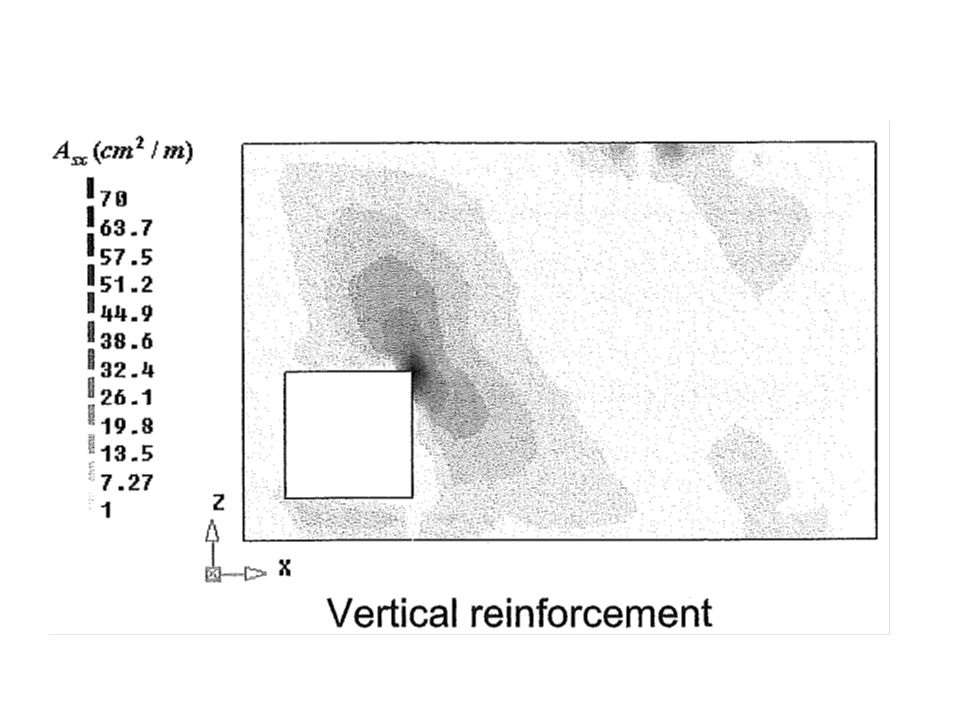
Reinforcement requirements (software)
")
11
Reinforcement (engineer)
")
12
Moments in concrete plates Only rebars in the x and y directions Equilibrium of a plate part Result (Yield contour)
")
14
Example 3 Moments in a point m xx = 13, m yy = -8, m xy = 5 kNm/m Moment capacities m px = 17, m py = 0, m’ px =0, m’ py = 10 Is the capacity sufficient? Yes

15
Design of moment reinforcement Carry the moments with the least amount of reinforcement. So, minimize m px + m py + m’ px + m’ py 5 constraints m px, m py, m’ px, m’ py ≥ 0 Solution 1 (Wood-Armer moments) Crack direction 45º to the reinforcing bars
 Crack direction 45º to the reinforcing bars.")
16
Solution 2 (when m px would be < 0) Solution 3 (when m py would be < 0)
 Solution 3 (when m py would be < 0)")
17
Solution 4 (when m’ px would be < 0) Solution 5 (when m’ py would be < 0)
 Solution 5 (when m’ py would be < 0)")
18
Solution 6 (when m px and m py would be < 0) Solution 7 (when m’ px and m’ py would be < 0)
 Solution 7 (when m’ px and m’ py would be < 0)")
19
Example 4 Moments in a point (as in example 1) m xx = 13, m yy = -8, m xy = 5 kNm/m Moment capacities m px = 13+5²/8 = 16.13m’ px = 0 m py = 0m’ py = 8+5²/13 = 9.92 Amount of reinforcement is proportional to 16.13+0+0+9.92 = 26 Amount of reinforcement in example 3 17+0+0+10 = 27 (larger, so not optimal)
 m xx = 13, m yy = -8, m xy = 5 kNm/m Moment capacities m px = 13+5²/8 = 16.13m’ px = 0 m py = 0m’ py = 8+5²/13 = 9.92 Amount of reinforcement is proportional to = 26 Amount of reinforcement in example = 27 (larger, so not optimal)")
20
Example 5 Plate bridge, simply supported 4 x 8 m, point load 80 kN, thick 0.25 m

21
Example 5 continued Decomposition of the load

22
Example 5 Torsion moment

23
Example 5 All moments Moments in the bridge middle Moments at the bridge support

24
Example 5 FEM moments

27
Example 5 Reinforcement Middle Support Designed

28
Example 5 Upper bound check Result > 1OK

29
Computed requirements

33
Conclusions The design procedure used is 1 Compute the force flow linear elastically 2 Choose the dimensions plastically The reason for the linear elastic analysis in the first step is that it shows us how an as yet imperfect design can be improved. A plastic (or nonlinear) analysis in step 1 would shows us how the structure would collapse; but that is not what we want to know in design. This procedure is applied to design many types of structure for the ULS.
 analysis in step 1 would shows us how the structure would collapse; but that is not what we want to know in design. This procedure is applied to design many types of structure for the ULS..")
Similar presentations


>")


