Download presentation
Presentation is loading. Please wait.

1
Module 3 Practical Tasks

2
Practical Task 1: Gravity feed magazine
Task description: Wooden planks are to be pushed along from a gravity feed magazine to a clamping device. By pressing a pushbutton valve one plank is pushed by the slide out of the gravity feed magazine. After the slide has reached the forward end position it returns to its start position.

3
Practical Task 1: Gravity feed magazines
Task requirements: 1. Draw pneumatic circuit diagram to control the movement of the slide. 2. Simulate the circuit using Fluid SIM software. 3. Assemble the circuit practically and check its operation. Draw the Pneumatic Circuit in the table provided in your module

5
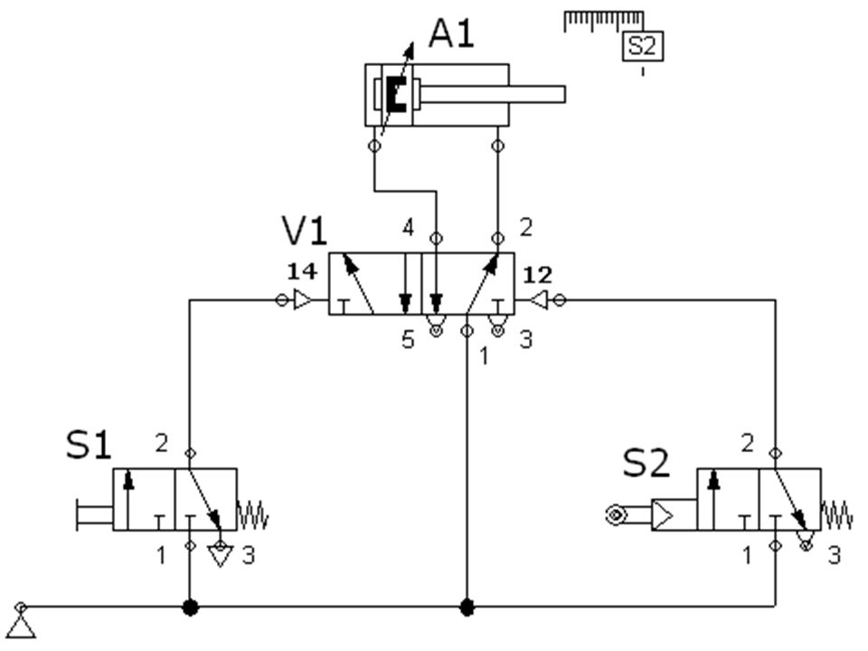
Solution Description All valves are un-actuated in the initial position, pressure is applied at the piston rod side of the cylinder and the piston rod remains in the retracted state. By pressing the push button valve S1, a signal is applied at the control port 14 of the double pilot valve V1. The valve V1 switches, and the pressure is applied at the piston side of the cylinder and the piston rod advances. When the piston rod reaches the end position, the cam of the cylinder will press the valve S2 (3/2 way, roller lever valve).A signal is now applied at the control port 12 of the valve V1. The valve V1 switches, and the pressure is applied at the piston rod side of the cylinder and the piston rod retracts.
.A signal is now applied at. the control port 12 of the valve V1. The valve V1 switches, and the. pressure is applied at the piston rod side of the cylinder and the piston. rod retracts.")
6
Practical Task 2 – Diverting Device
Task description: Using a diverting device, parts are to be moved from one conveyor track onto the other in a linear sequence. By operating a selector valve the oscillating piston rod of a cylinder pushes the turntable via a pawl in stepped sequence. The parts are diverted and transported onwards in the opposite direction. By returning the selector valve back to the normal position the drive unit is switched off.

7
Practical Task 2 – Diverting Device
Task requirements: 1. Draw a pneumatic circuit diagram to control the operation of the piston. 2. Simulate the circuit using FluidSIM software. 3. Assemble the circuit practically and check its operation. Draw the Pneumatic Circuit in the table provided in your module

9
Practical Task 2 – Diverting Device Solution Description
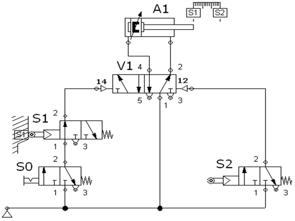
All valves are un-actuated in the initial position, pressure is applied at the piston rod side of the cylinder and the piston rod remains in the retracted state. By operating the selector valve S0, the pressure reaches the valve S1 and a signal is applied at the control port 14 of the double pilot valve V1. The valve V1 switches, and the pressure is applied at the piston side of the cylinder and the piston rod advances. When the piston rod reaches the end position, the cam of the cylinder will press the valve S2 (3/2 way, roller lever valve).A signal is now applied at the control port 12 of the valve V1. The valve V1 switches, and the pressure is applied at the piston rod side of the cylinder and the piston rod retracts. When the piston rod reaches the front position, the cam of the cylinder will press the valve S1 (3/2 way, roller lever valve).A signal is now applied at the control port 14 of the valve V1. The valve V1 switches, and the pressure is applied at the piston side of the cylinder and the piston rod advances again. Accordingly; an oscillating motion is created. By returning the valve S0 back to the normal position, the cylinder will stop oscillating.
.A signal is now applied at the control port 12 of the valve V1. The valve V1 switches, and the pressure is applied at the piston rod side of the cylinder and the piston rod retracts. When the piston rod reaches the front position, the cam of the cylinder will press the valve S1 (3/2 way, roller lever valve).A signal is now applied at the control port 14 of the valve V1. The valve V1 switches, and the pressure is applied at the piston side of the cylinder and the piston rod advances again. Accordingly; an oscillating motion is created. By returning the valve S0 back to the normal position, the cylinder will stop oscillating.")
10
Practical Task 3 – Clamping Device (indirect control)
Task description: A single-acting cylinder with a large piston diameter is to clamp a work piece following actuation of a push button. The cylinder is to retract once the push button is released. Positional sketch

11
Practical Task 3 – Clamping Device (indirect control)
Task requirements: 1. Draw a pneumatic circuit diagram to control the operation of the piston. 2. Simulate the circuit using FluidSIM software. 3. Assemble the circuit practically and check its operation. Draw the Pneumatic Circuit in the table provided in your module

13
Another Solution: If you do not have the valve 1V, you can use the 5/2 way single pilot valve, and close port 2 (practically, by using T junction and a short hose). Hint: A double acting cylinder could be used instead of the single acting cylinder and in this case port 2 in the DCV will be connected to the retract port of the double acting cylinder to operate the circuit.

14
Practical Task 3 – Clamping Device (indirect control)---Solution Description
In the initial position, the single-acting cylinder 1A is retracted. A spring return 3/2-way valve is used to actuate the cylinder. Connection 1 of the valve 1V is closed; connection 2 is exhausted to atmosphere via connection 3. The valve 1S is actuated when the push button is activated and pressure is applied to the control port 12 of the control valve 1V. The control valve 1V is actuated against spring force and is thus switched to flow. The pressure building up at the cylinder piston causes the cylinder piston rod of the single-acting cylinder to extend. The signal at the control port 12 remains as long as the push button is operated. Once the piston rod has reached end position, it returns only after the push button has been released. When the push button is released, the valve 1S returns to its initial position. Control port 12 of the control valve 1V exhausts to atmosphere and the signal is reset. The control valve also returns to initial position. The return spring causes the cylinder to retract. The air from the cylinder chamber is exhausted to atmosphere via the control valve.

Similar presentations