Download presentation
Presentation is loading. Please wait.

1
2. RESISTIVE CIRCUITS CIRCUITS by Ulaby & Maharbiz Piezoresistive sensor All rights reserved. Do not reproduce or distribute. ©2013 Technology and Science Press

2
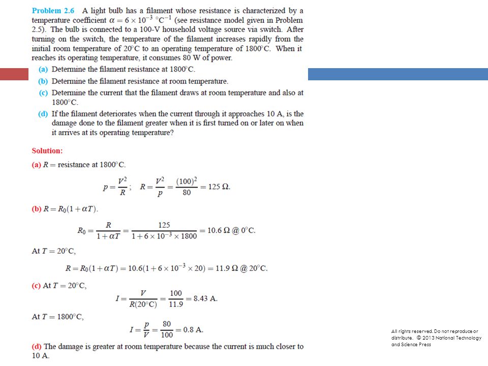
All rights reserved. Do not reproduce or distribute. © 2013 National Technology and Science Press

3
Ohm’s Law Voltage across resistor is proportional to current Resistance: ability to resist flow of electric current resistivity All rights reserved. Do not reproduce or distribute. © 2013 National Technology and Science Press

4
Conductivity All rights reserved. Do not reproduce or distribute. © 2013 National Technology and Science Press

5
Resistor Codes All rights reserved. Do not reproduce or distribute. © 2013 National Technology and Science Press

6
Example 2-1: dc Motor = 98% of P What fraction of power supplied by the battery is dissipated in the motor? Solution: All rights reserved. Do not reproduce or distribute. © 2013 National Technology and Science Press

8
Tech Brief 2: Superconductivity Critical temperature T C is the temperature at which a material becomes superconducting (zero resistance & no power dissipation) All rights reserved. Do not reproduce or distribute. © 2013 National Technology and Science Press

9
Kirchhoff’s Current Law Sum of currents entering a node is zero Also holds for closed boundary All rights reserved. Do not reproduce or distribute. © 2013 National Technology and Science Press

10
Example All rights reserved. Do not reproduce or distribute. © 2013 National Technology and Science Press

11
Kirchhoff’s Voltage Law (KVL) Sum of voltages around a closed path is zero Sum of voltage drops = sum of voltage rises All rights reserved. Do not reproduce or distribute. © 2013 National Technology and Science Press

12
Example : KCL/KVL Determine all currents & voltages Solution: Three equations w/three unknowns: Loop 1 Loop 2 All rights reserved. Do not reproduce or distribute. © 2013 National Technology and Science Press

13
All rights reserved. Do not reproduce or distribute. © 2013 National Technology and Science Press

14
Equivalent Circuits If the current and voltage characteristics at nodes are identical, the circuits are considered “equivalent” Identifying equivalent circuits simplifies analysis All rights reserved. Do not reproduce or distribute. © 2013 National Technology and Science Press

15
Resistors in Series Equivalent resistance (series) is sum of resistances Voltage divided over resistors (voltage divider) All rights reserved. Do not reproduce or distribute. © 2013 National Technology and Science Press

16
Adding Sources In Series Unrealizable Circuit Combining voltage sources All rights reserved. Do not reproduce or distribute. © 2013 National Technology and Science Press

17
Resistors in Parallel All rights reserved. Do not reproduce or distribute. © 2013 National Technology and Science Press

18
Source Transformation Hence, For the two circuits to be equivalent : All rights reserved. Do not reproduce or distribute. © 2013 National Technology and Science Press

19
Example 2-10: Source Transformation All rights reserved. Do not reproduce or distribute. © 2013 National Technology and Science Press

20
Circuit with no two resistors sharing the same current or same voltage R1,R2,R3=Delta R3,R4,R5=Delta R2,R3,R5=Y R1,R3,R4=Y All rights reserved. Do not reproduce or distribute. © 2013 National Technology and Science Press

21
( Assuming no connection at node 3) Hence, All rights reserved. Do not reproduce or distribute. © 2013 National Technology and Science Press

22
Simultaneous solution leads to: All rights reserved. Do not reproduce or distribute. © 2013 National Technology and Science Press

23
Example 2-12: Y- Δ Circuit All rights reserved. Do not reproduce or distribute. © 2013 National Technology and Science Press

24
All rights reserved. Do not reproduce or distribute. © 2013 National Technology and Science Press

25
Wheatstone Bridge Measurement instrument based on differential measurement Balanced Condition: Determine unknown resistance based on “balanced” condition For balanced condition All rights reserved. Do not reproduce or distribute. © 2013 National Technology and Science Press

26
Wheatstone Sensor Determine Vout All rights reserved. Do not reproduce or distribute. © 2013 National Technology and Science Press

27
Tech Brief 3: Resistors As Sensors Piezoresistive Sensors All rights reserved. Do not reproduce or distribute. © 2013 National Technology and Science Press

28
Tech Brief 3: Resistors As Sensors All rights reserved. Do not reproduce or distribute. © 2013 National Technology and Science Press

29
Tech Brief 3: Resistors As Sensors Thermistor Sensors All rights reserved. Do not reproduce or distribute. © 2013 National Technology and Science Press

30
Example 2-16: Piezoresistor Cantilever (400 times greater than w/o cantilever) All rights reserved. Do not reproduce or distribute. © 2013 National Technology and Science Press

31
Linear i-v relationships All rights reserved. Do not reproduce or distribute. © 2013 National Technology and Science Press

32
The Diode Current can flow only from + to – through a diode. All rights reserved. Do not reproduce or distribute. © 2013 National Technology and Science Press

33
All rights reserved. Do not reproduce or distribute. © 2013 National Technology and Science Press

34
Multisim SPICE simulator software Powerful tool for analyzing circuits See tutorial and examples on CD that accompanies the text All rights reserved. Do not reproduce or distribute. © 2013 National Technology and Science Press

35
Multisim: Creating a Circuit All rights reserved. Do not reproduce or distribute. © 2013 National Technology and Science Press

36
Multisim: DC Operating Point Solution All rights reserved. Do not reproduce or distribute. © 2013 National Technology and Science Press

37
Multisim Solution Window All rights reserved. Do not reproduce or distribute. © 2013 National Technology and Science Press

38
Summary All rights reserved. Do not reproduce or distribute. © 2013 National Technology and Science Press

Similar presentations


: Circuits I Spring 2014 1 April 8, 2014.>")


