Download presentation
Presentation is loading. Please wait.

1
Impedance Transformation

2
Topics Quality Factor Series to parallel conversion Low-pass RC High-pass RL Bandpass Loaded Q Impedance Transformation Coupled Resonant Circuit – Recent implementation, if time permits

3
Quality Factor

4
Q is dimensionless

5
Quality factor of an inductor (I max ) Q=(ωL)/R Please note that Q is also equal to Q=Im(Z)/Re(Z)
 Q=(ωL)/R Please note that Q is also equal to Q=Im(Z)/Re(Z)")
6
Quality factor of Parallel RL circuit Q=Im(Z)/Re(Z) Q=ωL(R p ) 2 /(ω 2 L 2 R p )=R p /ωL
/Re(Z) Q=ωL(R p ) 2 /(ω 2 L 2 R p )=R p /ωL")
7
Quality factor of a Capacitor Q=ωCR Please note that Q is also equal to Q=Im(Z)/Re(Z) Z is the impedance of parallel RC
/Re(Z) Z is the impedance of parallel RC")
8
Quality factor of a Capacitor in Series with a Resistor Q=1/(ωCR S ) Please note that Q is also equal to Q=Im(Z)/Re(Z) Z is the impedance of series RC
 Please note that Q is also equal to Q=Im(Z)/Re(Z) Z is the impedance of series RC")
9
Low-Pass RC Filter

10
High-Pass Filter

11
LPF+HPF

12
LPF+HPF (Magnified)
")
13
Resistor Removed

14
Design Intuition

15
Circuit Quality Factor Q=3.162/(5.129-1.95)=0.99
=0.99")
16
Mathematical Analysis

17
Transfer Function of a Bandpass Filter Resonant frequency

18
Cutoff Frequency

19
Bandwidth Calculation

20
Equivalent Circuit Approach At resonant frequency, XP=1/(ω o C p )
")
21
Effect of the Source Resistance Q=3.162/(0.664)=4.76
=4.76")
22
Effect of the Load Resistor 6 dB drop at resonance due to the resistive divider. Q=3.162/(7.762-1.318)=0.49 The loading will reduce the circuit Q.
=0.49 The loading will reduce the circuit Q..")
23
Summary Q=0.99 Q=4.79 Q=0.49

24
Design Constraints Specs – Resonant Frequency: 2.4 GHz – R S =50 Ohms – R L =Infinity List Q, C & L

25
Values QCL 0.50.663 pF6.63 nH 11.326 pF3.315 nH 1013.26 pF331.5 pH Specs: Resonant Frequency: 2.4 GHz R S =50 Ohms R L =Infinity

26
Design Example Q=2.4/(2.523-2.286)=10.12 BW=237 MHz
=10.12 BW=237 MHz")
27
Implement the Inductor

28
http://www-smirc.stanford.edu/spiralCalc.html

29
Resistance of Inductor R=R sh (L/W) – R sh is the sheet resistance – Rsh is 22 mOhms per square for W=6um. – If the outer diameter is 135 um, the length is approximately 135um x4=540 um. – R=22 mOhms x (540/6)=1.98 Ohms Q=(ωL)/R=(2π2.4G0.336 nH)/1.98 Ω=2.56
=1.98 Ohms Q=(ωL)/R=(2π2.4G0.336 nH)/1.98 Ω=2.56.")
30
Include Resistor In the Tank Circuitry Q=2.427/(3.076-1.888)=2.04 Inclusion of parasitic resistance reduces the circuit Q from 10.
=2.04 Inclusion of parasitic resistance reduces the circuit Q from 10.")
31
Series to Parallel Conversion

32
We have an open at DC! We have resistor R P at DC! It is NOT POSSIBLE to make these two circuits Identical at all frequencies, but we can make these to exhibit approximate behavior at certain frequencies.

33
Derivation Q S =Q P

34
RPRP Q S =1/(ωC S R S )
")
35
Cp Q S =1/(ωC S R S )
")
36
Summary

37
Series to Parallel Conversion for RL Circuits

38
Resistance of Inductor R=R sh (L/W) – R sh is the sheet resistance – Rsh is 22 mOhms per square for W=6um. – If the outer diameter is 135 um, the length is approximately 135um x4=540 um. – R=22 mOhms x (540/6)=1.98 Ohms Q=(ωL)/R=(2π2.4G0.336 nH)/1.98 Ω=2.56 R p =R S (1+Q S Q S )=1.98 Ohms(1+2.56x2.56)=14.96 Ohms L p =L S (1+1/(Q S Q S ))=331.5 pH(1+1/2.56/2.56)=382.08 nH
=1.98 Ohms Q=(ωL)/R=(2π2.4G0.336 nH)/1.98 Ω=2.56 R p =R S (1+Q S Q S )=1.98 Ohms(1+2.56x2.56)=14.96 Ohms L p =L S (1+1/(Q S Q S ))=331.5 pH(1+1/2.56/2.56)= nH.")
39
Insertion Loss Due to Inductor Resistance At resonant frequency, voltage divider ratio is 14.96Ω/(14.96 Ω+50 Ω)=0.2303 Convert to loss in dB, 20log 10 (0.23)=-12.75 dB
= Convert to loss in dB, 20log 10 (0.23)= dB")
40
Use Tapped-C Circuit to Fool the Tank into Thinking It Has High R S

41
Derivation

42
Previous Design Values QCL 0.50.663 pF6.63 nH 11.326 pF3.315 nH 1013.26 pF331.5 pH Specs: Resonant Frequency: 2.4 GHz R S =50 Ohms R L =Infinity

43
Design Problem Knowns & Unknowns Knowns: R S =50 Ohms CT=13.26 pF Unknowns: C 1 /C 2 R’ S

44
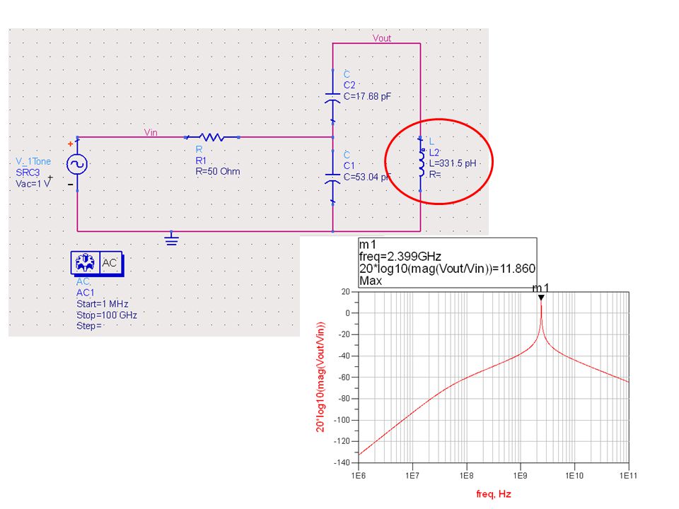
Calculations C T =C 1 /(1+C 1 /C 2 ) C 1 =C T (1+C 1 /C 2 ) C 1 /C 2 R’ S C1C1 C2C2 1200 Ω26.52 pF 2450Ω39.78 pF19.89 pF 3800Ω53.04 pF17.68 pF
 C 1 =C T (1+C 1 /C 2 ) C 1 /C 2 R’ S C1C1 C2C Ω26.52 pF 2450Ω39.78 pF19.89 pF 3800Ω53.04 pF17.68 pF")
46
Include the Effect of Parasitic Resistor

Similar presentations


. Outline Three Element Matching – Motivation – Pi Network – T Network Low Q or Wideband Matching Network Impedance Matching on.>")


 Jack Ou ES590. Outline Butterworth LPF Design Example LPF to HPF Conversion LPF to BPF Conversion LPF to BRF Conversion.>")

 to.>")


. Maximum Power Transfer Choose an RL in order to maximize power delivered to RL.>")


