Download presentation
Presentation is loading. Please wait.

1
Technical Training Program on IMPULSE AC Drives
Welcome to Magnetek Material Handling & Kor-Pak Corporation Welcome to Magnetek Material Handling’s Technical Training Program. This training program has been specifically designed to provide information regarding the application, use and troubleshooting of the IMPULSE G+ Mini and the IMPULSE G+/VG+ Series 4 AC drives. If you should have any questions during this three-day training session, please ask your instructor. Technical Training Program on IMPULSE AC Drives Chris Koralik Kor-Pak Corporation

2
Impulse Drives: Safety Features

4
Impulse Drives: Safety Features

6
Diagram of VFD Process

9
Impulse Drives: Safety Features

10
Impulse Drives: Safety Features

12
Impulse Drives: Safety Features

14
Diagram of VFD Process

17
IMPULSE® Drives Section B will include
Terms associated with IMPULSE drives in overhead crane applications Basic theory of IMPULSE AC Adjustable Frequency Drives Programming of IMPULSE®G+ Mini and IMPULSE®G+/VG+ Series 4 drives Trouble shooting of IMPULSE®G+ Mini and IMPULSE®G+/VG+ Series 4 drives Material to be covered in section B

18
IMPULSE Drives Application Questionnaire Hoist Manufacturer Motor Data
Special Motor Type Brake Type Facility Data New or Existing Application Equipment Data Other Options Required An application “Questionnaire” is useful for both determining requirements for a new application as well as troubleshooting. For new applications, use of this questionnaire guarantees the proper drive is chosen for the specific application. For troubleshooting, it helps one to determine the application the drive is being used in.

19
IMPULSE Drives CMAA Crane Classification
Class A – Standby/Infrequent Service Class B – Light Service Class C – Moderate Service CMAA Crane Classification Definitions Class A (Standby or Infrequent Service) This service class covers cranes which may be used in installations such as powerhouses, public utilities, turbine rooms, motor rooms, and transformer stations where precise handling of equipment at slow speeds with long, idle periods between lifts are required. Capacity loads may be handled for initial installation of equipment and for infrequent maintenance. Class B (Light Service) This service covers cranes which may be used in repair shops, light assembly operations, service buildings, light warehousing, etc., where service requirements are light and the speed is slow. Loads may vary from no load to occasional full rated loads with two to five lifts per hour, averaging ten feet per lift. Class C (Moderate Service) This service covers cranes which may be used in machine shops or paper mill machine rooms, etc., where service requirements are moderate. In this type of service the crane will handle loads which average 50 percent of the rated capacity with five to 10 lifts per hour, but not over 50 percent of the lifts at rated capacity.
 This service class covers cranes which may be used in installations such as powerhouses, public utilities, turbine rooms, motor rooms, and transformer stations where precise handling of equipment at slow speeds with long, idle periods between lifts are required. Capacity loads may be handled for initial installation of equipment and for infrequent maintenance. Class B (Light Service) This service covers cranes which may be used in repair shops, light assembly operations, service buildings, light warehousing, etc., where service requirements are light and the speed is slow. Loads may vary from no load to occasional full rated loads with two to five lifts per hour, averaging ten feet per lift. Class C (Moderate Service) This service covers cranes which may be used in machine shops or paper mill machine rooms, etc., where service requirements are moderate. In this type of service the crane will handle loads which average 50 percent of the rated capacity with five to 10 lifts per hour, but not over 50 percent of the lifts at rated capacity.")
20
IMPULSE Drives CMAA Crane Classification Class D – Heavy Service
Class E – Severe Service Class F – Continuous Severe Duty CMAA Crane Classification Definitions (continued) Class D (Heavy Service) This service covers cranes which may be used in heavy machine shops, foundries, fabricating plants, steel warehouses, container yards, lumber mills, etc.; standard duty bucket and magnet operations where heavy duty production is required. In this type of service, loads approaching 50 percent of the rated capacity will be handled constantly during the working period. High speeds are desirable for this type of service with 10 to 20 lifts per hour averaging 15 feet, but not over 65 percent of the lifts at rated capacity. Class E (Severe Service) This type of service requires a crane capable of handling loads approaching a rated capacity throughout its life. Applications may include magnet, bucket, magnet/bucket combination cranes for scrap yards, cement mills, lumber mills, fertilizer plants, container handling, etc. with twenty or more lifts per hour at or near the rated capacity. Class F (Continuous Severe Service) This type of service requires a crane capable of handling loads approaching rated capacity continuously under severe service conditions throughout its life. Applications may include custom designed specialty cranes essential to performing the critical work tasks affecting the total production facility. These cranes must provide the highest reliability with special attention to ease of maintenance features.
 Class D (Heavy Service) This service covers cranes which may be used in heavy machine shops, foundries, fabricating plants, steel warehouses, container yards, lumber mills, etc.; standard duty bucket and magnet operations where heavy duty production is required. In this type of service, loads approaching 50 percent of the rated capacity will be handled constantly during the working period. High speeds are desirable for this type of service with 10 to 20 lifts per hour averaging 15 feet, but not over 65 percent of the lifts at rated capacity. Class E (Severe Service) This type of service requires a crane capable of handling loads approaching a rated capacity throughout its life. Applications may include magnet, bucket, magnet/bucket combination cranes for scrap yards, cement mills, lumber mills, fertilizer plants, container handling, etc. with twenty or more lifts per hour at or near the rated capacity. Class F (Continuous Severe Service) This type of service requires a crane capable of handling loads approaching rated capacity continuously under severe service conditions throughout its life. Applications may include custom designed specialty cranes essential to performing the critical work tasks affecting the total production facility. These cranes must provide the highest reliability with special attention to ease of maintenance features.")
21
CMAA Crane Classifications Class A and B
IMPULSE Drives CMAA Crane Classifications Class A and B Class A (standby or Infrequent Ser Definition of CMAA class C application Magnetek will supply class ”C” dynamic braking circuitry in most CMAA class A and B applications NOTE – exception is taken to class C dynamic braking circuitry for No Load Brake Hoist motions in power house, turbine maintenance types of applications. A unique sizing of dynamic braking circuitry is required, the dynamic braking circuitry will be sized based on motor design and Full Load Amperage as well as length of travel and hoist speed

22
CMAA Crane Classifications Class C
IMPULSE Drives CMAA Crane Classifications Class C Definition of CMAA class C application Magnetek will supply class ”C” dynamic braking circuitry in these applications

23
CMAA Crane Classifications Class D
IMPULSE Drives CMAA Crane Classifications Class D Definition of CMAA class D application Hoists in class D applications may or may not have a Mechanical Load Brake Magnetek will furnish class “D” rated dynamic braking circuitry for traverse motions and No Load Brake hoist motions, but for Mechanical Load Brake motions class “C” traverse motion dynamic braking circuitry is used

24
CMAA Crane Classifications Class E
IMPULSE Drives CMAA Crane Classifications Class E Definition of CMAA class E application It is typical that all hoists in class E applications are a No Load Brake design. Magnetek will furnish class “E” rated dynamic braking circuitry

25
CMAA Crane Classifications Class F
IMPULSE Drives CMAA Crane Classifications Class F Definition of CMAA class F application It is typical that all hoists in class F applications are a No Load Brake design. Magnetek will furnish class “F” rated dynamic braking circuitry

26
IMPULSE Drives HMI Classification H1 – Infrequent Service or Standby
H2 – Light H3 – Standard H4 – Heavy H5 - Severe HMI – Hoist Duty Service Classification H1 – Infrequent or Standby Powerhouse and utilities, infrequent handling. Hoists used primarily to install and service heavy equipment where loads frequently approach hoist capacity with periods of utilization being infrequent and widely scattered. H2 – Light Light machine shop, fabricating industries, service and maintenance work where loads and utilization are randomly distributed with capacity loads infrequently handled, and where total running time of equipment does not exceed 10-15% of the work period. H3 – Standard General machine shop, fabricating, assembly, storage and warehousing where loads and utilization are randomly distributed with total running time of equipment not exceeding 15-25% of the work period.

27
Mechanical Load Brake Hoists
IMPULSE Drives Mechanical Load Brake Hoists Simplified representation of a mechanical load brake hoist

28
IMPULSE Drives Mechanical Load Brake Hoists
Defined by CMAA as a hoist control braking means Controls load during lowering Keeps load from falling if motor brake fails Supplements the electric motor brake Mechanical Load Brake Hoists Function The mechanical load brake is defined by CMAA as a hoist control braking means. It is an integral part of the hoist gear train. Its purpose is to control the load during lowering and to keep the load from falling if the motor brake fails. The mechanical load brake supplements the electric motor brake. A typical ratchet and pawl type mechanical load brake is shown on the previous page. Note that the ratchet wheel has two friction faces. It is free to rotate on the hub of the motor gear, but can rotate only in the up direction since the ratcheted pawl locks it to prevent rotation in the down direction. The motor gear is not keyed to the disc plate shaft, but transmits its torque through the acme thread on the shaft. Action of the screw thread causes an axial movement of the motor gear which engages and disengages the friction surfaces on the ratchet wheel, depending on the relative speed and direction of the rotation of the motor gear and disc shaft. Some mechanical load brake designs make use of over-running clutches in lieu of ratchets and pawls, but regardless of which type of mechanism is used, the function is the same. In operation, the mechanical load brake serves a dual function. It acts as a brake in slowing or stopping a load. But during the lowering operation, it also serves as a clutch by providing control over the rate of load descent.

29
IMPULSE Drives Mechanical Load Brake Hoists Applying IMPULSE Drives
Use the standard hoist amp-acity rating when selecting a drive Due to wear of the mechanical load brake, hoists require dynamic braking resistors Mechanical Load Brake Hoists Applying IMPULSE Drives 1. When selecting a drive, use the standard hoist amp-acity rating (constant torque rating). Drives need not be oversized for class of service. 2. Most hoists with mechanical load brakes do require dynamic braking resistors. Experience has shown that all hoists eventually, due to wear of the mechanical load brake, require dynamic braking resistors. They are sized for approximately 50% braking torque. Because of the wear and lack of maintenance associated with mechanical load brakes under heavy duty service, some load brakes will slip in time causing a loss in operating performance. In these instances, adding dynamic braking resistors serve as a wear indicator in that when OV faults occur, the mechanical load brake is not functioning properly and needs maintenance. Some new hoists may also require dynamic braking resistors to avoid nuisance OV trips caused by minor slippage in the mechanical load brake when changes in speed or load occur. Speeds below 6Hz will not be possible.
. Drives need not be oversized for class of service. 2. Most hoists with mechanical load brakes do require dynamic braking resistors. Experience has shown that all hoists eventually, due to wear of the mechanical load brake, require dynamic braking resistors. They are sized for approximately 50% braking torque. Because of the wear and lack of maintenance associated with mechanical load brakes under heavy duty service, some load brakes will slip in time causing a loss in operating performance. In these instances, adding dynamic braking resistors serve as a wear indicator in that when OV faults occur, the mechanical load brake is not functioning properly and needs maintenance. Some new hoists may also require dynamic braking resistors to avoid nuisance OV trips caused by minor slippage in the mechanical load brake when changes in speed or load occur. Speeds below 6Hz will not be possible.")
30
IMPULSE Drives Worm Gear Hoists Worm Gear hoist

31
IMPULSE Drive Worm Gear Hoists
Considered by CMAA to be equipped with a controlled braking means Common misconception that all worm gears are self- locking or non-overhauling Worm Gear Hoists Function Worm gear hoists, the angle of whose worm is such as to prevent the load from accelerating in the lowering direction, are considered by CMAA to be equipped with a controlled braking means. It is a common misconception that all worm gears are self-locking or non-overhauling. Actually, worm gear ratios up to 15:1 will overhaul quite freely. Ratios from 20:1 to 40:1 can generally be considered self-locking, but these may or may not overhaul depending on loading, lubrication and the amount of vibration present. Self-locking ratios (generally 40:1 and higher) are susceptible to the phenomenon of stair-stepping when overhauling. Stair-stepping, an erratic rotation of the gear set, occasionally occurs when the gear set is back-driven at worm speeds less than the theoretical lock-up speed of the gear set. This condition can occur on hoists where there is a high inertial load at the output shaft.
 are susceptible to the phenomenon of stair-stepping when overhauling. Stair-stepping, an erratic rotation of the gear set, occasionally occurs when the gear set is back-driven at worm speeds less than the theoretical lock-up speed of the gear set. This condition can occur on hoists where there is a high inertial load at the output shaft.")
32
IMPULSE Drives Worm Gear Hoists Applying IMPULSE drives
Dynamic braking resistors should be used on all worm gear hoists Extremely slow speeds may not be achievable Program IMPULSEG+ Series 4 and IMPULSEG+ Mini to overcome lockup at start (voltage boost) Worm Gear Hoists Applying IMPULSE Drives 1. Dynamic braking resistors should be used on all worm gear hoists. 2. Because of the tendency for some worm gears to stair-step at very slow speeds, extremely slow speeds (< 6.0 Hz for NEMA B, or < 10 Hz for NEMA D) may not be achievable. 3. Program IMPULSE drive to provide a momentary current boost at “Start” to provide sufficient torque to overcome lockup.
 Worm Gear Hoists. Applying IMPULSE Drives. 1. Dynamic braking resistors should be used on all worm gear hoists. 2. Because of the tendency for some worm gears to stair-step at very slow speeds, extremely slow speeds (< 6.0 Hz for NEMA B, or < 10 Hz for NEMA D) may not be achievable. 3. Program IMPULSE drive to provide a momentary current boost at Start to provide sufficient torque to overcome lockup.")
33
IMPULSE Drives Special Input Power Supplies
575 Volt AC (G+/VG+ Series 4) 250 Volt DC Single-Phase 25 Hertz Special Input Power Supplies Most industrial facilities will have either 230 or 460 VAC, three-phase and 50 or 60 Hz input power on their mainline runway conductors. The following unusual voltages are sometimes encountered: 575 Volt AC 575 VAC is common in Canada as well as textile mills in southeastern United States and other locations in the northeastern United States along the Canadian border. 250 Volt DC DC voltages of 250 VDC can be used as a supply for 200V series IMPULSE drives. The input voltage must be a minimum of 250 VDC and must be regulated. However, the output voltage from the drive to the motor will only be about 176 VAC. To obtain full torque at 100% speed, a special motor will be required. On traverse applications, a standard 208 VAC motor will typically be suitable.
 250 Volt DC. Single-Phase. 25 Hertz. Special Input Power Supplies. Most industrial facilities will have either 230 or 460 VAC, three-phase and 50 or 60 Hz input power on their mainline runway conductors. The following unusual voltages are sometimes encountered: 575 Volt AC 575 VAC is common in Canada as well as textile mills in southeastern United States and other locations in the northeastern United States along the Canadian border. 250 Volt DC DC voltages of 250 VDC can be used as a supply for 200V series IMPULSE drives. The input voltage must be a minimum of 250 VDC and must be regulated. However, the output voltage from the drive to the motor will only be about 176 VAC. To obtain full torque at 100% speed, a special motor will be required. On traverse applications, a standard 208 VAC motor will typically be suitable.")
34
IMPULSE Drives Recommended Motor Features Standard Duty
Squirrel Cage Motor NEMA Design B (3 to 5% Slip) TENV Enclosure Design 60-Minute Time Rating Class F Insulation Thermostats (Klixons in Stator Windings) Recommended New Motor Characteristics for Standard Duty Crane/Hoist Applications 1. Squirrel Cage Motor 2. NEMA Design B (3 to 5% Slip) 3. TENV Enclosure Design 4. 60-Minute Time Rating 5. Class F Insulation 6. Thermostats (Klixons in Stator Windings)
 TENV Enclosure Design. 60-Minute Time Rating. Class F Insulation. Thermostats (Klixons in Stator Windings) Recommended New Motor Characteristics for Standard Duty Crane/Hoist Applications. 1. Squirrel Cage Motor. 2. NEMA Design B (3 to 5% Slip) 3. TENV Enclosure Design Minute Time Rating. 5. Class F Insulation. 6. Thermostats (Klixons in Stator Windings)")
35
IMPULSE Drives Recommended Motor Features
Standard Duty – CMAA C and D applications Squirrel Cage Motor NEMA Design B (3 to 5% Slip) TENV Enclosure Design 60-Minute Time Rating Class F Insulation Thermostats (Klixons in Stator Windings) Recommended New Motor Characteristics for Standard Duty Crane/Hoist Applications 1. Squirrel Cage Motor 2. NEMA Design B (3 to 5% Slip) 3. TENV Enclosure Design 4. 60-Minute Time Rating 5. Class F Insulation 6. Thermostats (Klixons in Stator Windings)
 TENV Enclosure Design. 60-Minute Time Rating. Class F Insulation. Thermostats (Klixons in Stator Windings) Recommended New Motor Characteristics for Standard Duty Crane/Hoist Applications. 1. Squirrel Cage Motor. 2. NEMA Design B (3 to 5% Slip) 3. TENV Enclosure Design Minute Time Rating. 5. Class F Insulation. 6. Thermostats (Klixons in Stator Windings)")
36
IMPULSE Drives Recommended Motor Features
Special Duty CMAA class C, D and E applications All standard duty features 1.0 Service Factor on AFD Power Temperature rise over ambient rating of class F (115° C) Inverter Duty Motor Characteristics for Special Duty Crane/Hoist Applications 1. Standard Duty Recommendations Service Factor on AFD Power, 1.15 Service Factor on Sine Wave Power 3. Temperature Rise over Ambient Rating of Class F (115º)
 Inverter Duty Motor Characteristics for Special Duty Crane/Hoist Applications. 1. Standard Duty Recommendations Service Factor on AFD Power, 1.15 Service Factor on Sine Wave Power. 3. Temperature Rise over Ambient Rating of Class F (115º)")
37
IMPULSE Drives Applications Requiring Inverter Duty Motors
Special Duty CMAA class E and F applications Low speed (3 to 6 hz) operation for extended periods of time Very low speed (1.5 hz) operation w/100% motor torque, smooth shaft rotation CMAA class E or F cranes High ambient temperature environments Applications Which Would Involve or Require Inverter Duty Motors 1. Low Speed (3 to 6 Hz) Operation for Extended Periods of Time 2. Very Low Speed Operation (1.5 Hz) with 100% Motor Torque and Smooth Shaft Rotation 3. CMAA Class E or F Cranes 4. High Ambient Temperature Environments
 operation for extended periods of time. Very low speed (1.5 hz) operation w/100% motor torque, smooth shaft rotation. CMAA class E or F cranes. High ambient temperature environments. Applications Which Would Involve or Require Inverter Duty Motors. 1. Low Speed (3 to 6 Hz) Operation for Extended Periods of Time. 2. Very Low Speed Operation (1.5 Hz) with 100% Motor Torque and Smooth Shaft Rotation. 3. CMAA Class E or F Cranes. 4. High Ambient Temperature Environments.")
38
IMPULSE Drives Applications that may require “severe duty treatment”
TEBC construction or upsize frame Class H insulation Special pain coatings and shaft seals Severe Duty Applications May Require 1. TEBC construction or upsize of motor frame 2. Class H Insulation mandatory 3. Special paint / coatings and shaft seals (bearing isolators)
")
39
Applying NEMA D Motors IMPULSE Drives NEMA D Motors
NEMA Design D motors were commonly used in the past and can be found today on hoist motions with reversing contactor controls because of their high starting torque (up to 325% motor rated torque = 325% motor nameplate FLA). NEMA D motors also have a high slip (5 to 13%) which results in a lower speed ratio. A high starting torque is not required nor used on inverter controls because the drive varies the voltage and frequency to give a soft-start even on hoist applications. IMPULSE•G+ Series 4 can be used with NEMA D motors for hoist applications with mechanical load brakes or worm gear boxes. IMPULSE•VG+ Series 4 can also be used for hoists without mechanical load brakes. NEMA Design D motors with slips greater than 8% may be used with IMPULSE•G+ Series 4, but may be compatible with IMPULSE•VG+ Series 4. However, some speed regulation capability will be lost. Individual selected speeds will vary somewhat between a light load and a full capacity load. The speed regulation capabilities of IMPULSE•G+ Mini when used with NEMA D motors, may be only between 12:1 and 6:1 depending upon the amount of slip and nature of the hoist gear train. The negative effects of using a high slip motor can be reduced somewhat by using the Slip Compensation feature of IMPULSE drives.
. NEMA D motors also have a high slip (5 to 13%) which results in a lower speed ratio. A high starting torque is not required nor used on inverter controls because the drive varies the voltage and frequency to give a soft-start even on hoist applications. IMPULSE•G+ Series 4 can be used with NEMA D motors for hoist applications with mechanical load brakes or worm gear boxes. IMPULSE•VG+ Series 4 can also be used for hoists without mechanical load brakes. NEMA Design D motors with slips greater than 8% may be used with IMPULSE•G+ Series 4, but may be compatible with IMPULSE•VG+ Series 4. However, some speed regulation capability will be lost. Individual selected speeds will vary somewhat between a light load and a full capacity load. The speed regulation capabilities of IMPULSE•G+ Mini when used with NEMA D motors, may be only between 12:1 and 6:1 depending upon the amount of slip and nature of the hoist gear train. The negative effects of using a high slip motor can be reduced somewhat by using the Slip Compensation feature of IMPULSE drives.")
40
Applying Wound Rotor Motor
IMPULSE Drives Applying Wound Rotor Motor Wound Rotor Motors Wound rotor motors had been common place in the crane and hoist industry. When their secondary winding slip rings are shorted, their speed/torque curve is very similar to that of a NEMA Design A motor with very little slip. Consequently, they are ideal for adjustable frequency drives. Shorting the primary windings of a wound rotor motor characteristically results in the modified wound rotor motor having a lower impedance than a typical inverter duty motor. Placing a “load” reactor of 3% impedance between the output of an IMPULSE drive and converted wound rotor motor should result in an impendance that closely matches an inverter duty motor. When shorting the secondary winding of a wound rotor motor, we recommend brazing copper bars across all three rings adjacent to the wire leads. If the rotor has multiple sets of leads going to the slip rings, use multiple bars of copper equally spaced around the rings.

41
IMPULSE Drives Applying IMPULSE Drives to Existing Motors
Two-Speed/Two-Winding Consequent Pole Motors Single-Phase Motors Applying IMPULSE Drives for Use with Existing Motors Two-speed, two-winding squirrel cage motors are commonly used on hoists, trolleys and bridges for two-step speed regulation. IMPULSE drives can be wired to either the low-speed winding or high-speed winding and still provide greatly enhanced speed regulation and smooth control. Beware of the higher amperages associated with two-speed/two-winding motors when sizing IMPULSE drives. The low-speed motor windings are normally rated for 15 minute duty. In addition, because of the poor power factor characteristics associated with two-speed/two-winding motors (especially in the low-speed windings), the available speed range will only be in the area of between 6:1 and 10:1 depending upon the nature of the motor and gear train. Consequent pole multi-speed (multi-pole) motors are sometimes used on crane applications. The motor design and the contactor control scheme are more complicated than standard multi-winding motors. In this case, the low-speed wires (T1, T2 and T3) must be shorted together and the IMPULSE drive wired into the high-speed wires (T4, T5 and T6). Single-phase motors cannot be operated by an IMPULSE drive. If the motor uses a capacitor for starting, the capacitor will probably be damaged due to the high harmonic current flow. Single-phase motors typically use a separate start-and-run winding. When the motor reaches a preset speed, a centrifugal switch opens and de-energizes the start winding. Because of the slow, smooth starting of an IMPULSE drive, the switch will not open and the start-winding may burn out.
, the available speed range will only be in the area of between 6:1 and 10:1 depending upon the nature of the motor and gear train. Consequent pole multi-speed (multi-pole) motors are sometimes used on crane applications. The motor design and the contactor control scheme are more complicated than standard multi-winding motors. In this case, the low-speed wires (T1, T2 and T3) must be shorted together and the IMPULSE drive wired into the high-speed wires (T4, T5 and T6). Single-phase motors cannot be operated by an IMPULSE drive. If the motor uses a capacitor for starting, the capacitor will probably be damaged due to the high harmonic current flow. Single-phase motors typically use a separate start-and-run winding. When the motor reaches a preset speed, a centrifugal switch opens and de-energizes the start winding. Because of the slow, smooth starting of an IMPULSE drive, the switch will not open and the start-winding may burn out.")
42
IMPULSE Drives Selecting Line/Load Reactors Line reactors
Acts as a current limiting device Filters the waveform and attenuates electrical noise associated with AFD output Use continuous output rating of the drive when selecting line reactors Selecting Line/Load Reactors Three-phase line reactors offer an economical solution to a variety of application problems associated with adjustable frequency drives. Reactors can be used to solve problems on either the input or the output side of the drive. The line/load reactors supplied by Electromotive Systems have been selected specifically for use with AFDs. They have a 3% impedance rating. Line Reactors The line reactor acts as a current limiting device, filters the waveform and attenuates electrical noise associated with the AFD output. In this respect, the line reactor even surpasses the isolation transformer. On the line side of the AFD, reactors serve a bi-directional function. The properly applied impedance reactor minimizes nuisance tripping of drives caused by voltage spikes. Also, the reactor can protect from line sags because it performs a line stabilizing function. Looking on the line side from the opposite direction, the reactor filters out both pulsed and notched distortion. This minimizes interference with other sensitive electronic equipment, such as other AFDs, Material Handling, PLCs, telecommunications systems, etc. When selecting line reactors, use the continuous output ampere rating of the drive.

43
IMPULSE Drives Selecting Line/Load Reactors Load reactors
Used on the load side of the AFD between AFD and motor Protects the drive under motor short circuit conditions Reactor attempts to recreate perfect sine wave, improves motor efficiency Use the full load ampere rating of the motor when selecting load reactors Load Reactors The load reactor is used on the load side of the AFD between the AFD and the motor. It functions as a current limiting device to provide protection for the drive under motor short-circuit conditions. In this respect, the load reactor slows the rate of rise of the short-circuit current and limits the current to a safe value. By slowing the rate of current rise, the reactor allows ample time for the drive’s own protective circuits to react to the short circuit and trip out safely. Also, the reactor absorbs surges created by the motor load that might otherwise cause nuisance tripping of the drive. The reactor attempts to recreate a perfect sine wave, thus improving motor efficiency. When selecting load reactors, use the full load ampere rating of the motor. Load reactors need to be applied when using a wound rotor motor.

44
Input to Single AFD IMPULSE Drives Input to Single AFD
On the input side of an IMPULSE AFD, line reactors protect sensitive electronic equipment from electrical noise created by the drive (notching, pulsed distortion, harmonics, etc.). They also protect the AFD from surges or spikes on the incoming power lines, as well as reduce harmonic distortion.
. They also protect the AFD from surges or spikes on the incoming power lines, as well as reduce harmonic distortion.")
45
Input to Multiple AFDs IMPULSE Drives Input to Multiple AFDs
In certain applications, a single reactor may be used to serve multiple adjustable frequency drives provided drives are of exact same type on same motion. But the preferred method is to use a single reactor per drive.

46
IMPULSE Drives IMPULSE Controls Advantages
Variable speed control w/single-speed motor Minimizes high-starting current w/motor Adjust acceleration/deceleration rates Unique torque limit function Creep speed for precise positioning without plugging Can produce 150% full load torque IMPULSE Controls ~ Advantages Infinitely variable speed control can be accomplished using a standard, low-cost, single-speed AC squirrel cage induction motor in place of more expensive multi-speed or wound rotor motors. IMPULSE crane controls minimize the typically high starting in-rush current and drastically decreases the shock effect on both the load and the equipment. This ensures a smooth movement of the load and extends equipment life. Independently adjustable acceleration and deceleration rates and a unique torque limit function IMPULSE•G+ Mini and IMPULSE•G+ Series 4 in open loop vector mode and IMPULSE•VG+ Series 4 provide a cushioned, soft-start and stop. This guarantees controlled, accurate load movements and eliminates the need to jog or reverse plug the motor. Delicate loads can be positioned with precision creep speeds without the need for costly micro-speed motors or plugging motor controls. With IMPULSE crane controls, AC motors can produce up to 150% full load torque at all motor speeds.

47
IMPULSE Drives IMPULSE Controls Advantages
Inverter output frequencies > 60hz are possible Retrofit existing AC equipment IMPULSE Controls ~ Advantages Inverter output frequencies greater than 60 Hertz are possible when over-speeding of the motor is applicable. IMPULSE controls can be retrofitted to existing AC equipment. Single-speed, two-speed or wound rotor motors can easily be converted into high performance, variable speed motors.

48
IMPULSE Drives IMPULSE Controls Advantages
Lowers operating costs and minimizes equipment downtime AC squirrel cage induction motors for variable speed control provide reliability Electronic reversing, multi-speed operation eliminates conventional magnetic contactors Electronic dynamic braking provides effective braking without the use of mechanical brakes IMPULSE Controls Advantages IMPULSE controls lower operating costs and minimize equipment downtime. AC squirrel cage induction motors for variable speed control provide rugged, reliable, practically maintenance-free operation. Electronic reversing and multi-speed operation eliminate conventional magnetic contactors and their frequent maintenance. Electronic dynamic braking provides effective braking of the load without the use of mechanical brakes. This eliminates repetitive adjustments and dramatically reduces brake wear. This electro/mechanical brake acts only as a parking brake, setting after the motion has come to rest (for traverse motions).
.")
49
PWM Inverter IMPULSE Drives
Simplified diagram of IMPULSE drive power section.

50
PWM Inverter IMPULSE Drives
Actual diagram of early version “S” Series drive platform.

51
IMPULSE Drives PWM Waveforms

52
3Ø AC Motors IMPULSE Drives
Basic design of squirrel cage induction motor

53
V/F Ratio IMPULSE Drives
Maintaining the ratio of 460V / 60 Hz provides resulting current needed to produce motor rated torque at various output frequencies

54
Theoretical V/F Ratio w/Voltage Boost
IMPULSE Drives Theoretical V/F Ratio w/Voltage Boost Diagram represents the “theoretical” voltage boost at low output frequencies

55
V/F Curve IMPULSE Drives
Diagram represents the “speed / torque” of a motor through the available motor speed range when using an IMPULSE drive NOTE - diagram shows speed/torque for the V/F control mode with the published “40:1 Output Speed Control Range” for IMPULSE G+ Mini and G+ Series 4 drives

56
Torque & Horsepower vs. Speed
IMPULSE Drives Torque & Horsepower vs. Speed It is important to note that motor torque decreases exponentially when motor shaft speed exceeds motor rated synchronous speed

57
IMPULSE Drives IMPULSE Drive Characteristics Multi-Step
Infinitely Variable (2-Step Type) Speed Control Method Definitions Multi-Step Speed Control Method IMPULSE drives allow the user to select up to five speed points, the frequency (speed) of each point being selectable from a menu of five digital (preset) speeds. Infinitely Variable Speed Control Method (2-Step Type) IMPULSE drives can provide a true infinitely variable speed control with just two 120VAC inputs per motion direction. This method provides any speed between a programmed minimum and maximum motor speed by using a two detent pushbutton station or a remote crane control with levers/pushbuttons that have two detent positions. Pressing the button/lever to the first detent, the motor ramps up to a programmed minimum speed (typically 6Hz). Pressing the button/lever to the second detent, the motor will accelerate beyond the minimum programmed speed and up to a maximum speed (typically 60Hz). However, if there is a desired speed in between the minimum speed and maximum speed, the operator returns back to the first detent to hold the desired speed. To decelerate or stop, the operator releases the button/lever completely to its “off” position.
 Speed Control Method Definitions. Multi-Step Speed Control Method IMPULSE drives allow the user to select up to five speed points, the frequency (speed) of each point being selectable from a menu of five digital (preset) speeds. Infinitely Variable Speed Control Method (2-Step Type) IMPULSE drives can provide a true infinitely variable speed control with just two 120VAC inputs per motion direction. This method provides any speed between a programmed minimum and maximum motor speed by using a two detent pushbutton station or a remote crane control with levers/pushbuttons that have two detent positions. Pressing the button/lever to the first detent, the motor ramps up to a programmed minimum speed (typically 6Hz). Pressing the button/lever to the second detent, the motor will accelerate beyond the minimum programmed speed and up to a maximum speed (typically 60Hz). However, if there is a desired speed in between the minimum speed and maximum speed, the operator returns back to the first detent to hold the desired speed. To decelerate or stop, the operator releases the button/lever completely to its off position.")
58
IMPULSE Drives IMPULSE Drive Characteristics
Infinitely Variable (3-Step Type) Analog Speed Reference Via PC or PLC for Automation Speed Control Method Definitions (Continued) Infinitely Variable Speed Control Method (3-Step Type) IMPULSE drives provide true infinitely variable speed control with three simple 120V AC inputs. This method provides any speed between a programmed minimum and maximum motor speed by using a three detent pushbutton station or a remote crane control with levers/pushbuttons that have three detent positions. Pressing the button/lever to the first detent, the motor ramps up to a programmed minimum speed (typically 6Hz). Pressing the button/lever to the third detent, the motor will accelerate beyond the minimum programmed speed and up to the maximum speed. However, if there is a desired speed in between the minimum speed and maximum speed, the operator returns to the second detent to hold the desired speed. To decelerate, the operator returns to the first detent position or releases the button/lever to the “off” position. Analog Speed Reference IMPULSE will accept a 0-10V DC or 4-20mA analog input for variable speed control from analog output controllers such as joysticks and various radio controls. The IMPULSE G+ and VG+ Series 4 drives will also accept a -10 to +10V DC analog (bi-polar) input as well. Via PC or PLC for Automation IMPULSE can also be controlled by digital or analog outputs from PC’s and PLC’s. Special interface cards can be provided to handle digital input voltages other than the standard 120V AC.
 Analog Speed Reference. Via PC or PLC for Automation. Speed Control Method Definitions (Continued) Infinitely Variable Speed Control Method (3-Step Type) IMPULSE drives provide true infinitely variable speed control with three simple 120V AC inputs. This method provides any speed between a programmed minimum and maximum motor speed by using a three detent pushbutton station or a remote crane control with levers/pushbuttons that have three detent positions. Pressing the button/lever to the first detent, the motor ramps up to a programmed minimum speed (typically 6Hz). Pressing the button/lever to the third detent, the motor will accelerate beyond the minimum programmed speed and up to the maximum speed. However, if there is a desired speed in between the minimum speed and maximum speed, the operator returns to the second detent to hold the desired speed. To decelerate, the operator returns to the first detent position or releases the button/lever to the off position. Analog Speed Reference. IMPULSE will accept a 0-10V DC or 4-20mA analog input for variable speed control from analog output controllers such as joysticks and various radio controls. The IMPULSE G+ and VG+ Series 4 drives will also accept a -10 to +10V DC analog (bi-polar) input as well. Via PC or PLC for Automation. IMPULSE can also be controlled by digital or analog outputs from PC’s and PLC’s. Special interface cards can be provided to handle digital input voltages other than the standard 120V AC.")
59
IMPULSE Drives IMPULSE Drive Characteristics
Immediate Stop at “Stop” Command Decelerate at “Stop” Command No-Load Brake Hoist (VG+ Only) Braking Method Definitions IMPULSE drives provide for both types of commonly accepted braking methods; immediate stop at “stop” command and decelerate at “stop” command as well as a no-load brake hoist stopping sequence for the IMPULSE•VG+. Immediate Stop at “Stop” Command Upon a “stop” command, IMPULSE drives base block output transistors (the motor is electrically disconnected from the drive) and the brake interlock sets the motor brake. Decelerate at “Stop” Command Upon “stop” command, IMPULSE output frequency decreases to near zero and the brake is set. No-Load Brake Hoist “Stop” (VG+ Only) Upon “stop” command, the IMPULSE•VG+ will bring motor to 0 speed, go into float the load for a programmed period of time and then set the holding brake(s). Upon setting the holding brake the VG+ can be programmed to then ramp the torque in the motor down to zero letting the brake take more and more of the load. While ramping the torque to zero, the IMPULSE•VG+ will monitor the motor shaft, via the encoder feedback, and if the IMPULSE•VG+ detects that the brake is not holding the load, the drive will provide motor torque to hold the motor shaft at 0 speed resulting in preventing the load from dropping.
 Braking Method Definitions IMPULSE drives provide for both types of commonly accepted braking methods; immediate stop at stop command and decelerate at stop command as well as a no-load brake hoist stopping sequence for the IMPULSE•VG+. Immediate Stop at Stop Command Upon a stop command, IMPULSE drives base block output transistors (the motor is electrically disconnected from the drive) and the brake interlock sets the motor brake. Decelerate at Stop Command Upon stop command, IMPULSE output frequency decreases to near zero and the brake is set. No-Load Brake Hoist Stop (VG+ Only) Upon stop command, the IMPULSE•VG+ will bring motor to 0 speed, go into float the load for a programmed period of time and then set the holding brake(s). Upon setting the holding brake the VG+ can be programmed to then ramp the torque in the motor down to zero letting the brake take more and more of the load. While ramping the torque to zero, the IMPULSE•VG+ will monitor the motor shaft, via the encoder feedback, and if the IMPULSE•VG+ detects that the brake is not holding the load, the drive will provide motor torque to hold the motor shaft at 0 speed resulting in preventing the load from dropping.")
60
IMPULSE Drives IMPULSEG+ Mini Specifications Expanded HP range
Identical dimensional footprint as the P3 Series 2 (up to 5HP) Smaller footprint beyond 5HP Factory default software settings for basic application programming Advanced programming capability The new IMPULSE•G+ Mini from Magnetek continues our history of providing the most reliable and cost-effective adjustable frequency crane controls available. The low horsepower (HP) IMPULSE•G+ Mini is our easiest to program drive to date, with user-friendly standard programming for Basic applications and advanced programming capability for high performance environments. The IMPULSE•G+ Mini is designed with an expanded HP range and an identical dimensional footprint as the IMPULSE®•P3 Series 2 (up to 5HP) and a smaller footprint beyond 5HP. Factory Default Software Settings – The IMPULSE•G+ Mini is factory preset for basic crane motion application programming using the “Basic Mode” programming level. This allows a technician to easily navigate and program the drive via a built-in keypad display in minutes for most applications. In the Basic mode the parameter availability (features) and navigation is nearly identical to the old IMPULSE•P3 Series 2. Advanced Programming Capability – The IMPULSE•G+ Mini provides the option of an “Advanced” level. In the Advanced access level the parameter groups allow full access to all available features for the full programming capability the IMPULSE•G+ Mini drive has to offer. In this modes navigating will be identical to the familiar parameters of the IMPULSE•G+ Series 3 / 4 drives.
 Smaller footprint beyond 5HP. Factory default software settings for basic application programming. Advanced programming capability. The new IMPULSE•G+ Mini from Magnetek continues our history of providing the most reliable and cost-effective adjustable frequency crane controls available. The low horsepower (HP) IMPULSE•G+ Mini is our easiest to program drive to date, with user-friendly standard programming for Basic applications and advanced programming capability for high performance environments. The IMPULSE•G+ Mini is designed with an expanded HP range and an identical dimensional footprint as the IMPULSE®•P3 Series 2 (up to 5HP) and a smaller footprint beyond 5HP. Factory Default Software Settings – The IMPULSE•G+ Mini is factory preset for basic crane motion application programming using the Basic Mode programming level. This allows a technician to easily navigate and program the drive via a built-in keypad display in minutes for most applications. In the Basic mode the parameter availability (features) and navigation is nearly identical to the old IMPULSE•P3 Series 2. Advanced Programming Capability – The IMPULSE•G+ Mini provides the option of an Advanced level. In the Advanced access level the parameter groups allow full access to all available features for the full programming capability the IMPULSE•G+ Mini drive has to offer. In this modes navigating will be identical to the familiar parameters of the IMPULSE•G+ Series 3 / 4 drives.")
61
IMPULSE Drives IMPULSEG+ Mini Specifications
Standard 120VAC interface card, 24VAC optional Ratings: ½ through 20 HP in V ¼ through 20HP in V Optional flat heat sink design available Compact Design – Our most compact low HP drive to date, the IMPULSE•G+ Mini’s size permits the use of smaller control enclosures, reducing the overall cost of an installation. It also expands application opportunities on smaller cranes, hoists, trolleys and monorail carriers. The IMPULSE•G+ Mini is available with standard 120VAC interface card, with 24VAC optional. Expanded HP Range – Available in ½ through 20 HP in V or ¼ through 20HP in V 3 phase ratings. This allows the user to select the most cost-effective product for low HP applications through Class D service. Variable Frequency Drive (VFD) technology provides energy savings compared to traditional contactor technology. Optional Flat Heat Sink Design Available – This option reduces the depth of the drive by as much as 45%. Finless capacities are available in V ½ through 5HP. Consult factory on the suitability of the flat heat sink design for your application. IMPULSE•G+ Mini can also be purchased as part of a complete pre-engineered motor control system.
 technology provides energy savings compared to traditional contactor technology. Optional Flat Heat Sink Design Available – This option reduces the depth of the drive by as much as 45%. Finless capacities are available in V ½ through 5HP. Consult factory on the suitability of the flat heat sink design for your application. IMPULSE•G+ Mini can also be purchased as part of a complete pre-engineered motor control system.")
62
IMPULSE Drives IMPULSEG+ Mini Basic Control Mode
CMAA class A-D service Exclusive crane & hoist software Removable terminal block with parameter backup 40:1 speed range In the Basic Control mode level, the parameter availability (features) and navigation is nearly identical to the IMPULSE•P3 Series 2 in Basic mode. Capabilities CMAA Class A-D Service Exclusive Crane & Hoist Software Removable Terminal Block with Parameter Backup and: (7) Multi-function digital inputs 120VAC standard (24VAC and 24VDC optional) (1) Hardware BaseBlock (2) Multi-function analog inputs (0-10VDC, 4-20mA, 0-20mA) (1) Multi-function Pulse input (1) Multi-function Pulse output (1) Multi-function Relay output (2) Multi-function photo-coupler output (120V optional) Multi-function analog output (0-10VDC) 40:1 Speed Range Three Speed Control Methods Up to 5 distinct speeds Infinitely Variable Control Stepless Analog Speed Reference Certifications: CE, UL, cUL, RoHs, TÜV UL recognized Electronic Thermal Overload
 and navigation is nearly identical to the IMPULSE•P3 Series 2 in Basic mode. Capabilities CMAA Class A-D Service. Exclusive Crane & Hoist Software. Removable Terminal Block with Parameter Backup and: (7) Multi-function digital inputs. 120VAC standard (24VAC and 24VDC optional) (1) Hardware BaseBlock. (2) Multi-function analog inputs (0-10VDC, 4-20mA, 0-20mA) (1) Multi-function Pulse input. (1) Multi-function Pulse output. (1) Multi-function Relay output. (2) Multi-function photo-coupler output (120V optional) Multi-function analog output (0-10VDC) 40:1 Speed Range. Three Speed Control Methods. Up to 5 distinct speeds. Infinitely Variable Control. Stepless Analog Speed Reference. Certifications: CE, UL, cUL, RoHs, TÜV. UL recognized Electronic Thermal Overload.")
63
IMPULSE Drives IMPULSEG+ Mini Basic Control Mode Safety Features
Safe Operating Windows™ Motor Thermal Overload Protection Quick Stop™ EN954-1 Safety Category 3, Stop Category 0 Safety Safe Operating Windows™ - reduces possibility of programming unsafe parameters Motor Thermal Overload Protection - reduces possibility of motor damage Quick Stop™ - reduces possibility of crane collision EN954-1 Safety Category 3, Stop Category 0 - Hardware Base Block circuit

64
IMPULSE Drives IMPULSEG+ Mini Basic Control Mode Performance Features
X-Press Programming™ Swift-Lift™ Reverse Plug Simulation™ 40:1 Speed Range Performance X-Press Programming™ - allows programming initial setup within seconds Swift-Lift™ - allows overspeeding with light loads or empty hook Reverse Plug Simulation™ - allows operator to smoothly and quickly stop and change directions without setting brake Auto-Tuning - non-rotational auto-tuning for performance demanding applications

65
IMPULSE Drives IMPULSEG+ Mini Advanced Control Mode
All the Basic Mode Features, plus 100:1 Speed Range 200% Starting torque at 0.5Hz Up to 16 Discrete Speed References Expanded Programmable Input / Output Capabilities Preferred Parameter feature Pre-maintenance function (IGBTs, Capacitors, FAN) The IMPULSE•G+ Mini advanced control mode offers you our entire Basic control mode features, plus, with a single parameter access level adjustment, it can be opened up to utilize all the advanced features and programming capabilities without reconfiguring. Capabilities 100:1 Speed Range 200% Starting torque at 0.5Hz Up to 16 Discrete Speed References Expanded Programmable Input/Output Capabilities Preferred Parameter feature Ingenious pre-maintenance function (IGBTs, Capacitors, FAN) Side-by-side installation for panel space savings Additional analog input available
 The IMPULSE•G+ Mini advanced control mode offers you our entire Basic control mode features, plus, with a single parameter access level adjustment, it can be opened up to utilize all the advanced features and programming capabilities without reconfiguring. Capabilities. 100:1 Speed Range. 200% Starting torque at 0.5Hz. Up to 16 Discrete Speed References. Expanded Programmable Input/Output Capabilities. Preferred Parameter feature. Ingenious pre-maintenance function (IGBTs, Capacitors, FAN) Side-by-side installation for panel space savings. Additional analog input available.")
66
IMPULSE Drives IMPULSEG+ Mini Advanced Control Mode
Performance Features Open-Loop “Vector” Control Micro-Positioning™ Control Serial Communications Load Check II™ Inching Control Auto-Tuning Performance Open-Loop Vector Control Micro-Positioning™ Control Serial Communications - Modbus, RS-422/485 communication up to 115Kbps Load Check II ™ Inching Control Auto-Tuning - rotational and non-rotational auto-tuning for performance demanding applications

67
IMPULSE Drives IMPULSEG+ Mini Keypad/Digital Display
Based on G+/VG+ parameter groups Easy to read LED 5 digit display Program both Basic and Advanced drive parameters Monitor the functions of the drive Read alpha-numeric fault diagnostic indications The IMPULSE®•G+ Mini’s keypad features an easy to read LED 5 digit display of parameters and diagnostics. Its simplified navigation is common to IMPULSE® drives, so users don’t have to relearn. The keypad is easy to set up and use for troubleshooting. Allows for: Programming both Basic and Advanced drive parameters Monitoring the functions of the drive Reading alpha-numeric fault diagnostic indications

68
IMPULSEG+/VG+ Series 4 Drives
IMPULSE Drives IMPULSEG+/VG+ Series 4 Drives IMPULSE G+ and VG+ Series 4 drives

69
IMPULSEG+/ VG+ Series 4 Keypad Enhancements
IMPULSE Drives IMPULSEG+/ VG+ Series 4 Keypad Enhancements Series 4 keypad 5-Many Character Lines Series 2 keypad 2-16 Character Lines Series 3 keypad 5-16 Character Lines

70
IMPULSE Drives IMPULSEG+/VG+ Series 4 Drives Programming
Simple access to all parameters, no toggling between parameter types Programming parameters in series 4 shows the factory default as a separate line included with programmed parameter setting Description of the basic operation of Series 4 keypad

71
IMPULSE Drives IMPULSEG+/VG+ Series 4 Drives Options
Cooling fan operation select Continuous operation Timed operation – programmable time delay for cooling fan shut-off after drive operation Maintenance timer – can be programmed to provide maintenance clock Fault history storage – will store last 10 fault events with time IMPULSE G+VG+ Series 4 popular options

72
IMPULSE Drives IMPULSEG+/VG+ Series 4 Drives Custom Software
Swing Control Series 2 (SCS-S2) (G+) Footbrake/Static Stepless Simulation Software (VG+) Hoist / Drive Synchronization Software (VG+) Clamshell / Grab Bucket Software (VG+) Magnetek offers additional “Custom Software” for unique overhead crane applications
 (G+) Footbrake/Static Stepless Simulation Software (VG+) Hoist / Drive Synchronization Software (VG+) Clamshell / Grab Bucket Software (VG+) Magnetek offers additional Custom Software for unique overhead crane applications.")
73
IMPULSE Drives IMPULSEG+/VG+ Series 4 Drives Support Tools
IMPULSE•Link Basic 4.1 – up load / down load software with drive monitoring IMPULSE•Link WDS – wireless up load / down load software with drive monitoring DataLogger® Series 3+ diagnostic device to monitor status including run commands, alarm codes and fault codes, is compatible with IMPULSE Series 4/3/2 Drives Magnetek support tools designed for use with the IMPULSE drive platforms

74
IMPULSE Drives IMPULSEG+/VG+ Series 4 Drives Serial Communication Options All Series 4 drives are compatible with the following serial protocols DeviceNet with ADR EtherNet /IP Modbus TCP / IP Profibus- DP IMPULSE G+/VG+ Series 4 drive platforms have serial communication options with additional expansion boards installed on drives

75
IMPULSE Drives IMPULSEG+/VG+ Series 4 Drives Ratings
230V Series, HP ( AMP) 460V Series, HP ( AMP) 575V Series, HP ( AMP) S4IF-12-A60 20V AC Interface Built-in Dynamic Braking Transistor in drive sizes up to 230VAC – 115 Amp 460VAC - 60 Amp 575VAC Amp IMPULSE G+/VG+ Series 4 The IMPULSE G+/VG+ Series 4 is available in HP (3.2 – 415 Amp) in 230VAC , Hp (1.8–605 Amp) in 460VAC and 1 – 200Hp ( Amp) in 575 VAC. Large HP/Current ratings are available Internal dynamic braking transistor is included in drive models: G+S4 (230VAC), 4001 – 4060-G+S4 (460VAC), 5001 – 5041-G+S4 (575VAC) NOTE use of the internal dynamic braking transistor will depend on CMAA duty cycle application The 120V Control Voltage Interface Card allows direct access via 120V user input device (e.g. pendant) without adding electro-mechanical components. Other control voltages are available.
 460V Series, HP ( AMP) 575V Series, HP ( AMP) S4IF-12-A60 20V AC Interface. Built-in Dynamic Braking Transistor in drive sizes up to. 230VAC – 115 Amp. 460VAC - 60 Amp. 575VAC - 41 Amp. IMPULSE G+/VG+ Series 4. The IMPULSE G+/VG+ Series 4 is available in HP (3.2 – 415 Amp) in 230VAC , Hp (1.8–605 Amp) in 460VAC and 1 – 200Hp ( Amp) in 575 VAC. Large HP/Current ratings are available. Internal dynamic braking transistor is included in drive models: G+S4 (230VAC), 4001 – 4060-G+S4 (460VAC), 5001 – 5041-G+S4 (575VAC) NOTE use of the internal dynamic braking transistor will depend on CMAA duty cycle application. The 120V Control Voltage Interface Card allows direct access via 120V user input device (e.g. pendant) without adding electro-mechanical components. Other control voltages are available.")
76
IMPULSE Drives IMPULSEG+/VG+ Series 4 Drives
Three programmable digital outputs are standard Six programmable digital inputs Additional four inputs with optional card (S4I-120A60) Three programmable analog inputs Two programmable analog outputs IMPULSE G+/VG+ Series 4 I-O Six 120VAC programmable digital inputs are standard, and 4 additional inputs with an optional S4I-120A60 board. Three programmable analog inputs and two programmable analog outputs are standard.
 Three programmable analog inputs. Two programmable analog outputs. IMPULSE G+/VG+ Series 4 I-O. Six 120VAC programmable digital inputs are standard, and 4 additional inputs with an optional S4I-120A60 board. Three programmable analog inputs and two programmable analog outputs are standard.")
77
IMPULSE Drives IMPULSEG+ Series 4 Drives
Built-In Auto-Tuning (Open Loop Vector) X-Press Programming™ Safe Operating Windows™ Quick Setting Multiple Speed Control Methods Keypad Copy Function Load Check II™ IMPULSE•G+ Series 4 Built-in Auto-Tuning precisely determines the motor parameters and stores them in memory for accurate and effective operation. Two Modes: 1. “Standard” Tuning (Motor Rotates) and 2. “Tune No Rotate” X-Press Programming (A1-XX group) simplifying the programming process, allows the setting of parameters to be entered with a minimum of keystrokes. Quick Setting (A2-XX group) automatically populated group of parameters that are “typically” changed for drive mode type, motion, speed control method to further simplifying the programming . Multiple Speed Control Settings allows for any combination of digital / analog / serial control Safe Operating Windows prevents operators from programming the drive with unsafe values to avoid situations where a crane may not be able to lift a load or stop within a safe distance. Load Check II option allows IMPULSE•G+ Series 4 to be programmed so that operators cannot overstress equipment by attempting to lift a load beyond the capacity of the hoist.
 X-Press Programming™ Safe Operating Windows™ Quick Setting. Multiple Speed Control Methods. Keypad Copy Function. Load Check II™ IMPULSE•G+ Series 4. Built-in Auto-Tuning precisely determines the motor parameters and stores them in memory for accurate and effective operation. Two Modes: 1. Standard Tuning (Motor Rotates) and 2. Tune No Rotate X-Press Programming (A1-XX group) simplifying the programming process, allows the setting of parameters to be entered with a minimum of keystrokes. Quick Setting (A2-XX group) automatically populated group of parameters that are typically changed for drive mode type, motion, speed control method to further simplifying the programming . Multiple Speed Control Settings allows for any combination of digital / analog / serial control. Safe Operating Windows prevents operators from programming the drive with unsafe values to avoid situations where a crane may not be able to lift a load or stop within a safe distance. Load Check II option allows IMPULSE•G+ Series 4 to be programmed so that operators cannot overstress equipment by attempting to lift a load beyond the capacity of the hoist.")
78
IMPULSEG+ Series 4 Software Features
IMPULSE Drives IMPULSEG+ Series 4 Software Features Brake Set Delay Timers Torque Proving at Start Swift Lift™ Inching Control Slip Compensation Stall Prevention Alternate Acceleration/ Deceleration Micro-Positioning Control™ Built-In Auto-Tuning ISO/EN Safe Torque Off IMPULSE•G+ Series 4 Brake Set, via software, delays brake setting time (used on traverse motions to center the trolley or bridge over the load). Torque Proving at Start can be programmed so the brake will not release unless full torque is being output by the drive. Swift Lift enhances productivity by quickly moving loads into position under no-load or light-load conditions. Inching Control allows very accurate load positioning in increments with virtually no potential operator error. Slip Compensation ensures speed regulation in both hoisting directions. For traverse applications, this function maintains constant motor speed regardless of the load. Stall Prevention prevents the motor’s current limits from being exceeded by extending the acceleration and deceleration times, or decreasing the frequency. Alternate Deceleration allows smooth, uninterrupted deceleration from fast speeds if a second accel/decel is required. Micro-Positioning allows an operator to make very precise, slow moves and aids in the spotting of heavy loads. Auto-Tune allows IMPULSE G+ Series 4 to accurately determine required motor torques for Open Loop Vector control. ISO/EN Safe Torque Off includes safe off disable inputs and safe monitor outputs
. Torque Proving at Start can be programmed so the brake will not release unless full torque is being output by the drive. Swift Lift enhances productivity by quickly moving loads into position under no-load or light-load conditions. Inching Control allows very accurate load positioning in increments with virtually no potential operator error. Slip Compensation ensures speed regulation in both hoisting directions. For traverse applications, this function maintains constant motor speed regardless of the load. Stall Prevention prevents the motor’s current limits from being exceeded by extending the acceleration and deceleration times, or decreasing the frequency. Alternate Deceleration allows smooth, uninterrupted deceleration from fast speeds if a second accel/decel is required. Micro-Positioning allows an operator to make very precise, slow moves and aids in the spotting of heavy loads. Auto-Tune allows IMPULSE G+ Series 4 to accurately determine required motor torques for Open Loop Vector control. ISO/EN Safe Torque Off includes safe off disable inputs and safe monitor outputs.")
79
IMPULSE Drives IMPULSEG+ Series 4 Software Features Quick Stop™
Reverse Plug Simulation™ Multi-Level Password Motor Thermal Overload Protection Motor Phase Loss Detection Ground Fault Protection IMPULSE•G+ Series 4 Quick Stop ensures a rapid deceleration to stop once a drive “run” command is removed, reducing the possibility of a crane collision. Reverse Plug Simulation allows an operator to change direction of travel very rapidly for positioning flexibility. Multi-level password protection limits programming access and reduces the possibility of programming errors. Motor thermal overload protection continuously monitors output current and shuts off power if excessive current is sent to the motor. Phase loss detection causes the drive to fault and commands the brake to set if an input or output phase loss occurs. Ground fault protection detects a higher current output via DCC’s on one of the output legs.

80
IMPULSE Drive IMPULSEG+ Series 4 Software Features
Overload/Load Check Counter Number of Operations Counter Short Circuit Protection Built-In Serial Option Fault history and trace data via ROM Elapsed Run Timer Maintenance Timer IMPULSE•G+ Series 4 The Overload/Load Check Counter records the number of times the drive goes into the Over Load or Load Check feature. The IMPULSE•G+ Series 4 maintains a count of the number of run commands issued to in the Operations Counter to assist in the scheduled maintenance of the drive. Built-in serial communication provides reliable digital linkage with Magnetek XTLX radio remote crane controls (transmitter has LCD screen to read feedback from IMPULSE drive(s)) and other Magnetek designed controls. Flash ROM memory allows fault history to be stored in the drive’s memory for diagnostic purposes. If the control is powered down for troubleshooting, the fault history will be saved. Elapsed Time Counter (with fault history) indicates actual operation time, total power-up time, elapsed time between fault occurrences and the number of “run” commands. Maintenance Timer automatically shuts down IMPULSE drive with a unique fault and can be used as an alert that the crane or individual crane motion is in need of maintenance
) and other Magnetek designed controls. Flash ROM memory allows fault history to be stored in the drive’s memory for diagnostic purposes. If the control is powered down for troubleshooting, the fault history will be saved. Elapsed Time Counter (with fault history) indicates actual operation time, total power-up time, elapsed time between fault occurrences and the number of run commands. Maintenance Timer automatically shuts down IMPULSE drive with a unique fault and can be used as an alert that the crane or individual crane motion is in need of maintenance.")
81
IMPULSE Drives IMPULSEG+ Series 4 Custom Software
Sway Control System (SCS®) Series 2 A Sway Control System is available using Series 4 drives. An IMPULSE VG+ Series 4 drive must be used on the hoist, information from the VG+S4 is sent to IMPUSLE G+ Series 4 trolley and bridge motion controls resulting in control of load swing
 Series 2. A Sway Control System is available using Series 4 drives. An IMPULSE VG+ Series 4 drive must be used on the hoist, information from the VG+S4 is sent to IMPUSLE G+ Series 4 trolley and bridge motion controls resulting in control of load swing.")
82
IMPULSE Drives IMPULSEG+ Series 4 Optional Communications
All Series 4 drives offer optional wireless communication IMPULSELink WDS for up to 31 drives (nodes) which can provide Drive Operation Monitoring Drive Diagnostics Drive Programming IMPULSE Link WDS provides the ability for trouble shooting from remote locations
 which can provide. Drive Operation Monitoring. Drive Diagnostics. Drive Programming. IMPULSE Link WDS provides the ability for trouble shooting from remote locations.")
83
IMPULSE Drives IMPULSEVG+ Series 4 Latest Generation IGBTs
CMAA Class A through F Up to 1500:1 – “Closed Loop” Vector Control Keypad w/English Display IMPULSE•VG+ Series 4 IMPULSE•VG+ Series 4 crane controls feature a state-of-the-art power platform (IGBTs) and 32-bit microprocessor making it a faster and more powerful unit. IMPULSE•VG+ Series 4 crane controls may be used for traverse motions on top running and under running floor-controlled and cab-controlled bridges and trolleys; monorail carriers; transfer cars; etc. for CMAA Class A through CMAA Class F service. IMPULSE•VG+ Series 4 crane controls may be used for mechanical load brake hoists and worm gear hoists; for CMAA Class A through CMAA Class F (HMI Class H1 through H5) service. IMPULSE•VG+ Series 4 crane controls operate in closed loop vector mode and will provide a control range of 1500:1 when used with a suitable low slip motor and when the Auto Tune function has been successfully completed An English, plain-language liquid crystal display makes programming, troubleshooting and operating the drive easy.
 and 32-bit microprocessor making it a faster and more powerful unit. IMPULSE•VG+ Series 4 crane controls may be used for traverse motions on top running and under running floor-controlled and cab-controlled bridges and trolleys; monorail carriers; transfer cars; etc. for CMAA Class A through CMAA Class F service. IMPULSE•VG+ Series 4 crane controls may be used for mechanical load brake hoists and worm gear hoists; for CMAA Class A through CMAA Class F (HMI Class H1 through H5) service. IMPULSE•VG+ Series 4 crane controls operate in closed loop vector mode and will provide a control range of 1500:1 when used with a suitable low slip motor and when the Auto Tune function has been successfully completed. An English, plain-language liquid crystal display makes programming, troubleshooting and operating the drive easy.")
84
IMPULSE Drives IMPULSEVG+ Series 4 Built-in Auto-Tuning
X-Press Programming™ Safe Operating Windows™ Multiple Speed Control Methods Keypad Copy Function Load Check II™ Brake Answer Back IMPULSE•VG+ Series 4 Built-in Auto-Tuning precisely determines the motor parameters and stores them in memory for accurate and effective operation. Simplifying the programming process, X-Press Programming allows the setting of parameters to be entered with a minimum of keystrokes. Safe Operating Windows prevents operators from programming the drive with unsafe values to avoid situations where a crane may not be able to lift a load or stop within a safe distance. Load Check software allows IMPULSE•VG+ Series 3 to be programmed so that operators cannot overstress equipment by attempting to lift a load beyond the capacity of the hoist. An input terminal can be programmed to accept a brake answer back input which allows the user to monitor the brake contactor.

85
IMPULSE Drives IMPULSEVG+ Series 4 Software Features
Brake Set Delay Timers Torque Proving at Start Ultra Lift™ Slip Compensation Stall Prevention Alternate Acceleration/Deceleration Micro-Positioning Control™ Built-In Auto-Tuning IMPULSE•VG+ Series 4 Brake Set Delay, via software, delays brake set time - in traverse motions to center the trolley or bridge over the load, in no load brake hoist motions used in conjunction with Load Float). Torque Proving at Start can be programmed so the brake will not release unless full torque is being output by the drive. Ultra Lift enhances productivity by quickly moving loads into position under no-load or light-load conditions. Inching Control allows very accurate load positioning in increments, with virtually no potential operator error. Slip Compensation maintains constant motor speed regardless of the load. Stall Prevention prevents the motor’s current limits from being exceeded by extending the acceleration and deceleration times, or decreasing the frequency. Alternate Deceleration allows smooth, uninterrupted deceleration from fast speeds if a second accel/decel is required. Micro-Positioning allows an operator to make very precise, slow moves and aids in the spotting of heavy loads.
. Torque Proving at Start can be programmed so the brake will not release unless full torque is being output by the drive. Ultra Lift enhances productivity by quickly moving loads into position under no-load or light-load conditions. Inching Control allows very accurate load positioning in increments, with virtually no potential operator error. Slip Compensation maintains constant motor speed regardless of the load. Stall Prevention prevents the motor’s current limits from being exceeded by extending the acceleration and deceleration times, or decreasing the frequency. Alternate Deceleration allows smooth, uninterrupted deceleration from fast speeds if a second accel/decel is required. Micro-Positioning allows an operator to make very precise, slow moves and aids in the spotting of heavy loads.")
86
IMPULSE Drives IMPULSEVG+ Series 4 Software Features
Motor Torque Proving at Start Roll Back Detection at Start Seized Brake Detection at Start Brake Proving at Stop Load Check II™ Torque Limited Accel and Decel Built-In Auto-Tuning IMPULSE•VG+ Series 4 Motor Torque Proving at Start can be programmed so the brake will not release unless full torque is being output by the drive. Roll Back Detection at Start detects and prevents any dropping of load at start when hoisting. Seized Brake Protection at Start prevents undo damage that may be caused against attempting to drive through a brake that has not released or a bound-up gear box. Brake Proving at Stop will detect a worn or slipping brake. The drive and motor will re-energize in this event and keep the load from dropping. Load Check II option allows IMPULSE•VG+ Series 4 to be programmed so that operators cannot overstress equipment by attempting to lift a load beyond the capacity of the hoist. Torque Limited Accel and Decel automatically changes acceleration and deceleration as the motor load changes.

87
IMPULSE Drives IMPULSEVG+ Series 4 Software Features Quick Stop™
Reverse Plug Simulation™ Multi-Level Password Motor Thermal Overload Protection Motor Phase Loss Detection Ground Fault Protection Slack Cable Protection IMPULSE•VG+ Series 4 Quick Stop ensures a rapid deceleration to stop once a drive “Run” command is removed, reducing the possibility of a crane collision. Reverse Plug Simulation allows an operator to change direction of travel very rapidly for positioning flexibility. Multi-level Password protection limits programming access and reduces the possibility of programming errors. Motor Thermal Overload Protection continuously monitors output current and shuts off power if excessive current is sent to the motor. Motor Phase Loss Detection causes the drive to fault and commands the brake to set if an input or output phase loss occurs. Ground Fault Protection detects a higher current output via DCCs on one of the output legs. Slack Cable Protection prevents the operator from un-spooling cable when the hook touches the bottom of travel.

88
IMPULSE Drives IMPULSEVG+ Series 4 Software Features
Overload/Load Check Counter Number of Operations Short Circuit Protection Built-In Serial Communication Fault History and Trace Data via ROM Elapsed Run Timer IMPULSE VG+ Series 4 The Overload/Load Check Counter records the number of times the drive goes into the “Overload” or ”Load Check” feature. The IMPULSE•VG+ Series 4 maintains the number of run commands issued to assist in the scheduled maintenance of the drive. Built-in serial communication provides reliable digital linkage with Magnetek XTLX radio remote crane controls (transmitter has LCD screen to read feedback from IMPULSE drive(s)) and other Magnetek designed controls. Flash ROM memory allows fault history to be stored in the drive’s memory for diagnostic purposes. If the control is powered down for troubleshooting, the fault history will be saved. Elapsed Run Timer (with fault history) indicates actual operation time, total power-up time, elapsed time between fault occurrences and the number of “Run” commands.
) and other Magnetek designed controls. Flash ROM memory allows fault history to be stored in the drive’s memory for diagnostic purposes. If the control is powered down for troubleshooting, the fault history will be saved. Elapsed Run Timer (with fault history) indicates actual operation time, total power-up time, elapsed time between fault occurrences and the number of Run commands.")
89
IMPULSE Drives IMPULSEVG+ Series 4 Software Features
Additional Standard Options Snapped Shaft / Drive Train Discontinuity Detection Indexing Load Sharing Electronic Programmable Limit Switches ISO/EN Safe Torque Off Brake Test Function

90
IMPULSE Drives Explanation of “Vector Control”
Used with IMPULSEG+ Mini / IMPULSEG+ Series 4 and IMPULSEVG+ Series 4 The IMPULSE G+ Mini, IMPULSE G+ Series 4 have the option to be “Vector Control” IMPULSE VG+ Series 4 drives is a dedicated “Vector Control”

91
Vector Control Light Load
IMPULSE Drives Vector Control Light Load IM = magnetizing current established by “AutoTune” function and remains a “constant” value once established AutoTune IT = motor current that will change based on required torque demand on motor I – will change base on combination of constant IM and change in IT

92
Vector Control Heavy Load
IMPULSE Drives Vector Control Heavy Load IM = magnetizing current established by “AutoTune” function and remains a “constant” value once established AutoTune IT = motor current that will change based on required torque demand on motor I – will change base on combination of constant IM and change in IT

93
Vector Control Typical Representation
IMPULSE Drives Vector Control Typical Representation

94
(continued on next page)
IMPULSE Drives IMPULSEVG+ Series 4 Closed Loop Vector Mode of Operation Termed “Flux Vector” Control Closed Loop control via Encoder Speed Set Points with Torque Limit Determines Motor Slip Calculates Torque Demand Quick Response to Changes in Torque Demand Theory of Operation A flux vector AC drive is a special type of adjustable frequency motor control, delivering new levels of performance and safety to AC motors– especially in overhead material handling applications. Working in a closed-loop system, a flux vector motor control utilizes an incremental encoder to monitor the speed and direction of the motor shaft. This system also has a speed set point with a torque limit. When the drive is told to go a higher speed, it will attempt to achieve the speed set point which is limited only by the torque setting. Since the speed and direction of the motor shaft are always known (via the encoder), the flux vector control can determine the slip of the motor at any time. Slip is the difference between the synchronous RPM of the motor and the RPM of the same motor with a load. As the load on an induction motor increases, the speed of the rotor decreases to produce more torque. Slip (difference in RPM) is also proportional to torque. So, the greater the torque demand on the motor shaft (rotor), the greater motor slip will be. Since the torque demand can be calculated, the flux vector drive can adjust both the frequency and voltage to produce the current required to maintain the torque level. (continued on next page)
, the flux vector control can determine the slip of the motor at any time. Slip is the difference between the synchronous RPM of the motor and the RPM of the same motor with a load. As the load on an induction motor increases, the speed of the rotor decreases to produce more torque. Slip (difference in RPM) is also proportional to torque. So, the greater the torque demand on the motor shaft (rotor), the greater motor slip will be. Since the torque demand can be calculated, the flux vector drive can adjust both the frequency and voltage to produce the current required to maintain the torque level. (continued on next page)")
95
IMPULSE Drives IMPULSEVG+ Series 4
Closed Loop Vector Mode of Operation Adjusts torque producing current without increasing magnetizing current Theory of Operation (continued) Within safe limits programmed by the user, the flux vector drive calculates and adjusts very quickly so the motor cannot go beyond the control capabilities of the drive. Current to the motor has two components: the magnetizing component, and the torque producing component. These components can be represented as vectors that are 90° apart. The vector sum of these components gives the required motor current magnitude and phase angle. The result of summing the vectors is the amplitude of current into the motor. With an increased torque demand, the torque producing current amplitude must increase to meet the torque demand. Since the flux vector drive monitors motor current, it can produce current at the correct amplitude, frequency and phase angle to respond to the increases in load torque. Since it calculates the correct phase and amplitude angle very quickly, only enough current is produced to offset the increase in torque demand–without producing additional magnetization current, which would result in increased motor heating.
 Within safe limits programmed by the user, the flux vector drive calculates and adjusts very quickly so the motor cannot go beyond the control capabilities of the drive. Current to the motor has two components: the magnetizing component, and the torque producing component. These components can be represented as vectors that are 90° apart. The vector sum of these components gives the required motor current magnitude and phase angle. The result of summing the vectors is the amplitude of current into the motor. With an increased torque demand, the torque producing current amplitude must increase to meet the torque demand. Since the flux vector drive monitors motor current, it can produce current at the correct amplitude, frequency and phase angle to respond to the increases in load torque. Since it calculates the correct phase and amplitude angle very quickly, only enough current is produced to offset the increase in torque demand–without producing additional magnetization current, which would result in increased motor heating.")
96
IMPULSE Drives IMPULSEVG+ Series 4
Closed Loop Vector Mode of Operation Heavy duty industrial type Output resolution – 1,024 pulses per revolution 12V DC differential line driver output Connected to motor shaft to provide zero backlash Shielded cable Encoder Specifications Encoder is to be a heavy duty industrial type incremental shaft encoder with Quadrature line driver output. Required output resolution is to be 1,024 pulses per revolution. Prefer a 12V DC Differential Line driver output. Consult factory for others. Output signal is to be Quadrature (A+B) for direction detection. Encoder must be connected to the motor shaft with direct coupling or direct shaft mounting that has zero backlash. Customer supplied shielded cable is to be continuous, without splice, from the encoder back to the IMPULSE•VG+ drive. Shielded cable is to be 6 conductor, 3 twisted pair shielded, 24/16 AWG (Belden 9730or equivalent).
 for direction detection. Encoder must be connected to the motor shaft with direct coupling or direct shaft mounting that has zero backlash. Customer supplied shielded cable is to be continuous, without splice, from the encoder back to the IMPULSE•VG+ drive. Shielded cable is to be 6 conductor, 3 twisted pair shielded, 24/16 AWG (Belden 9730or equivalent).")
97
IMPULSE Drives IMPULSE VG+ Series 3 encoder interface board options:
PG-Z2 - encoder interface board used on IMPULSE•VG+ Series 3 drives with the optional “Hoist Sync” or “Snapped Shaft “ operations as well as other applications requiring dual encoder signal inputs, this board replaces the PG-W2 on IMPULSE•VG+ Series 2 drives.

98
Encoder Interface Board Circuitry
IMPULSE Drives Encoder Interface Board Circuitry PG-T2 CARD Encoder Interface Card Diagram shows encoder interface board circuitry from a PG-X card used on IMPULSE VG+ Series 2 drives

99
IMPULSE Drives Test points from PG-X2 board used the VG+ Series 3 with single encoder feedback.

100
IMPULSE Drives Terminal connections of PG-X3 encoder interface board used with IMPUSLE VG+ Series 4 drives

101
IMPULSE Drives Block diagram of PG-X3 internal circuitry with test points

102
(continued on next page)
IMPULSE Drives IMPULSE•VG+ Series 4 Start-Up Procedure Initial Inspection Check Programming Parameters Check Encoder Connections Confirm Rotation of Motor Auto Tune Motor Take No-Load Reading Load Test Check Brake Proving Save Parameters Start-Up Procedure Initial Inspection Make a visual inspection of the panel including wiring and drive connections before power-up. If the power has already been applied, check for any unusual heating or coloring of wires or components. Check Programming Parameters Confirm parameter setting match application. Change any parameters that are incorrect and check for special functions that may not have been turned on in initial testing (i.e. Load Check, Ultra Lift, Micro Speed, etc.). Confirm that parameters are suitable for the application. Check Encoder Signal/Confirm Motor Rotation Observe the encoder signal with VOM meter or an oscilloscope. Results of “processed” encoder signal can be viewed in monitor mode parameter U1-05 Signal measurements should be made on the PG-X2 card. Measure A and B. If any noise is seen, check to make sure that the encoder cable shield is connected to terminal TA4 on the PG-T2 / PG-Z2 encoder interface board only. Auto Tune Motor An Auto Tune must be performed with the motor being controlled by the IMPULSE VG+ Series 3 drive. If the Auto Tune has not been successfully completed, the brake proving functions and motor torque related functions probably will not work. (continued on next page)
. Confirm that parameters are suitable for the application. Check Encoder Signal/Confirm Motor Rotation Observe the encoder signal with VOM meter or an oscilloscope. Results of processed encoder signal can be viewed in monitor mode parameter U1-05 Signal measurements should be made on the PG-X2 card. Measure A and B. If any noise is seen, check to make sure that the encoder cable shield is connected to terminal TA4 on the PG-T2 / PG-Z2 encoder interface board only. Auto Tune Motor An Auto Tune must be performed with the motor being controlled by the IMPULSE VG+ Series 3 drive. If the Auto Tune has not been successfully completed, the brake proving functions and motor torque related functions probably will not work. (continued on next page)")
103
IMPULSE Drives IMPULSE•VG+ Series 4 Start-Up Procedure
Customer Approval Final Constant Upload Start-Up Procedure (continued) Observe Motor Torque Under No-Load Conditions With no load on hoist, run the hoist up and down at various speeds and observe motor torque under U1-09. Confirm motor torque levels are reasonable for application. Load Test The drive should now be ready for load testing. In most cases, the end user will want to test for 125% load lifting capability. In some cases, the load lifting capability test should be 100%. Insist on at least a 50% load test in order to tell whether or not the drive is working correctly. The same type of current and torque measurements that were taken during no-load should be taken at full load. Current readings should be close to motor FLA if 100% at load and torque readings should correspond to the percent of load that is being lifted.
 Observe Motor Torque Under No-Load Conditions With no load on hoist, run the hoist up and down at various speeds and observe motor torque under U1-09. Confirm motor torque levels are reasonable for application. Load Test The drive should now be ready for load testing. In most cases, the end user will want to test for 125% load lifting capability. In some cases, the load lifting capability test should be 100%. Insist on at least a 50% load test in order to tell whether or not the drive is working correctly. The same type of current and torque measurements that were taken during no-load should be taken at full load. Current readings should be close to motor FLA if 100% at load and torque readings should correspond to the percent of load that is being lifted.")
104
Thank you for your time this week!
IMPULSE Drives Thank you for your time this week! Thank-you

Similar presentations
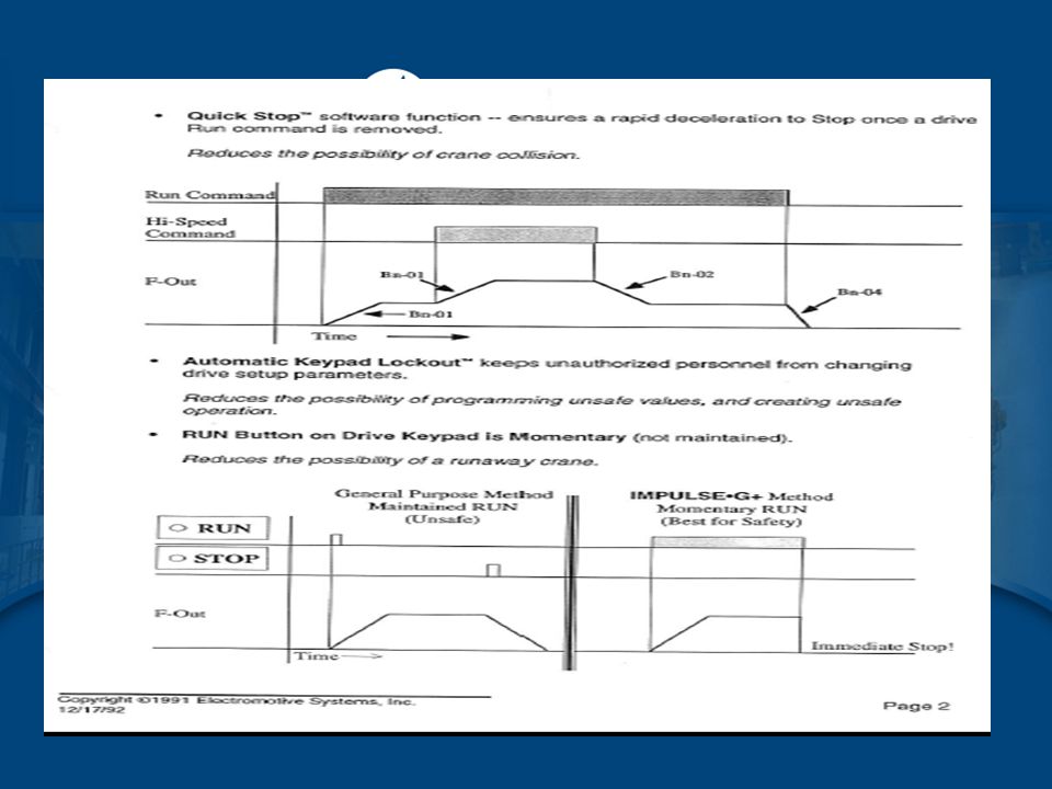


 4 Line by 18 Character fully.>")


900-2220. PSI Pump Systems Inc. 1(800)900-2220 Variable Frequency Drives Presented by PSI Pump Systems Inc. “ Your Solutions.>")


 TRANSFORMER RECTIFIER UNITS 3 rd HARMONIC REJECTION TRANSFORMERS (HRT) ULTRA HIGH ISOLATION TRANSFORMERS.>")
 M.Tech 1 st Year Textile Engineering.>")