Download presentation
Presentation is loading. Please wait.

1
Descriptive Geometry Eng. Areej Afeefy
Ref. Descriptive Geometry Metric PARE/LOVING/HILL Fifth edition

2
Descriptive Geometry Descriptive Geometry:
is the science of graphic representation and solution and space problems By Arch. Areej Afeefy

3
projections Two common types of projections:
1) perspective projections (used by architects or artists) 2) orthographic projections (perpendicular to the object)
 perspective projections (used by architects or artists) 2) orthographic projections (perpendicular to the object)")
4
Perspective Projection
Screen Human eye

5
Orthographic Projection
Screen

6
Orthographic Projection
Horizontal Front Profil

7
Horizontal Profil Front

8
Principal Views

9
Draw the profile

10
Steps to obtain a view Establish the line of sight.
Introduce the folding line Transfer distances to the new view Determine visibility and complete the view

11
Primary Auxiliary Views
Step 1: Establish the line of sight. Primary Auxiliary Views Step 2: Introduce the folding line Step 3: transfer distances a,e d,h y b,f c,g H 1 Step 4: determine visibility and complete view 1 D2 D1 D y h d g k1 e D2 c y f a f,e g,h D1 b b,a c,d

12
All views projected from top view has the same height dimension

13
Primary Auxiliary Views

14
View 1 is an auxiliary view projected from the front View

15
All the views projected from front view have the same depth dimension

17
Edge View of a plane

25
Chapter 3: LINES

28
Frontal Line

29
Frontal Line

30
the true angel between a line and any projection plane appears in any
view shows the line in true length and the projection plane in Edge View.

31
Level (Horizontal) Line
 Line")
32
Level Line

33
Profile Line

34
Profile Line

35
True Length of an Oblique Line

36
True Length of an Oblique Line

39
Bearing , Slope, and Grade
aH aH S55oE 55 b b Bearing: a term used to describe the direction of a line on the earth’s surface

40
Azimuth Bearing N aH aH 125o N125o b b

41
problem A 160-m segment AB of a power line has a bearing of N 60o and a downward slope of 20o from the given point A. Complete the front and top views. ah aF

42
D1 b 1 20o H 160 m N b N 60o a1 D1 ah H F D1 D1 aF b

45
Grade Grade: another way to describe the inclination of a line from the horizontal Plane

46
Grade

49
Chapter 4 Planes

50
Points and lines in Planes

51
Locating a Point in a Plane
Problem: Given the front and side views of a plane MON and the front view of a point A in the plane. Determine the side view n n m m aF x oF oP

52
Solution n n m Y m Y aF x aPx X X oF oP

53
Lines in Planes b g c aH e b aF c e Complete the front view

54
Lines in Planes b x g c aH e b aF x g c e

55
Principal Lines in Planes

56
Frontal Line All frontal lines in the same plane are parallel unless the plane it self is frontal

57
Horizontal or Level Lines

58
Horizontal or Level Lines
All horizontal lines in the same plane are parallel unless the plane it self is horizontal

59
Profile Line

60
Profile Line All profile lines in the same plane are parallel unless the plane it self is profile

61
Locus The Locus: is the path of a point, line or curve moving is some specified manner. Or it is the assemblage of all possible positions of a moving point, line or curve The locus of a point moving in a plane with a specified distance from another point is circle.

62
Locus Problem: in the given plane ABC locate a point K that lies 6 mm above horizontal line AB and 5 mm in front of frontal line AC. Scale: full size

63
Solution h c aH K 5 mm f f h b c f h h K 6 mm aF f b

64
Pictorial Intersection
B H D N E C K M Two principles to solve the problem: 1) Lines in a single plane must either be parallel or intersect. 2) If two planes are parallel, any lines on the planes in question are parallel.
 Lines in a single plane must either be parallel or intersect. 2) If two planes are parallel, any lines on the planes in question are parallel.")
65
Pictorial Intersection

66
Pictorial Intersection

67
Successive Auxiliary Views
Chapter 5 Successive Auxiliary Views

68
Construction of successive Auxiliary Views
Step 1: Establish the line of sight. Step 2: Introduce the necessary folding lines. Step 3: transfer distance to the new view. Step 4: Complete view.

69
Point View of a Line A line will appear in point view if the line of sight is parallel to the line in space.. In the drawing sheet, the line of sight should be parallel to the true length of the line.

70
Point View of a Line 2 b a2 ah b H a1,b F b T.L. Point View (P.V) aF 1
 aF 1")
71
Problem I Find the true clearance between the point O and the line AB.
1 a2,b Clearance b o o ah T.L. 2 H o F aF ah b o

72
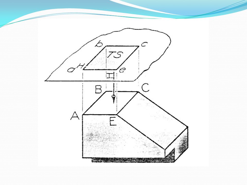
Edge View of a Plane A plane will appear in edge view in any view for which the line of sight is parallel to the plane. In the drawing sheet, a plane will appear in edge view in any view for which the line of sight is parallel to a true length line in the plane.

73
Edge View of a Plane c c h ah E.V. b a H F b c h b T.L. 1 aF

74
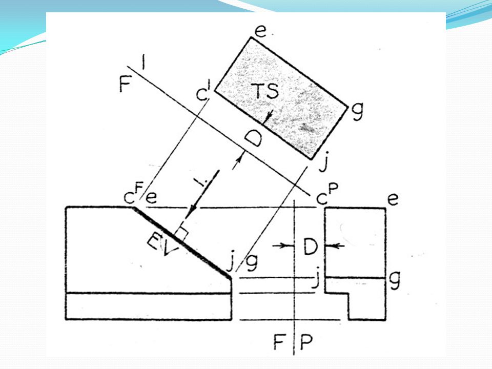
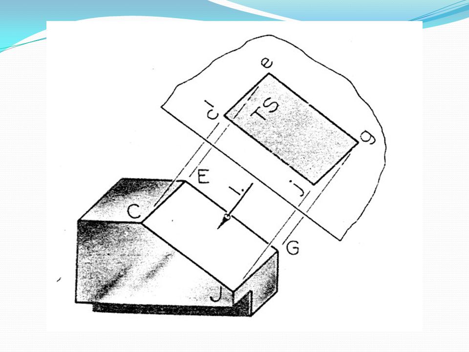
Normal Views of a Plane A normal view or TRUE SIZE and shape of a plane is obtained in any view for which the line of sight is perpendicular to the plane. In the drawing sheet the line of sight appear perpendicular to the Edge View of the plane.

75
Edge View of a Plane c 2 c h E.V. ah b a H b F c h b T.L. 1 aF
Normal View T.S. b a H F b c h b T.L. 1 aF

76
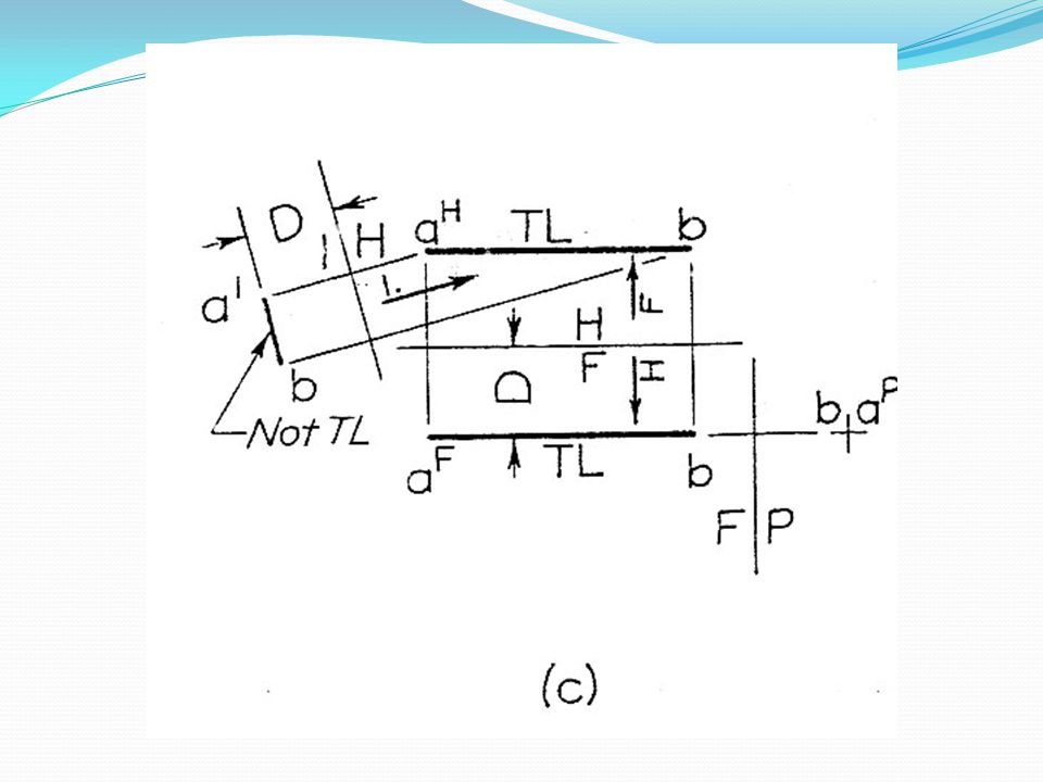
Uses of Auxiliary and additional Views
Position of line of sight In space On the drawing sheet 1) True length of line (TL) Perpendicular to line Perpendicular to any view of the line or directed to a point view of the line 2) Point view of line Parallel to line Parallel to the true length of the line 3) Edge view of plane (EV) Parallel to plane Parallel to true length of line in plane OR directed toward a true size view of plane 4) Normal or true size view of plane (TS) Perpendicular to plane Perpendicular to edge view of plane
 True length of line (TL) Perpendicular to line. Perpendicular to any view of the line or directed to a point view of the line. 2) Point view of line. Parallel to line. Parallel to the true length of the line. 3) Edge view of plane (EV) Parallel to plane. Parallel to true length of line in plane OR directed toward a true size view of plane. 4) Normal or true size view. of plane (TS) Perpendicular to plane. Perpendicular to edge view of plane.")
77
problem Find the front and top views of a 2.5m radius curve joining two intersecting lines BA & BC.

78
b a f b c c a c c b b TL f a a

79
b a 2 1 3 5 4 3 f 4 b c 2 5 c 1 a c c 1 1 2 2 b 3 b 3 TL f 4 4 5 5 a a

80
Chapter 6 Piercing Points

81
Piercing point The intersection of a line with a plane is called Piercing Point. If the line is not in or parallel to a plane, it must intersect the plane.

82
Piercing point - Auxiliary View Method
1. e b1,c c p e TL bH a p g g a a e p g c bF

83
Piercing point- Two View Method
A piercing point could be found using the given views as follows: (see the following Fig.) Any convenient cutting plane containing line EG is introduced, it appears EV in a principal view. The line of intersection between the two planes is determined. Since line EG and line both lies in the cutting plane they intersect, locating point P. Since line 1 – 2 also lies in Plane ABC, point P is the required Piercing Point.
 Any convenient cutting plane containing line EG is introduced, it appears EV in a principal view. The line of intersection between the two planes is determined. Since line EG and line both lies in the cutting plane they intersect, locating point P. Since line 1 – 2 also lies in Plane ABC, point P is the required Piercing Point.")
84
Piercing point- Two View Method
A Vertical cutting plane N 1 E P G C 2 B

85
Piercing point- Two View Method
a e 1 p c Vertical cutting plane N 2 bH g a 1 e p g c bF 2

86
Intersection of Planes
Chapter 7 Intersection of Planes

87
Intersection of Planes
Any two planes either parallel or must intersect. Even the intersection beyond the limits of planes. The intersection of planes result a line common to both of them.

88
Intersection of Planes Auxiliary view Method
bH e x k z a b1 f y k e g J x c a y j a c k g e c x z y f J g bF

89
Intersection of Planes Auxiliary view Method
bH e k z a bH y k e g J x c a y j a c k c g e z y J g bF

90
Intersection of Planes Two View - Piercing point Method
b b d d a a x x g g y y eF eP cF cP

91
Intersection of Planes Two View - Piercing point Method
b E.V. b d d L1 L1 2 a 2 a x x E.V. 1 1 g g 4 y y 4 3 3 eF eP cF cP

92
Intersection of Planes Two View - Piercing point Method
b b d d a a g g eF eP cF cP

93
Intersection of Planes Cutting Plane Method
Line of intersection m c H1 P1 2 3 1 4 H2 6 7 P2 5 b 8 n a o

94
Intersection of Planes Cutting Plane Method
cH m P1 2 1 3 4 6 P2 7 8 b nH LI o 5 a cF m 1 2 EV of HI P1 4 3 5 6 8 EV of H2 a P2 7 o b nH LI

95
Pictorial Intersection of Planes
3 a d s c k b e m 2 o

96
Pictorial Intersection Of Planes
3 a v c k b m 2

97
Chapter 8 Angle between Planes

98
Angle between Planes B θ m E.V. of m θ n E.V. of n A
P.V. of line of intersection AB Line of sight

99
Dihedral Angle Line of Intersection given
eH B e1 A TL LI eF g B LI e2g E.V. of A E.V. of B θ g

100
Dihedral Angle Line of Intersection is NOT given
4 o x 3 2 m kH y bH c 1 a EV.1 o n 3 4 x bF EV.2 2 y m 1 kF c

101
Dihedral Angle Line of Intersection is NOT given
b2 a n o X,y x m c θ kH n y bH m c a x o b1 a n TL o n x y k1 bF m y m kF c c

102
Dihedral Angle Line of Intersection is NOT given
Alternative solution: You can find the Edge View for both planes without resorting to find the line of intersection. See next slide

103
Dihedral Angle Line of Intersection is NOT given
Both Planes will Appear EV. a b2 n o a TS m kH o bH c c k2 TL n 3 a o n m 2 bF TL m kF n c m o k1 EV a b1,c 1

104
Angle between Oblique Plane and Principal Plane
EV of frontal plane b aH f c H F 1 F c a1 b θf c f TL b aF Angle between plane and frontal plane

105
Angle between Oblique Plane and Principal Plane
aH c H F P 1 c c TL b b aF f f b aP EV of Profile plane θP c a1 Angle between plane and Profile plane

106
Angle between Oblique Plane and Principal Plane
Angle between a plane and a horizontal plane can be measured in the similar fashion. The angle between sloping plane and a horizontal plane is called DIP ANGLE.

107
Angle between Oblique Plane and Principal Plane
1 aH b b θH aH TL c f c H F c f b aF Angle between plane and horizontal plane

108
Chapter 9 Parallelism

109
Parallel Lines Oblique Lines that appears parallel in two or more principal views are parallel in space.

110
Parallel Lines d b c aH H P F aF aP b b c c d d

111
Parallel Lines c b d aH H F F P aF b aP b c d d c

112
Principal Line Two horizontal, two frontal, or two profile lines that appears to be parallel in two principal views may or may not be parallel in space. non intersecting, non parallel lines are called SKEW LINES.

113
Parallel Lines aH X a1b e c X b 1 X c P H F F P aF aP X c X c b b

114
Parallel Lines aH X e X a1b e c X b D2 1 X c P D1 H F F P aF D1 D2 aP

115
Parallel Planes n c mH f b aH o H 1 F o b aF a1 o b TL c mF f c m1 n n

116
Parallel Planes If two planes are parallel, any view showing one of the planes in edge view must also show the other plane as parallel edge view. Parallel edge views prove that planes are parallel.

117
Lines parallel to planes Planes parallel to lines
If two lines are parallel, any plane containing one of the lines is parallel to the other line. A line may be drawn parallel to a plane by making it parallel to any line in the plane.

118
Lines parallel to planes Planes parallel to lines
y r m x q p x q m o y p r

119
Chapter 10 Perpendicularity

120
Perpendicular Lines If a line is perpendicular to a plane, it is perpendicular to every line in the Plane. e y1 g 90 90 y f j x1 x Perpendicular lines are not necessarily intersecting lines and they do not necessarily Lie in the same plane.

121
Perpendicular Lines If two lines are perpendicular, they appear perpendicular in any view showing at least one of the lines in true length. If two lines appear perpendicular in a view, they are actually perpendicular in space if at least one of the lines is true length in the same view.

122
Perpendicular Lines n H 1 s m o n s H o F o TL n s m m

123
Plane Perpendicular to Line Two-View Method
A plane is perpendicular to a line if the plane contains two intersecting lines each of which is perpendicular to the given line.

124
Plane Perpendicular to Line Two-View Method
y h TL z x f H F x h z TL z f y xf EV F h TL 1 y

125
Plane Perpendicular to Line Auxiliary-View Method
k z x H h F x z k z y x EV F k h TL 1 y

126
Line Perpendicular to Plane Two-View Method
A line perpendicular to a plane is perpendicular to all lines in the plane.

127
Line Perpendicular to Plane Two-View Method
f TL o m k H F o a TL k m h f k n

128
Line Perpendicular to Plane Auxiliary-View Method
TL EV n m a k h TL o o m H k F o a k m h k n

129
Common Perpendicular Point View Method
The shortest distance from a point to a line is measured along the perpendicular from the point to a line. The shortest distance between two skew lines is measured by a line perpendicular to each of them.

130
Common Perpendicular Point View Method
b e 1 2 a e H e ab x b F TL a c a e c c b

131
Common Perpendicular Point View Method
b x e 1 y 2 a e x TL H e ab x x b F TL a c y a x e c y c b

132
Common Perpendicular Plane Method
Another method to find the shortest distance between skew lines, specially when the perpendicular view are not required.

133
Common Perpendicular plane Method
1 c x kh Shortest Distance b k EV TL c h b e e a H a F a e h k c b

134
Shortest line at specified Grade connecting Two Skew Lines
1 c h TL p c e EV b x ph b a e H Shortest Horizontal Distance F b h a c h p a e

135
Shortest line at specified Grade connecting Two Skew Lines
1 c h TL p c e EV b x ph b a 100 e H F b h a c 15 h p a e

136
Projection of line on a Plane
The projection of a point on a plane is the point in which a perpendicular from the point to the plane pierces the plane.

137
Projection of line on a Plane
m m 1 ap ap TL b b n n a bp bp h h b TL o o ev F P o m bp ap n

138
o 2 1 b k X v 3 a 4 n m k 2 o b X v 1 a 4 3 m n

Similar presentations