Download presentation
Presentation is loading. Please wait.

1
Industrial Engineering Program King Saud University
IE433 CAD/CAM Computer Aided Design and Computer Aided Manufacturing Part-10 Industrial Engineering Program King Saud University

2
Before you can fully understand CNC, you must first understand how a manufacturing company processes a job that will be produced on a CNC machine. The following is an example of how a company may break down the CNC process .

3
FLOW OF CNC PROCESSING 1. Obtain or develop the part drawing. 2
FLOW OF CNC PROCESSING 1. Obtain or develop the part drawing. 2. Decide what machine will produce the part. 3. Decide on the machining sequence. 4. Choose the tooling required. 5. Do the required math calculations for the program coordinates. 6. Calculate the speeds and feeds required for the tooling and part material. 7. Write the NC program. 8. Prepare setup sheets and tool lists. 9. Send the program to machine. 10. Verify the program. 11. Run the program if no changes are required

4
PREPARING A PROGRAM A program is a sequential list of machining instructions for the CNC machine to execute. These instructions are CNC code that consists of blocks (also called lines). Each block contains an individual command for a movement or specific action. As with conventional machines, one movement is made before the next one. This is why CNC codes are listed sequentially in numbered blocks.
. Each block contains an individual command for a movement or specific action. As with conventional machines, one movement is made before the next one. This is why CNC codes are listed sequentially in numbered blocks.")
5
The following is a sample CNC milling program
The following is a sample CNC milling program. Note how each block is numbered and usually contains only one specific command. The blocks are numbered in increments of 5 (this is the software default on startup). Each block contains specific information for the machine to execute in sequence. Workpiece Size: X4, Y3, Z1 Tool: Tool #3, 3/8" Slot Drill Tool Start position: X0, Y0, Z1.0 % (Program Start Flag) : (Program #1002) N5 G90 G20 G40 G17 (Block #5, Absolute in Inches) N10 M06 T3 (Tool Change to Tool #3) N15 M03 S (Spindle on CW at 1250 RPM) N20 G00 X1.0 Y1.0 (Rapid over to X1.0, Y1.0) N25 Z (Rapid down to Z0.1) N30 G01 Z F5 (Feed down to Z at 5ipm) N35 X3.0 Y2.0 F (Feed diagonally to X3.0, Y2.0 at 10ipm) N40 G00 Z (Rapid up to Z1.0) N45 X0 Y0 (Rapid over to X0, Y0) N50 M05 (Spindle Off) N55 M30 (Program End)
. Each block contains specific information for the machine to execute in sequence. Workpiece Size: X4, Y3, Z1. Tool: Tool #3, 3/8 Slot Drill. Tool Start position: X0, Y0, Z1.0. % (Program Start Flag) :1002 (Program #1002) N5 G90 G20 G40 G17 (Block #5, Absolute in Inches) N10 M06 T3 (Tool Change to Tool #3) N15 M03 S1250 (Spindle on CW at 1250 RPM) N20 G00 X1.0 Y1.0 (Rapid over to X1.0, Y1.0) N25 Z0.1 (Rapid down to Z0.1) N30 G01 Z F5 (Feed down to Z at 5ipm) N35 X3.0 Y2.0 F10.0 (Feed diagonally to X3.0, Y2.0 at 10ipm) N40 G00 Z1.0 (Rapid up to Z1.0) N45 X0 Y0 (Rapid over to X0, Y0) N50 M05 (Spindle Off) N55 M30 (Program End)")
6
CNC CODES There are two major types of CNC codes, or letter addresses, in any program. The major CNC codes are called G-codes and M-codes. G-codes are preparatory functions, which involve actual tool moves (for example, control of the machine). These include rapid moves, feed moves, radial feed moves, dwells, roughing, and profiling cycles. M-codes are miscellaneous functions, which include actions necessary for machining but not those that are actual tool movements (for example, auxiliary functions). These include actions such as spindle on and off, tool changes, coolant on and off, program stops, and related functions.
. These include rapid moves, feed moves, radial feed moves, dwells, roughing, and profiling cycles. M-codes are miscellaneous functions, which include actions necessary for machining but not those that are actual tool movements (for example, auxiliary functions). These include actions such as spindle on and off, tool changes, coolant on and off, program stops, and related functions.")
7
Each designation used in CNC programming is called a letter address
Each designation used in CNC programming is called a letter address. The letters used for programming are as follows: N Block Number: Specifies the start of a block G Preparatory function, as previously explained X X Axis Coordinate Y Y Axis Coordinate Z Z Axis Coordinate I X Axis location of Arc center J Y Axis location of Arc center K Z Axis location of Arc center S Sets the spindle speed F Assigns a feedrate T Specifies tool to be used M Miscellaneous function, as previously explained

8
THREE MAJOR PHASES OF A CNC PROGRAM
The three phases of a CNC program are: (1) Program setup: contains all the instructions that prepare the machine for operation (2) Material removal: deals exclusively with the actual cutting feed moves (3) System shutdown: contains the G- and M-codes that turn off all the options that were turned on in the setup phase.
 Program setup: contains all the instructions that prepare the machine for operation. (2) Material removal: deals exclusively with the actual cutting feed moves. (3) System shutdown: contains the G- and M-codes that turn off all the options that were turned on in the setup phase.")
9
Program setup N10 M06 T2 Material removal N25 Z0.125
The following shows the three major phases of a CNC program. % :1001 N5 G90 G20 Program setup N10 M06 T2 N15 M03 S1200 N20 G00 X1.00 Y1.00 Material removal N25 Z0.125 N30 G01 Z F5.0 N35 G01 X2.0 Y2.0 N40 G00 Z1.0 N45 X0 Y0 System shutdown N50 M05 N55 M30

10
Examine the following program to see how it was written.
% :1001 N5 G90 G20 N10 M06 T1 N15 M03 S1200 N20 G00 X1 Y1 Z0.125 N25 G01 Z F5.0 N30 G01 X3.0 N35 G01 Y2.0 N40 G01 X1 N45 G01 Y1 N50 G01 Z-0.25 N55 G01 X3 N60 Y2 N65 X1 N70 Y1 N75 G00 Z0.050 N80 G00 Z1 N85 X0 Y0 N85 M05 N90 M30 Program Start Flag Program Number Use Absolute Coordinates and inch programming Tool change, use Tool #1. Turn spindle on CW at 1200 RPM Rapid move to X1 Y1 Z Feed down into the part 0.125" at 5 ipm Feed to X3 (still at 5 ipm) Feed to Y2 (still at 5 ipm) Feed back to X1 Feed back to Y1 Feed down to Z-0.25" (still at 5 ipm) Feed across to X3 Feed to Y2 (The G01 is MODAL) Feed back to X1 (G01 is still MODAL) Feed to start point at Y1 Rapid to Z0.05 Rapid tool up to Z1 or clearance plane Rapid to home position Turn spindle off End of program
 Feed to Y2 (still at 5 ipm) Feed back to X1 Feed back to Y1 Feed down to Z-0.25 (still at 5 ipm) Feed across to X3 Feed to Y2 (The G01 is MODAL) Feed back to X1 (G01 is still MODAL) Feed to start point at Y1 Rapid to Z0.05 Rapid tool up to Z1 or clearance plane Rapid to home position Turn spindle off End of program.")
11
USING A PROGRAMMING SHEET
You use the CNC program sheet to prepare the CNC program. Doing so simplifies the writing of the CNC program EQUIVALENT CNC BLOCKS --> N5 G20 G90 N10 T02 M06 N15 M03 S1200 N20 G00 X0 Y0 N25 Z0.1 N30 G01 Z-0.1 F2.0 N35 G01 X1.5

12
BLOCK FORMAT Block format is often more important than program format. It is vital that each block of CNC code be entered into the CPU correctly. Each block comprises different components, which can produce tool moves on the machine. Following is a sample block of CNC code. Examine it closely and note how it is written. N135 G01 X1.0 Y1.0 Z0.125 F5.0 N135 Block Number Shows the current CNC block number. G01 G-Code The G-code is the command that tells the machine what it is to do in this case, a linear feed move. X1.0 Y1.0 Z Coordinate. This gives the machine an endpoint for its move. X designates an X axis coordinate. Y designates a Y coordinate. Z designates a Z coordinate. F5.0 Special Function. Any special function or related parameter is to be included here. In this case, a feed rate of 5 inches per minute is programmed.

13
There are some simple restrictions to CNC blocks:
Each may contain only one tool move. Each may contain any number of nontool move G-codes, provided they do not conflict with each other (for example, G42 and G43). Each may contain only one feedrate per block. Each may contain only one specified tool or spindle speed. The block numbers should be sequential. Both the program start flag and the program number must be independent of all other commands. The data within a block should follow the sequence shown in the above sample block, N-block number, G-code, any coordinates, and other required functions. Each may contain only one M-code per block.
. Each may contain only one feedrate per block. Each may contain only one specified tool or spindle speed. The block numbers should be sequential. Both the program start flag and the program number must be independent of all other commands. The data within a block should follow the sequence shown in the above sample block, N-block number, G-code, any coordinates, and other required functions. Each may contain only one M-code per block.")
14
PREPARING TO PROGRAM Before you write a CNC program, you must first prepare to write it. The success of a CNC program is directly related to the preparation that you do before you write the CNC program. You should do three things before you begin to write a program: Develop an order of operations. Do all the necessary math and complete a coordinate sheet. Choose your tooling and calculate speeds and feedrates.

15
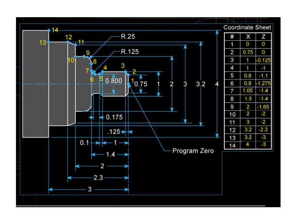
The CNC operator can also use coordinate and setup sheets
The CNC operator can also use coordinate and setup sheets. Using them as references makes generation of the CNC program easier.

16
Program zero allows you to specify a position from which to start or to work. Once program zero has been defined, all coordinates used in a program will be referenced from this point. When you work from a constant program zero, you are using absolute programming. In incremental programming, you have in effect a floating program zero that changes at all times To specify absolute positions in the X direction, use the X-address word. To specify absolute positions in the Y and Z directions, use the Y- and Z-address words, respectively. The position selected for milling is always the lower left-hand corner and top surface of the workpiece. The position used for the lathe is always the center of the part in X and the right-hand end of the finished workpiece in Z.

19
TOOL MOTION Generally, three types of tool motion are used on a CNC machine: G00 Rapid tool move. Nonmachining command. Each axis trajectory is exhausted as fast as the motor can drive the axes. G01 Straight-line feed move. Linear interpolation. Coordinated moves at a controlled feedrate. G02/G03 Two-dimensional arc feed moves. Circular interpolation.

20
TOOL MOTION

21
USING CANNED CYCLES Canned, or fixed program, cycles are aids that simplify programming. Canned cycles combine many standard programming operations and are designed to shorten the program length, minimize math calculations, and optimize cutting conditions to improve the efficiency of the machine. Examples of canned cycles on a mill are drilling, boring, spot facing, tapping, and so on; on a lathe, threading, rough facing and turning, and pattern repeating cycles. On the lathe, canned cycles are also referred to as multiple repetitive cycles. You will find examples of these cycles as you work through the milling and turning sections.

22
USING CANNED CYCLES

23
Tooling Not all cutting operations can be performed with a single tool. Separate tools are used for roughing and finishing, and tasks such as drilling, slotting, and thread cutting require their own specific tools. The correct cutting tool must be used at all times. The size and shape of the cutting tools that you can use depend on the size and shape of the finished part. A tool manufacturer's catalog will give you a complete list of the various types of tools available and the applications of each Remember: The depth of cut that can be taken depends on the workpiece material, the coolant, the type of tool, and the machine tool itself.

24
Tooling The tool most often used to make holes is the fluted drill. Drills are made with two, three, or four cutting lips. The two-lip drill is used for drilling solid stock. The three- and four-lip drills are used for enlarging holes that have been previously drilled. Modern drills can also have coolant holes for direct delivery of coolant through the end of the drill.

25
Tooling The rotating cutter, termed the milling cutter, has almost an unlimited variety of shapes and sizes for milling regular and irregular forms. The most common milling cutter is the end mill. Other tools that are often used are shell mills, face mills, and roughing mills. When milling, care must be taken not to take a cut that is deeper than the milling cutter can handle. End mills come in various shapes and sizes, each designed to perform a specific task. The three basic shapes of standard end mills are flat, ballnose, and bullnose.

26
Tooling In lathe operations, the tool is driven through the material to remove chips from the workpiece in order to leave geometrically true surfaces. The type of surface produced by the cutting operation depends on the shape of the tool and the path it follows through the material. When the cutting edge of the tool breaks down, the surface finish becomes poor and the cutting forces rise. Vibration and chatter are definite signs of tool wear, although many forces such as depth of cut, properties of materials, friction forces, and rubbing of the tool nose also affect tool vibration.

27
FEEDRATES AND SPINDLE SPEEDS
It is very important to fully understand the value of the correct feedrate and spindle speed. Too fast a speed or feedrate will result in early tool failure or poor surface finish. Too slow a speed or feedrate will lead to increased machining time and, possibly, greater part cost. New tool technology has produced a wide range of tools that can be used at greater speeds and feed rates for longer periods. For milling, the correct speeds and feed rates are determined in part by the diameter of the cutter, spindle RPM, number of teeth on the cutter, chip load per tooth, and surface feet per minute for a particular material. For turning, the diameter of the workpiece and the surface feet per minute for the material are factors in determining the proper speeds and feed rates.

28
CUTTING FLUIDS There are three main reasons for using cutting fluid
To remove or reduce the heat being produced To reduce cutting tool wear To help clear chips from the workpiece area

29
End of Part -10

Similar presentations


 Computer Numerical Control (CNC)>")


