Download presentation
Presentation is loading. Please wait.

1
I2 Medical imaging

2
X-rays X-rays pass through human (or dog) flesh very easy, but do not pass through bone as easily.
 flesh very easy, but do not pass through bone as easily.")
3
Absorption Light passing through a solid is absorbed if the photon energy is enough to increase the energy of an electron so it can jump from a low energy level to a higher one.

4
Absorption Since light photons have an energy about the same as an electron transition (1 eV approx) most are absorbed.
 most are absorbed.")
5
X-ray photons X-ray photons have much more energy (>120 eV)
They can knock electrons out of the atom in 2 ways

6
1. Photoelectric effect X-ray photon is completely absorbed – giving all of its energy to the KE of the electron (minus the work function of course)
 .")
7
2. Compton scattering The photon gives some of its energy to the electron and continues with less energy and so longer wavelength (E = hf = hc/λ)
 .")
8
2. Compton Scattering

9
Attenuation

10
Attenuation Reduction in X-ray intensity with thickness 100
# interaction is proportional to the # photons, so the curve is exponential decay Number of photons x 1015 50 3 Thickness/cm 6 3

11
Attenuation coefficient
I = I0e-μx where I0 = the original intensity x = distance through absorber μ = attenuation coefficient

12
Half-value thickness x½
Thickness required to reduce the intensity to half its original intensity I = I0/2 = I0e-μx½ Taking logs x½ = ln2/μ = 0.693/μ Half value thickness depends on the energy of the X-rays and the substance

13
Example A parallel beam of X-rays of intensity 0.2 kW.m-2 is passed through 5 mm of a material of half-value thickness 2 mm. Calculate the intensity of the beam. HL Physics, C. Hamper, Pearson 2009

14
Example First calculate the attenuation coefficient μ
A parallel beam of X-rays of intensity 0.2 kW.m-2 is passed through 5 mm of a material of half-value thickness 2 mm. Calculate the intensity of the beam. First calculate the attenuation coefficient μ μ = 0.693/x½ = 0.693/2 = 0.35 mm-1 I = I0e-μx = 0.2e-0.35x5 = kW.m-2 HL Physics, C. Hamper, Pearson 2009

15
Taking an X-ray picture

16
Taking an X-ray picture
Have to choose X-rays of the right intensity/energy X-rays are dangerous (ionising) – need to keep exposure time and intensity to a minimum Simplest way is to place broken part on photographic film (which is enclosed in a light proof box
 – need to keep exposure time and intensity to a minimum. Simplest way is to place broken part on photographic film (which is enclosed in a light proof box.")
17
Black areas are where lots of photons hit the photographic film and “exposed” it
Few X-ray photons travelled through and hit paper

18
Intensifying screen A screen of fluorescent material which gives out visible light when X-rays hit it is put on either side of the photographic film. This means X-rays of lower intensity can be used.

19
Barium Meal To help see soft-tissue such as the gut, it can be filled with a material with is opaque to X-rays like barium sulphate. Drinking a “barium meal”

20
Digital images A array of photosensitive diodes works in a similar way to a CCD. They gain charge when exposed to X-rays. This produces a p.d. which can be converted to a digital signal.

21
Digital images The digital image can be enhanced and coloured electronically – as in airport security.

22
Tomography For parts deep in the body a “slicing” technique called tomography can be used

23
Tomography

24
Computer Tomography (CT scan)
")
25
Computer Tomography (CT scan)
X-ray source and a circular array of sensors are rotated around the patient

26
Computer Tomography (CT scan)
By moving along the length of the body and using computers to analyse the digital signals a complete 3-D image can be built.

27
Let’s try a worksheet

28
Ultrasound

29
Ultrasound Higher frequency than a healthy human can hear (>20 kHz). Ultrasounds are reflected off different layers in the body and a picture is built up.

30
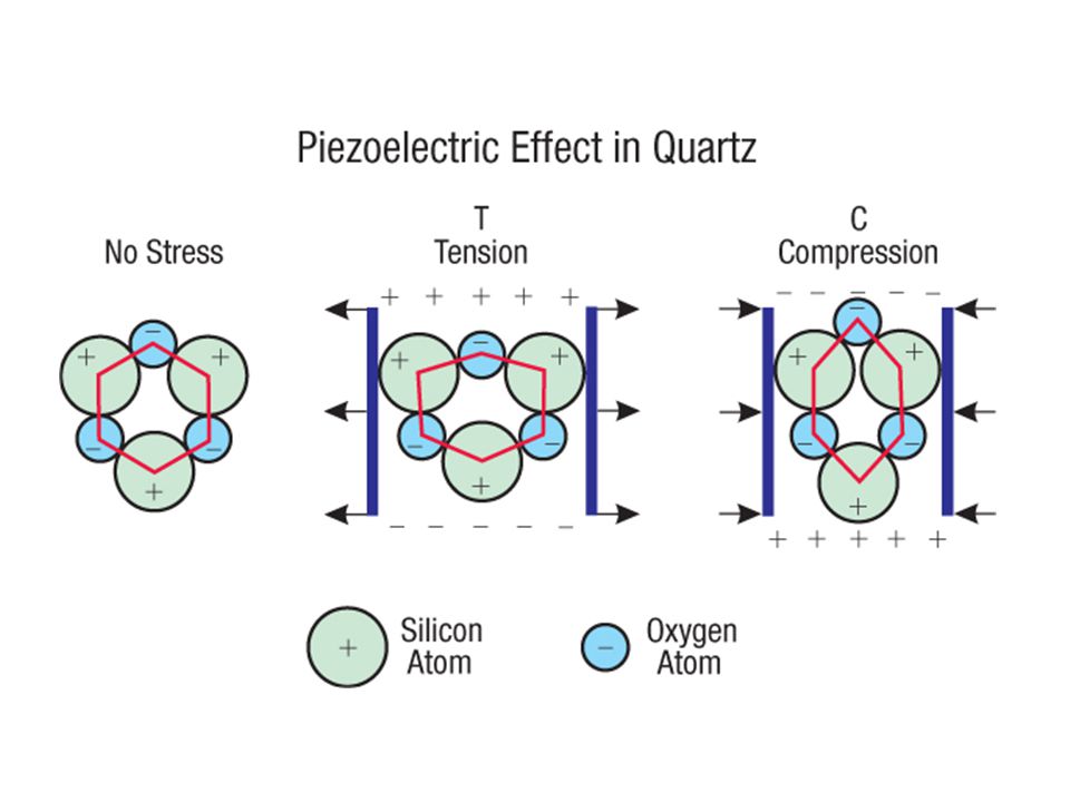
Piezoelectric effect When a quartz crystal is stretched, a p.d. is produced (due to polarisation of the molecules in the crystal) If a p.d. is applied, the same happens, the quartz is deformed.

31
Piezoelectric effect

32
Piezoelectric effect

33
Piezoelectric effect

34
Piezoelectric effect

36
Ultrasound production
An alternating p.d. of frequency >20 kHz is applied to a quartz crystal causing it to vibrate

37
Ultrasound detection A sound wave causes a crystal to vibrate, producing an alternating p.d.

38
Reflections Because the reflections are analysed, the transmitter and receiver are in the same place. The same crystal can be used as transmitter and receiver if pulsed signals are used that are short enough so the reflected wave returns before a new pulse is produced.

39
Example If the pulse length is 10-6 s and the speed of sound in body tissue is 1500 m.s-1 then the minimum distance the wave can travel before the pulse has finished transmitting is 1500 x 10-6 = 1.5 mm. So it could be reflected off something at a depth of 0.75 mm. This is fine!

40
Frequency? Need to use a short wavelength to avoid the wave spreading out from diffraction. Smallest object a doctor might be interested in is around a few mm, so wavelength needs to be a bit less. If λ = 1mm and velocity = 1500 m.s-1 then f = 1500/10-3 = 1.5 MHz.

41
Frequency Higher frequencies would give higher resolution but are absorbed easier (higher attenuation). Operator adjusts frequency and pulse length to get the best image for organs of different depth and size.
. Operator adjusts frequency and pulse length to get the best image for organs of different depth and size.")
42
Acoustic impedance When ultrasound is incident on a boundary between two media (materials), part of the wavefront is reflected and part refracted.

43
Acoustic impedance - Z The percentage reflected depends upon the relative acoustic impedance of the two media. Acoustic impedance (Z) = ρc where ρ = density of medium c = the velocity of the ultrasound Unit of Z = kg.m-2.s-1
 = ρc. where ρ = density of medium. c = the velocity of the ultrasound. Unit of Z = kg.m-2.s-1.")
44
Acoustic impedance The greater the difference in acoustic impedance, the greater the % reflection.

45
Acoustic impedance The greater the difference in acoustic impedance, the greater the % reflection. The difference between air and skin is great. To prevent all of the ultrasound being reflected by the skin, gel is used to fill the gap between the transmitter and the skin.

46
A - scans A plot of strength of reflected beam against time
Signal strength Time

47
A - scans organ probe The depth and thickness of the organ can be deduced from the times of the reflected pulse tissue gel

48
A - scans Notice the 2nd pulse is smaller due to attenuation organ
probe Notice the 2nd pulse is smaller due to attenuation tissue gel

49
A - scans organ probe The last pulse is large as most of the ultrasound is reflected by the last boundary tissue gel

50
A - scans organ probe To gain more information the probe can be moved up and down to reveal the size, shape and changes in thickness of the organ. tissue gel

51
A - scans organ probe To gain more information the probe can be moved up and down to reveal the size, shape and changes in thickness of the organ. tissue gel

52
B - scans An A scan gives information but not an image. B – scans converts the signal into a dot whose brightness corresponds to the strength of the signal. By sweeping the probe across the organ an image can be produced.

53
3-D ultrasound An array of probes moved around the patient can be used to construct a 3D image using a computer.

54
Questions!

Similar presentations


>")
