Download presentation
Presentation is loading. Please wait.

1
Zhongkai Chen

2
Appears in: VLSI Design, Automation and Test, 2007. VLSI-DAT 2007. International Symposium on Date:25-27 April 2007 Zi-Yi Zhao, Chien-Hung Lin, Yu-Zhi Xie, Yen- Ju Chen, Yi-Jie Lin, and Shu-Chung Yi. National Changhua University of Education, Changhua, Taiwan 500, ROC

3
Introduction BA (Binary to Abacus) Module PA (Parallel Addition) Module TB (Thermometric to Binary) Module Example Extension to 4n-Bit Adder Results
 Module PA (Parallel Addition) Module TB (Thermometric to Binary) Module Example Extension to 4n-Bit Adder Results")
4
The first digital arithmetic circuits employing the method of the Chinese abacus were proposed on 1998. The most drawback is the delay time due to serial addition of each bead by the Shift-Up module

5
(a) Chinese abacus coding with base 10 of the decimal number 6 (b) the proposed Chinese abacus adder coding with base 16 of the decimal number 9 5 1 4 1
 Chinese abacus coding with base 10 of the decimal number 6 (b) the proposed Chinese abacus adder coding with base 16 of the decimal number")
6
Block diagram of the 4-bit abacus adder

7
This module converts a 4-bit binary number (I 3 I 2 I 1 I 0 ) 2 into an abacus representation (H 2 H 1 H 0 | L 2 L 1 L 0 ) abacus. H2H1H0 and L2L1L0 are determined by: H 2 =I 3 I 2, H 1 =I 3, H 0 =I 3 +I 2 L 2 =I 1 I 0, L 1 =I 1, L 0 =I 1 +I 0 Where 0≤H 2 ≤H 1 ≤H 0 ≤1, and 0 ≤L 2 ≤L 1 ≤L 0 ≤1. H 2 H 1 H 0 :Higher Beads L 2 L 1 L 0 : Lower Beads

8
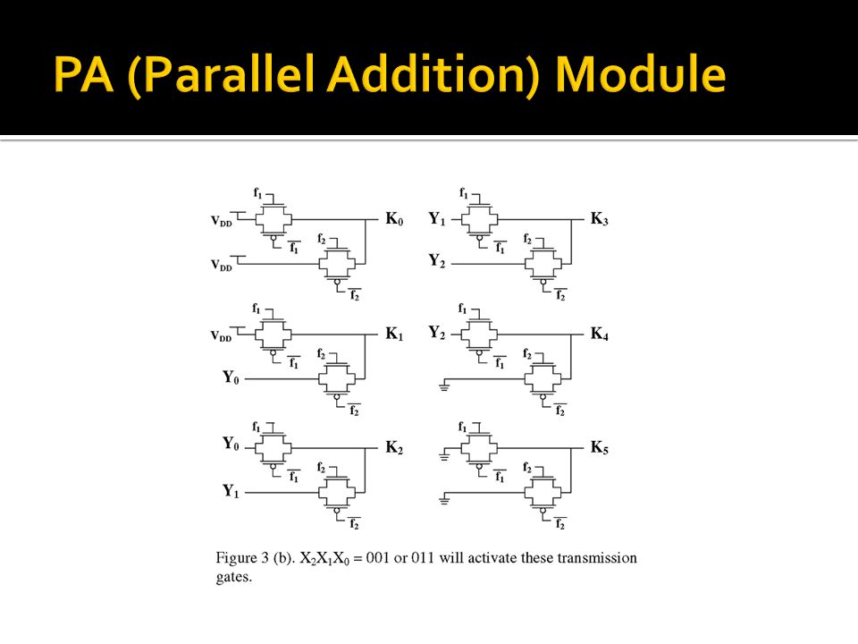
This block can parallel add two abacus numbers simultaneously. The sum of (X 2 X 1 X 0 ) and (Y 2 Y 1 Y 0 ) will then be represented as the thermometric transformation (K 5 K 4 K 3 K 1 K 0 ), where 0 ≤K i ≤K j ≤1 for i>j.
 and (Y 2 Y 1 Y 0 ) will then be represented as the thermometric transformation (K 5 K 4 K 3 K 1 K 0 ), where 0 ≤K i ≤K j ≤1 for i>j..")
9
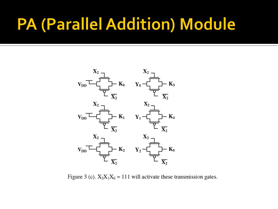
The behavior of PA module is modeled in the following equations: 1.This module acts similarly as a multiplexer. The addend X 2 ~X 0 2.are as signal selectors to modify the configuration of augend Y 2 ~Y 0. 3.The thermometric results will be then represented in K 5 ~K 0. 4.There are only four configurations of addend (X 2 X 1 X 0 ), i.e., (000), (001), (011), or (111).
, i.e., (000), (001), (011), or (111)..")
13
This module transforms thermometric representation to binary numbers. The outputs O 1, O o and C 0ut are determined by the following equations: O 0 =K 0 ∙C in +K 1 ∙K 0 ∙C in +K 2 ∙K 1 ∙C in +K 3 ∙K 2 ∙ C in +K 4 ∙K 3 ∙C in +K 5 ∙K 4 ∙C in +K 5 ∙C in O 1 =K 5 +K 4 ∙C in +K 2 ∙K 0 ∙C in +K 4 ∙K 1 ∙C in C out =K 3 + K 2 ∙C in

14
9=>(1001)13=> (1101) (1001)+(1101) BA Module: BA1: (1001) 2 =(011|001) abacus BA2: (1101) 2 =(111|001) abacus PA Module: PA1: X2=0 X1=1 X0=1 Y2=1 Y1=1 Y0=1 PA2: X2=0 X1=0 X0=1 Y2=0 Y1=0 Y0=1
13=> (1101) (1001)+(1101) BA Module: BA1: (1001) 2 =(011|001) abacus BA2: (1101) 2 =(111|001) abacus PA Module: PA1: X2=0 X1=1 X0=1 Y2=1 Y1=1 Y0=1 PA2: X2=0 X1=0 X0=1 Y2=0 Y1=0 Y0=1")
15
PA1: X2=0 X1=1 X0=1, Y2=1 Y1=1 Y0=1, f1=X2X1=1, f2=X1X0=0 K0=1, K1=1, K2=Y0=1, K3=Y1=1, K4=Y2=1 K5=0

16
PA2: X2=0 X1=0 X0=1, Y2=0 Y1=0 Y0=1, f1=X2X1=0 f2=X1X0=1 K0=1 K1=Y0=1 K2=Y1=0 K3=Y2=0 K4=0 K5=0

17
TB Module: TB2: Cin=0, K0=1 K1=1 K2=0 K3=0 K4=0 K5=0 O0=…=0+0+0+0+0+0+0=0 O1=…=0+0+0+1=1 Cout=…=0 O 0 =K 0 ∙C in +K 1 ∙K 0 ∙C in +K 2 ∙K 1 ∙C in +K 3 ∙K 2 ∙C in +K 4 ∙K 3 ∙C in +K 5 ∙K 4 ∙C in +K 5 ∙C in O 1 =K 5 +K 4 ∙C in +K 2 ∙K 0 ∙C in +K 4 ∙K 1 ∙C in C out =K 3 + K 2 ∙C in O 0 =K 0 ∙C in +K 1 ∙K 0 ∙C in +K 2 ∙K 1 ∙C in +K 3 ∙K 2 ∙C in +K 4 ∙K 3 ∙C in +K 5 ∙K 4 ∙C in +K 5 ∙C in O 1 =K 5 +K 4 ∙C in +K 2 ∙K 0 ∙C in +K 4 ∙K 1 ∙C in C out =K 3 + K 2 ∙C in

18
TB1 Cin=0, K0=1, K1=1, K2=1, K3=1, K4=1 K5=0 O0=…=0+0+0+0+0+1+0=1 O1=…=0+0+0+0=0 Cout=…=1+0=1 Final Answer: (10110) 2 =22 O 0 =K 0 ∙C in +K 1 ∙K 0 ∙C in +K 2 ∙K 1 ∙C in +K 3 ∙K 2 ∙C in +K 4 ∙K 3 ∙C in +K 5 ∙K 4 ∙C in +K 5 ∙C in O 1 =K 5 +K 4 ∙C in +K 2 ∙K 0 ∙C in +K 4 ∙K 1 ∙C in C out =K 3 + K 2 ∙C in O 0 =K 0 ∙C in +K 1 ∙K 0 ∙C in +K 2 ∙K 1 ∙C in +K 3 ∙K 2 ∙C in +K 4 ∙K 3 ∙C in +K 5 ∙K 4 ∙C in +K 5 ∙C in O 1 =K 5 +K 4 ∙C in +K 2 ∙K 0 ∙C in +K 4 ∙K 1 ∙C in C out =K 3 + K 2 ∙C in
 2 =22 O 0 =K 0 ∙C in +K 1 ∙K 0 ∙C in +K 2 ∙K 1 ∙C in +K 3 ∙K 2 ∙C in +K 4 ∙K 3 ∙C in +K 5 ∙K 4 ∙C in +K 5 ∙C in O 1 =K 5 +K 4 ∙C in +K 2 ∙K 0 ∙C in +K 4 ∙K 1 ∙C in C out =K 3 + K 2 ∙C in O 0 =K 0 ∙C in +K 1 ∙K 0 ∙C in +K 2 ∙K 1 ∙C in +K 3 ∙K 2 ∙C in +K 4 ∙K 3 ∙C in +K 5 ∙K 4 ∙C in +K 5 ∙C in O 1 =K 5 +K 4 ∙C in +K 2 ∙K 0 ∙C in +K 4 ∙K 1 ∙C in C out =K 3 + K 2 ∙C in")
19
Generally, conventional fast adders of high bit number are all connected by 4-bit unit adders. The Chinese abacus adder can also extend to 4n-bit adder by CLA-like or conditional-sum-adder-like methods. Replace it with Abacus Adder Extend both A and B to 4 bits The C out of CLA: C i+1 =G i +P i C i The C out of Abacus Adder: C out =K 3 +K 2 C in Compared the above two equations, the 4-bit basic unit abacus adder can be extended to a 4n-bit CLA-like abacus adder

20
The delay of the 8-bit abacus adders are 22%, and 14% less than those of CLA adders for 0.35um, and 0.18um technologies, respectively. The power consumption of the abacus adders are 30%, and 60% less than those of CLA adders for 0.35um, and 0.18um technologies, respectively. The transistor count of abacus adder is similar to that of CLA

21
The delays of the 32-bit abacus adder are 17%, and 12% less than those of CLA adder for 0.35um, and 0.18um technologies, respectively.

22
Thank you. Questions?

Similar presentations


10.>")


 contains datapath unit and control unit. Datapath: A.>")

>")
 Randy H. Katz University of.>")


