Download presentation
Presentation is loading. Please wait.

1
3-D Computational Vision CSc 83020 Image Processing II - Fourier Transform

2
CSc 83020 3-D Computer Vision / Ioannis Stamos The Fourier Transform Previous lecture: filtering in the spatial domain. A signal (i.e. scanline/audio/image) has equivalent representation in the Frequency Domain. Spatial domain Frequency domain
 has equivalent representation in the Frequency Domain. Spatial domain Frequency domain.")
3
CSc 83020 3-D Computer Vision / Ioannis Stamos 1-D Continuous Fourier Transform Spatial Domain(x) => Frequency Domain (u) Note that F(u) is generally COMPLEX.
 => Frequency Domain (u) Note that F(u) is generally COMPLEX.")
4
CSc 83020 3-D Computer Vision / Ioannis Stamos Real and imaginary part. Integration with cos/sin waves of different frequencies. Magnitude |F(u)| : Fourier Spectrum. Phase φ(u) : Phase Spectrum.
| : Fourier Spectrum. Phase φ(u) : Phase Spectrum..")
5
CSc 83020 3-D Computer Vision / Ioannis Stamos A periodic signal and its spectrum From “Digital Image Warping” by George Wolberg.

6
CSc 83020 3-D Computer Vision / Ioannis Stamos An aperiodic signal and its spectrum From “Digital Image Warping” by George Wolberg.

7
CSc 83020 3-D Computer Vision / Ioannis Stamos

10
Fourier Transformation & Convolution Convolution Fourier Trans. Using y=x-ξ Convolution in Spatial Domain === Multiplication in Frequency Domain.

11
CSc 83020 3-D Computer Vision / Ioannis Stamos Fourier Transform and Convolution Spatial Domain (x) g=f * h g=f x h Frequency Domain (u) G=F x H G=F * H Alternative Method of finding g(x) g = f * h G = F x H F.T IFT
 g=f * h g=f x h Frequency Domain (u) G=F x H G=F * H Alternative Method of finding g(x) g = f * h G = F x H F.T IFT")
12
CSc 83020 3-D Computer Vision / Ioannis Stamos Example: Smoothing f(x) x NOISY SIGNAL We want: g(x) = f(x) * h(x) (SMOOTHED) Let: Then:
 x NOISY SIGNAL We want: g(x) = f(x) * h(x) (SMOOTHED) Let: Then:")
13
Example: Smoothing h(x) x σ H(u) u 1/(2πσ) We know: G(u)=F(u) H(u) H(u) ATTENUATES high frequencies in F(u) (LOW-PASS FILTER)
 x σ H(u) u 1/(2πσ) We know: G(u)=F(u) H(u) H(u) ATTENUATES high frequencies in F(u) (LOW-PASS FILTER)")
14
Sampling Theorem f(x) x CONTINUOUS SIGNAL S(x) x … … SHAH FUNCTION x0x0 Sampled Function:
 x CONTINUOUS SIGNAL S(x) x … … SHAH FUNCTION x0x0 Sampled Function:")
15
CSc 83020 3-D Computer Vision / Ioannis Stamos Sampling Theorem … … 1/x 0 F(u)Let: u max S(u) u A
Let: u max S(u) u A")
16
Sampling Theorem u … … 1/x 0 S(u) F(u)Let: u max F s (u) …… Here: u max <= 1/(2*x 0 ) u u A A/x0
 F(u)Let: u max F s (u) …… Here: u max <= 1/(2*x 0 ) u u A A/x0")
17
CSc 83020 3-D Computer Vision / Ioannis Stamos Sampling Theorem F s (u) …… u What if u max > 1/(2*x 0 ) ? A/x0 1/x 0

18
CSc 83020 3-D Computer Vision / Ioannis Stamos Sampling Theorem F s (u) …… u What if u max > 1/(2*x 0 ) ? 1/x 0 A/x0 ALIASING Can we recover F(u) from F s (u)?
 from F s (u) .")
19
CSc 83020 3-D Computer Vision / Ioannis Stamos Sampling Theorem F s (u) …… u What if u max > 1/(2*x 0 ) ? 1/x 0 A/x0 Can we recover F(u) from F s (u)? Only if u max <= 1 /(2*x 0 ) (NYQUIST FREQUENCY). ALIASING
 from F s (u). Only if u max <= 1 /(2*x 0 ) (NYQUIST FREQUENCY). ALIASING.")
20
CSc 83020 3-D Computer Vision / Ioannis Stamos From Shree Nayar’s notes.

21
Figure 8.11. Left: At the top is a 256x256 pixel image showing a grid obtained by multiplying two sinusoids with linearly increasing frequency. one in x and one in y. The other images in the series are obtained by resampling by factors of two, without smoothing (i.e. the next is a 128x128, then a 64x64, etc., all scaled to the same size). Note the substantial aliasing; high spatial frequencies alias down to low spatial frequencies, and the smallest image is an extremely poor representation of the large image. Right: The magnitude of the Fourier transform of each image. displayed as a log, to compress the intensity scale. The constant component is at the center. Notice that the Fourier transform of a resampled image is obtained by scaling the Fourier transform of the original image and then tiling the plane. Interference between copies of the original Fourier transform means that we cannot recover its value at some points. this is the mechanism of aliasing. Original Image 256x256 Resampled 128x128 Resampled 64x64 Corresponding Fourier Transforms ALIASING
. Note the substantial aliasing; high spatial frequencies alias down to low spatial frequencies, and the smallest image is an extremely poor representation of the large image. Right: The magnitude of the Fourier transform of each image. displayed as a log, to compress the intensity scale. The constant component is at the center. Notice that the Fourier transform of a resampled image is obtained by scaling the Fourier transform of the original image and then tiling the plane. Interference between copies of the original Fourier transform means that we cannot recover its value at some points. this is the mechanism of aliasing. Original Image 256x256 Resampled 128x128 Resampled 64x64 Corresponding Fourier Transforms ALIASING.")
22
2-D Domain - Images Spatial Domain(x,y) => Frequency Domain (u,v) f(x,y) g(x,y) h(x,y) LSIS: δ(x,y) h(x,y) Point Spread Function
 => Frequency Domain (u,v) f(x,y) g(x,y) h(x,y) LSIS: δ(x,y) h(x,y) Point Spread Function")
23
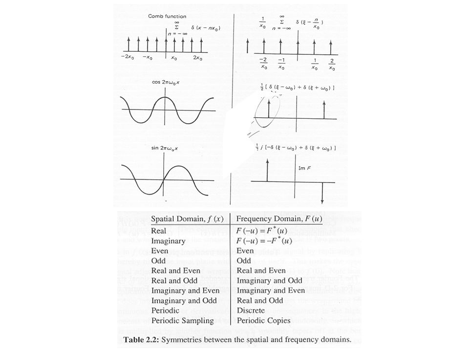
From Forsyth & Ponce Table 8.1. A variety of functions of two dimensions, and their Fourier transforms. This table can be used in two directions (with appropriate substitutions for u, v and (x, y), because the Fourier transform of the Fourier transform of a function is the function. Observant readers may suspect that the results on infite sums of δ functions contradict the linearity of Fourier transforms; by careful inspection of limits, it is possible to show that they do not. 2πi
, because the Fourier transform of the Fourier transform of a function is the function. Observant readers may suspect that the results on infite sums of δ functions contradict the linearity of Fourier transforms; by careful inspection of limits, it is possible to show that they do not. 2πi.")
24
CSc 83020 3-D Computer Vision / Ioannis Stamos Discrete 2-D Fourier Transform Fast Fourier Transform (FFT)!
!")
25
CSc 83020 3-D Computer Vision / Ioannis Stamos From Shree Nayar’s notes.

26
CSc 83020 3-D Computer Vision / Ioannis Stamos From Forsyth & Ponce. Image 1 Image 2 Log of Fourier magnitude Phase Spectrum Discussion

27
CSc 83020 3-D Computer Vision / Ioannis Stamos From Forsyth & Ponce.

28
CSc 83020 3-D Computer Vision / Ioannis Stamos

29
Figure 8.11. Left: At the top is a 256x256 pixel image showing a grid obtained by multiplying two sinusoids with linearly increasing frequency. one in x and one in y. The other images in the series are obtained by resampling by factors of two, without smoothing (i.e. the next is a 128x128, then a 64x64, etc., all scaled to the same size). Note the substantial aliasing; high spatial frequencies alias down to low spatial frequencies, and the smallest image is an extremely poor representation of the large image. Right: The magnitude of the Fourier transform of each image. displayed as a log, to compress the intensity scale. The constant component is at the center. Notice that the Fourier transform of a resampled image is obtained by scaling the Fourier transform of the original image and then tiling the plane. Interference between copies of the original Fourier transform means that we cannot recover its value at some points. this is the mechanism of aliasing. Original Image 256x256 Resampled 128x128 Resampled 64x64 Corresponding Fourier Transforms ALIASING
. Note the substantial aliasing; high spatial frequencies alias down to low spatial frequencies, and the smallest image is an extremely poor representation of the large image. Right: The magnitude of the Fourier transform of each image. displayed as a log, to compress the intensity scale. The constant component is at the center. Notice that the Fourier transform of a resampled image is obtained by scaling the Fourier transform of the original image and then tiling the plane. Interference between copies of the original Fourier transform means that we cannot recover its value at some points. this is the mechanism of aliasing. Original Image 256x256 Resampled 128x128 Resampled 64x64 Corresponding Fourier Transforms ALIASING.")
30
Figure 8.11. Left: At the top is a 256x256 pixel image showing a grid obtained by multiplying two sinusoids with linearly increasing frequency. one in x and one in y. The other images in the series are obtained by resampling by factors of two, without smoothing (i.e. the next is a 128x128, then a 64x64, etc., all scaled to the same size). Note the substantial aliasing; high spatial frequencies alias down to low spatial frequencies, and the smallest image is an extremely poor representation of the large image. Right: The magnitude of the Fourier transform of each image. displayed as a log, to compress the intensity scale. The constant component is at the center. Notice that the Fourier transform of a resampled image is obtained by scaling the Fourier transform of the original image and then tiling the plane. Interference between copies of the original Fourier transform means that we cannot recover its value at some points. this is the mechanism of aliasing. Resampled 32x32 Resampled 16x16 Corresponding Fourier Transforms ALIASING From Forsyth & Ponce
. Note the substantial aliasing; high spatial frequencies alias down to low spatial frequencies, and the smallest image is an extremely poor representation of the large image. Right: The magnitude of the Fourier transform of each image. displayed as a log, to compress the intensity scale. The constant component is at the center. Notice that the Fourier transform of a resampled image is obtained by scaling the Fourier transform of the original image and then tiling the plane. Interference between copies of the original Fourier transform means that we cannot recover its value at some points. this is the mechanism of aliasing. Resampled 32x32 Resampled 16x16 Corresponding Fourier Transforms ALIASING From Forsyth & Ponce.")
31
From Shree Nayar’s notes.

32
CSc 83020 3-D Computer Vision / Ioannis Stamos Figure 8.12. Left: Resampled versions of the image of figure 8.11, again by factors of two, but this time each image is smoothed with a Gaussian of σ one pixel before resampling.This filter is a low- pass filter, and so suppresses high spatial frequency components, reducing aliasing. Right: The effect of the low-pass filter is easily seen in these logmagnitude images; the low pass filter suppresses the high spatial frequency components so that components interfere less, to reduce aliasing. Original Image 256x256 Corresponding Fourier Transforms LOW PASS FILTERING σ=1 pixel

33
CSc 83020 3-D Computer Vision / Ioannis Stamos Figure 8.12. Left: Resampled versions of the image of figure 8.11, again by factors of two, but this time each image is smoothed with a Gaussian of σ one pixel before resampling.This filter is a low- pass filter, and so suppresses high spatial frequency components, reducing aliasing. Right: The effect of the low-pass filter is easily seen in these logmagnitude images; the low pass filter suppresses the high spatial frequency components so that components interfere less, to reduce aliasing. Corresponding Fourier Transforms LOW PASS FILTERING σ=1 pixel From Forsyth & Ponce

34
CSc 83020 3-D Computer Vision / Ioannis Stamos Figure 8.12. Left: Resampled versions of the image of figure 8.11, again by factors of two, but this time each image is smoothed with a Gaussian of σ one pixel before resampling.This filter is a low- pass filter, and so suppresses high spatial frequency components, reducing aliasing. Right: The effect of the low-pass filter is easily seen in these logmagnitude images; the low pass filter suppresses the high spatial frequency components so that components interfere less, to reduce aliasing. Original Image 256x256 Corresponding Fourier Transforms LOW PASS FILTERING Gaussian σ=2 pixels

35
CSc 83020 3-D Computer Vision / Ioannis Stamos Figure 8.12. Left: Resampled versions of the image of figure 8.11, again by factors of two, but this time each image is smoothed with a Gaussian of σ one pixel before resampling.This filter is a low- pass filter, and so suppresses high spatial frequency components, reducing aliasing. Right: The effect of the low-pass filter is easily seen in these logmagnitude images; the low pass filter suppresses the high spatial frequency components so that components interfere less, to reduce aliasing. Corresponding Fourier Transforms LOW PASS FILTERING σ=2 pixels From Forsyth & Ponce

36
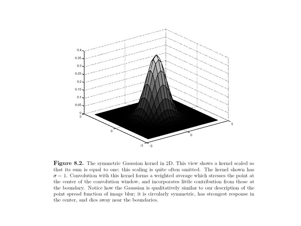
Gaussian Smoothing versus Averaging Filter mask (averaging) Filter mask (gaussian) Original image (grass) Result of averaging Result of Gaussian smoothing From Forsyth & Ponce
 Filter mask (gaussian) Original image (grass) Result of averaging Result of Gaussian smoothing From Forsyth & Ponce")
37
CSc 83020 3-D Computer Vision / Ioannis Stamos Figure 8.1. Although a uniform local average may seem to give a good blurring model, it generates effects that are not usually seen in defocussing a lens. The images above compare the effects of a uniform local average with weighted average. The image at the top shows a view of grass. On the left in the second row, the result of blurring this image using a uniform local model and on the right, the result of blurring this image using a set of Gaussian weights. The degree of blurring in each case is about the same, but the uniform average produces a set of narrow vertical and horizontal bars, an effect often known as ringing. The bottom row shows the weights used to blur the image, themselves rendered as an image; bright points represent large values and dark points represent small values (in this example the smallest values are zero).
..")
40
From Shree Nayar’s notes.

41
From Shree Nayar’s notes.

42
From Shree Nayar’s notes.

Similar presentations


>")
 Introduction to edge detection 3-D Computater Vision CSc 83020.>")


![Reminder Fourier Basis: t [0,1] nZnZ Fourier Series: Fourier Coefficient:](/16/4936498/big_thumb.jpg "Reminder Fourier Basis: t [0,1] nZnZ Fourier Series: Fourier Coefficient:>")

 all frequencies: F( ) is the spectrum of the function.>")


