Download presentation
Presentation is loading. Please wait.

1
Switching Mode Power Supply Design based on L6565 Master : Mr.Ghaderi Researcher : Dariush Moridi SMPS WwW.Dariushmoridi.blogfa.com

2
wWw.dAriushmOridi.bLOgfA.cOm

3
common EMIحذف differentials EMIحذف WwW.Dariushmoridi.blogfa.com

4
با توجه به اینکه ولتاژ ورودی متغیر می باشد. باید این تغییرات را با استفاده از این عناصر به پایه VFF انتقال داد. با تقسیم ولتاژ بین مقاومت های R8, R9,R10 همراه با مقاومت R18 ولتاژ مورد نظر به پایه ی VFF می رسد. حذف نویز TO VFF FROM MAIN LINE wWw.dAriushmOridi.bLOgfA.cOm

5
تقسیم ولتاژ نویزگیر رگولاتور شنت ( مشتق گیر) رگو تور شنت فیدبک ، برای کنترل PWM حفاظت: کنترل جریان opt coupler حذف نویز ایزو سیون در حلقه فیدبک wWw.Dariushmoridi.blogfa.cOm
 رگو تور شنت فیدبک ، برای کنترل PWM حفاظت: کنترل جریان opt coupler حذف نویز ایزو سیون در حلقه فیدبک")
6
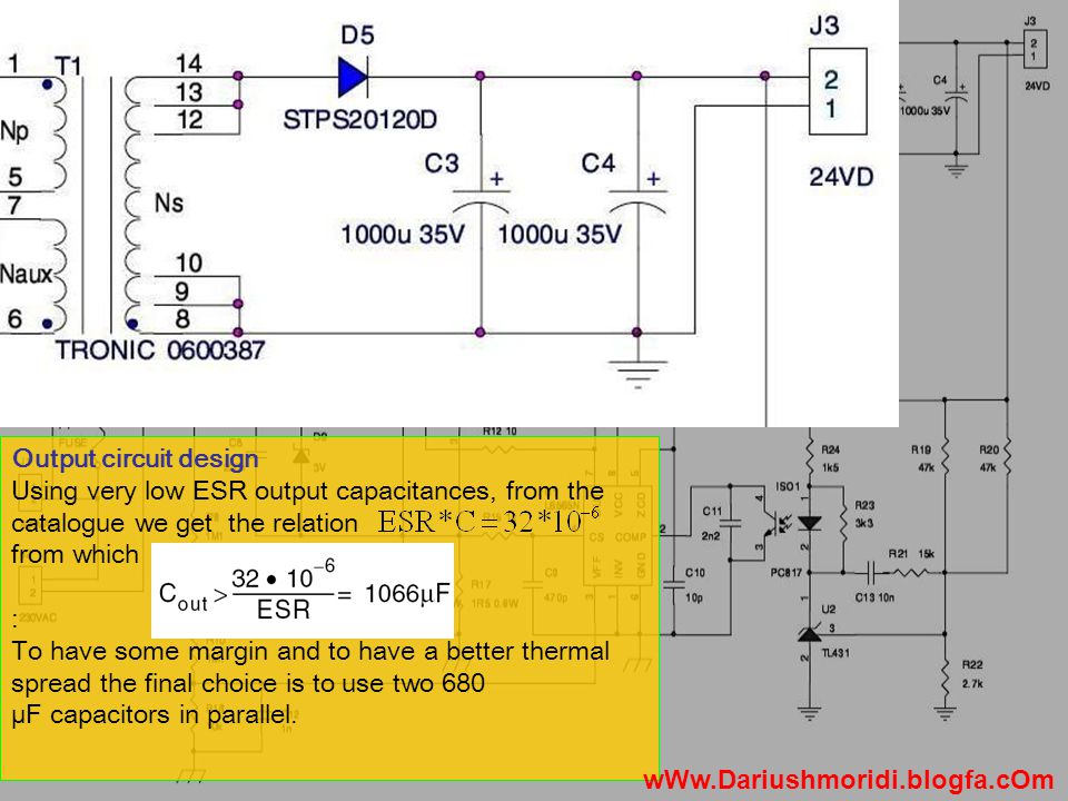
Output circuit design In order to choose the output capacitor, the series resistance of the electrolytic capacitor must be defined. It is well known that the main cause of the output ripple is the series resistance of the electrolytic capacitor, known as ESR. Electrolytic capacitor Series Resistance Secondary side Peak current wWw.Dariushmoridi.blogfa.cOm

7
Output circuit design Using very low ESR output capacitances, from the catalogue we get the relation from which : To have some margin and to have a better thermal spread the final choice is to use two 680 µF capacitors in parallel. wWw.Dariushmoridi.blogfa.cOm
8
Output circuit design با اعمال KVL در خروجی ، می توان حداکثر ولتاز روی دیود را محاسبه کرد. Finally adding a 10% margin, the STPS20120D has been selected. wWw.Dariushmoridi.blogfa.cOm

9
سیم پیچ Naux یک نمونه از ولتاژ سیم پیچ اولیه را در خود القا می کند. دیود D6 نقش یکسو سازی این ولتاژ برعهده دارد. R5 کنترل جریان و C6 نقش حذف نویز را دارد. C5 نیز بخشی از مدار Start-up می باشد. تهیه ولتاژ تغذیه L6565 To VccTo ZCD wWw.Dariushmoridi.blogfa.cOm

10
To Vcc Start-up network design To allow the circuit to start as soon as the line voltage is applied, it is necessary to precharge both C5 and C8 capacitances. مقاومت های R3, R2,R1, R4 نقش شارژ اولیه خاژن C5 را بر عهده دارند. و همچنین تعیین کننده جریانstart-up هستند. wWw.Dariushmoridi.blogfa.cOm

11
Start-up network design The current required by L6565 driver during start-up time determines the (R1+ R2+ R3+ R4) value. Considering that L6565 driver needs a 0.07mA maximum start-up current, we obtain: Start-up resistance must be lower than 3.6 M. in order to reach the best trade-off between power dissipation and time-to-start. maximum Start-Up current, wWw.Dariushmoridi.blogfa.cOm

12
Start-up network design As a consequence, before choosing start-up resistor, we have to determine C5 capacitance value, is set according to another requirement. C5 must be able to supply L6565 driver until the steady state behavior of the converter is established. Minimum Quiescent current difference between start-up threshold and under-voltage threshold

13
Start-up network design Finally we can set the start-up resistance value in order to reduce time-to-start and contemporarily optimize standby power dissipation. The L6565 has a maximum start-up threshold of 14.5 V, therefore the maximum time- to-start is approximately: A good choice is to put in series four 200 k. resistances (R1= R2= R3= R4= 200 k.), which dissipate less than 1 W standby power.
, which dissipate less than 1 W standby power..")
14
wWw.Dariushmoridi.blogfa.cOm
15
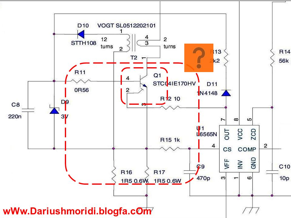
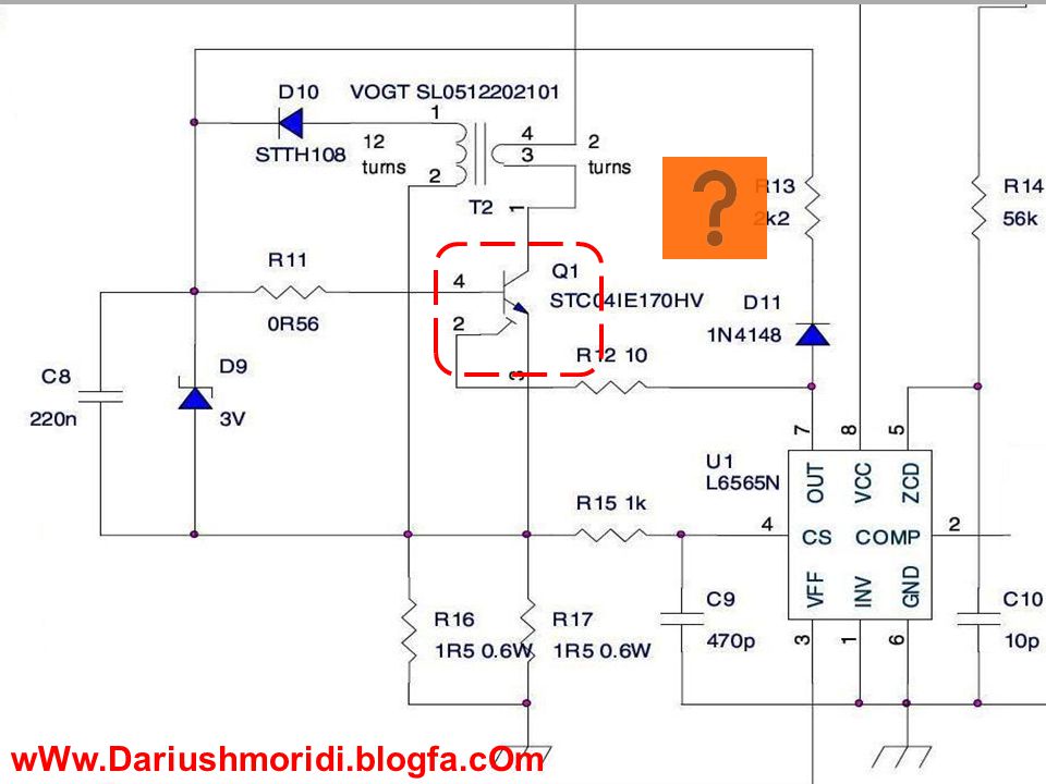
Description The STC04IE170HV is manufactured in Monolithic ESBT technology, aimed to provide the best performance in High Frequency / High voltage applications. It is designed for use in Gate Driven based topologies. Applications ■ Fly back / forward SMPS ■ Buck-bust converter wWw.Dariushmoridi.blogfa.cOm

16
Electrical ratings wWw.Dariushmoridi.blogfa.cOm

17
wWw.Dariushmoridi.blogfa.cOm
18
جلوگیری از ورود سیگنال ناخواسته به OUT The pre-charge of C8 base capacitance is made connecting it to the OUT pin of L6565 through a diode in series to a 2.2 k. resistance. حذف نویز حفاظت :کنترل جریان بیس تهیه ولتاژ بیس ( پیوسته) تهیه سیگنال برای CS ایجاد افت ولتاژ برای CS کنترل جریان CS wWw.Dariushmoridi.blogfa.cOm
 تهیه سیگنال برای CS ایجاد افت ولتاژ برای CS کنترل جریان CS")
20
L6565 SPESIFICATION LINE FEED FORWARD TO DELIVER CONSTANT POWER vs. MAINS CHANGE ULTRA-LOW START-UP (< 70µA) AND QUIESCENT CURRENT (< 3.5mA) DISABLE FUNCTION (ON/OFF CONTROL) 1% PRECISION (@ Tj = 25°C) INTERNAL REFERENCE VOLTAGE ±400mA TOTEM POLE GATE DRIVER APPLICATIONS TV/MONITOR SMPS AC-DC ADAPTERS/CHARGERS DIGITAL CONSUMER PRINTERS, FAX MACHINES, PHOTOCOPIERS AND SCANNERS wWw.Dariushmoridi.blogfa.cOm
 AND QUIESCENT CURRENT (< 3.5mA) DISABLE FUNCTION (ON/OFF CONTROL) 1% PRECISION Tj = 25°C) INTERNAL REFERENCE VOLTAGE ±400mA TOTEM POLE GATE DRIVER APPLICATIONS TV/MONITOR SMPS AC-DC ADAPTERS/CHARGERS DIGITAL CONSUMER PRINTERS, FAX MACHINES, PHOTOCOPIERS AND SCANNERS")
21
INV معکوس کننده ی error amplifierمی باشد. با ترکیب عناصر بین این پایه و پایه ی COMP می توان یک نوع شبکه فیدبک به وجود آورد. اما در این مدار از این نوع فیدبک استفاده نمی شود ( INV زمین شده). PIN DESCRIPTION wWw.Dariushmoridi.blogfa.cOm
. PIN DESCRIPTION")
22
حذف نویز ( فیلتر مولفه های فرکانس بالا)
")
23
Description&VFF CS VFF: تغییرات ولتاژ ورودی با استفاده از تقسیم ولتاژ R1 و R2 و پایه VFF به آی سی می رسد. بلوک Voltage Feed Forward ولتاژ پایه VFF را با خروجی E/A ترکیب کرده ، و یک ولتاژ مرجع را برای مقایسه کننده PWM تهیه می کند. CS: معکوس کننده ی PWM Comp می باشد. جریان عبوری از سلف را خوانده ، با استفاده از مقاومت Rs آن را به ولتاژی( که متناسب با جریانش می باشد ) تبدیل کرده ، اگر این ولتاژ بیشتر از ولتاژی باشد که Voltage Feed Forward تعیین کرده ، Pwm Latch ریست شده و خروجی صفرخواهد شد(خاموش شدن MOSFET ) اگر بیشتر از2V شود حالت Hiccup فعال شده و منجر بهDisable شدن Driver می شود.
 تبدیل کرده ، اگر این ولتاژ بیشتر از ولتاژی باشد که Voltage Feed Forward تعیین کرده ، Pwm Latch ریست شده و خروجی صفرخواهد شد(خاموش شدن MOSFET ) اگر بیشتر از2V شود حالت Hiccup فعال شده و منجر بهDisable شدن Driver می شود..")
24
ZCD Description Zero Z CD Current Detector wWw.Dariushmoridi.blogfa.cOm

26
رگولاتور ولتاژ ( تامین تغذیه کلیه قسمت های داخلی ) Under voltage Lockout :تا زمانی که ولتاژ ورودی به یک مقدار قابل اطمینان نرسد. اجازه درایو کردن را نمی دهد. حفاظت : ولتاژبا تقسیم ولتاژ

27
زمانی که خروجی Pwm Comp لچ را ریست کند ، یک پالس به Blanking می رسد. ( شروع TB ) این زمان با توجه به سیگنال پایه ی comp این زمان ادامه دارد ( خروجی صفر). با اتمام این زمان ، خروجی Blanking لچ را Set می کند. Starter : راه اندازی اولیه را به عهده دارد. ابتدا لچ را Set می کند. با Set شدن لچ متوقف می شود.
 این زمان با توجه به سیگنال پایه ی comp این زمان ادامه دارد ( خروجی صفر). با اتمام این زمان ، خروجی Blanking لچ را Set می کند. Starter : راه اندازی اولیه را به عهده دارد. ابتدا لچ را Set می کند. با Set شدن لچ متوقف می شود..")
29
Questions & Comments You Can download this project from: WwW.Dariushmoridi.blogfa.com برای دانلود جدیدترین مقالات برق الکترونیک و کامپیوتر به آدرس زیر مراجعه کنید.

30
THE END

Similar presentations


 = P(a|b)P(b)/P(a) P(b|a) = P(a|b)P(b)/P(a) این قانون برای استنتاج آماری استفاده می شود. این قانون برای استنتاج آماری استفاده.>")


 –امکان باز.>")
. 2 Private Network شبکه خصوصی شبکه ای است که بطور مستقیم به اینترنت متصل نیست در یک شبکه خصوصی آدرس های IP به دلخواه.>")

>")

 Configuration>")


 Lecturer: Reza Arjmandi Autumn 2015 Lecture 18: Introduction ADC Unit and initialization.>")
