Download presentation
Presentation is loading. Please wait.

1
2.7 Programming of Milling and Holes Operations 2.7.1 The characteristics of programming (1) The characteristics of profiles milling programming Profiles: linear profile , circular profile , and other curves , etc . Profiles are machined on a plane→ first identify this plane before any commands (2) The characteristics of hole operations Hole operations: drilling, boring, tapping and spot drilling, etc. math handling is very simple The tool pledges the diameter of the hole

2
(3) Coordinate system two coordinate systems specified at different locations: 1)Coordinate system on part drawing. 2)Coordinate system specified by the CNC. This can be achieved by programming the distance from the current position of the tool to the zero point of the coordinate system.
Coordinate system specified by the CNC. This can be achieved by programming the distance from the current position of the tool to the zero point of the coordinate system..")
3
The positional relation between these two coordinate systems :

4
(4) Main program and subprogram machining of the same pattern appears at many portions of a program, a program for the pattern is created ↓ Subprogram
 Main program and subprogram machining of the same pattern appears at many portions of a program, a program for the pattern is created ↓ Subprogram")
5
Format: M98 P_ L_; M99; e.g. Main program Subprogram O1234 O1111 N10 -----; N10 ----; N20 -----; N20 ----; N30 M98 P1111 L2; N30 ----; N40 ----; --- --- N50 ----; N80 M99; N60 M98 P1111; N70 ----; N80 ----; N90 M30;

6
(5) The functions of tool compensation tools have different tool length → length of each tool measured in advance ↓ tool length compensation: setting the difference between the length of the standard tool and the length of each tool a cutter has a radius, the center of the cutter path goes around the workpiece with the cutter radius deviated → cutter radius compensation (radius stored, the tool can be moved by cutter radius apart from the part figure)
 The functions of tool compensation tools have different tool length → length of each tool measured in advance ↓ tool length compensation: setting the difference between the length of the standard tool and the length of each tool a cutter has a radius, the center of the cutter path goes around the workpiece with the cutter radius deviated → cutter radius compensation (radius stored, the tool can be moved by cutter radius apart from the part figure)")
8
2.7.2 Programming codes for milling and holes (1) Absolute and incremental programming (G90, G91) G90 and G91 are used to command absolute or incremental command, respectively Format: G90 IP__ ; G91 IP__ ;
 Absolute and incremental programming (G90, G91) G90 and G91 are used to command absolute or incremental command, respectively Format: G90 IP__ ; G91 IP__ ;")
9
Instructions: (2) Set up coordinate system G92 –Format : G92 X_Y_Z_ ; –e.g. : G92 X200.0 Y200.0 Z200.0 ; G54 ~ G59

10
(3) Polar coordinate command (G15, G16) The end point coordinate value can be in polar coordinates (radius and angle). Both radius and angle can be absolute or incremental (G90, G91) The plus direction of the angle is counterclockwise of the selected plane first axis + direction, and the minus direction is clockwise.
 The plus direction of the angle is counterclockwise of the selected plane first axis + direction, and the minus direction is clockwise..")
12
An example of bolt hole machining in polar system : Specifying angles and a radius with absolute commands : N1 G17 G90 G16 ; N2 G81 X100.0 Y30.0 Z–20.0 R–5.0 F200.0 ; N3 Y150.0 ; N4 Y270.0 ; N5 G15 G80 ;

13
Specifying angles with incremental commands and a radius with absolute commands: N1 G17 G90 G16; N2 G81 X100.0 Y30.0 Z–20.0 R–5.0 F200.0 ; N3 G91 Y120.0 ; N4 Y120.0 ; N5 G15 G80 ;

14
(4) Scaling (G50, G51) A programmed figure can be magnified or reduced (scaling). The dimensions specified with X_, Y_, and Z_ can each be scaled up or down with the same or different rates of magnification

15
Scaling along all axes at the same rate of magnification: Scaling along each axes at a different rate of magnification (mirror image)
")
16
when a negative magnification is specified, a mirror image is applied If a negative value is set, mirror image is affected

17
O4003 ;( main program ) N10 G54 G90 G00 X0 Y0 Z100 ; N20 M03 S1000 ; N30 G00 X-20 Y10 ; N40 Z30 M08 ; N50 G01 Z16 F100 ; N30 G51 X50 Y30 P0.5 ; N40 M98 P1111 ; N50 G50 ; N60 G00 X-20 Y10 ; N70 G01 Z10 F100 ; N80 M98 P1111 ; N90 G00 Z100 ; N100 M05 ; N110 M30 ; O1111 ( subprogram ) N10 G42 G01 X0 D01 ; N20 X90 ; N30 X50 Y90 ; N40 X10 Y10 ; N50 Y-10 ; N60 G40 X-20 Y10 ; N70 G00 Z30 ; N80 M99 ;
 N10 G54 G90 G00 X0 Y0 Z100 ; N20 M03 S1000 ; N30 G00 X-20 Y10 ; N40 Z30 M08 ; N50 G01 Z16 F100 ; N30 G51 X50 Y30 P0.5 ; N40 M98 P1111 ; N50 G50 ; N60 G00 X-20 Y10 ; N70 G01 Z10 F100 ; N80 M98 P1111 ; N90 G00 Z100 ; N100 M05 ; N110 M30 ; O1111 ( subprogram ) N10 G42 G01 X0 D01 ; N20 X90 ; N30 X50 Y90 ; N40 X10 Y10 ; N50 Y-10 ; N60 G40 X-20 Y10 ; N70 G00 Z30 ; N80 M99 ;")
19
O9000 ; G00 G90 X60.0 Y60.0; G01 X100.0 F100; G01 Y100.0; Figure 2.60 Mirroring example G01 X60.0 Y60.0; M99; (Main program) N10 G00 G90; N20M98P9000; N30 G51 X50.0 Y50.0 I–1 J1; N40 M98 P9000; N50 G51 X50.0 Y50.0 I–1 J–1; N60 M98 P9000; N70 G51 X50.0 Y50.0 I1 J–1 N80 M98 P9000; N90 G50;
 N10 G00 G90; N20M98P9000; N30 G51 X50.0 Y50.0 I–1 J1; N40 M98 P9000; N50 G51 X50.0 Y50.0 I–1 J–1; N60 M98 P9000; N70 G51 X50.0 Y50.0 I1 J–1 N80 M98 P9000; N90 G50;")
20
(4) Coordinate system rotation (G68, G69) A programmed shape can be rotated. When: a workpiece placed with some angle rotated from the programmed position; there is a pattern comprising some identical shapes in the positions rotated from a shape preparing a subprogram of the shape and calling it after rotation

22
Where in the block G17 (G18 or G19): Select the plane in which contains the figure to be rotated. Α _β_ : specifies the coordinates of the center of rotation for the values specified subsequent to G68 (absolute) R_ : Angular displacement with a positive value indicates counter clockwise rotation The specified angular displacement is considered an absolute or incremental value depending on the specified G code (G90 or G91)
 R_ : Angular displacement with a positive value indicates counter clockwise rotation The specified angular displacement is considered an absolute or incremental value depending on the specified G code (G90 or G91).")
23
N1 G92 X-5000 Y-5000 G17 ; N2 G68 X7000 Y3000 R60000 ; N3 G90 G01 X0 Y0 F200 ; (G91X-5000Y5000) N4 G91 X10000 ; N5 G02 Y10000 R10000 ; N6 G03 X-10000 I-5000 J-5000 ; N7 G01 Y-10000 ; N8 G69 G90 X-5000 Y-5000 N9 M02 ;
 N4 G91 X10000 ; N5 G02 Y10000 R10000 ; N6 G03 X I-5000 J-5000 ; N7 G01 Y ; N8 G69 G90 X-5000 Y-5000 N9 M02 ;")
25
O0068 主程序 N10 G90 G17 M03 S600 ; N20 G43 Z-5.0 H02 ; N30 M98 P200 ; 加工① N40 G68 X0 Y0 P45 ; 旋转 45° N50 M98 P200; 加工② N60 G69 ; 取消旋转 N70 G68 X0 Y0 P90 ; 旋转 90° N80 M98 P200 ; 加工③ N90 G49 Z50.0 N100 G69 M05 M30 ; 取消旋转 O200 子程序(①的加工程序) N110 G41 G01 X20.0 Y-5.0 D02 F300 ; N120 Y0 ; N130 G02 X30 Y0 I5 J0 ; N140 G03 X40 Y0 I5 J0 ; N150 X20 Y0 I-10 ; N160 G01 Y-6.0 N170 G40 X0 Y0 ; N180 M99 ;
 N110 G41 G01 X20.0 Y-5.0 D02 F300 ; N120 Y0 ; N130 G02 X30 Y0 I5 J0 ; N140 G03 X40 Y0 I5 J0 ; N150 X20 Y0 I-10 ; N160 G01 Y-6.0 N170 G40 X0 Y0 ; N180 M99 ;")
26
(5) Reference position a special position where ↓ the tool is exchanged or the coordinate system is set reference position ( a fixed position, to which the tool can easily be moved by the reference position return function)
 Reference position a special position where ↓ the tool is exchanged or the coordinate system is set reference position ( a fixed position, to which the tool can easily be moved by the reference position return function)")
27
① Reference position return check (G27) function which checks whether the tool has correctly returned to the reference position : ( If correctly returned along a specified axis, the lamp for the axis goes on; if not, an alarm is displayed) Format: G27 IP__ ; (IP: Specifying the reference position (absolute/incremental command)) e.g. G27 X385.612 Y210.812 Z421.226 Note: at rapid traverse rate of each axis→ cutter compensation should be cancelled before this command

28
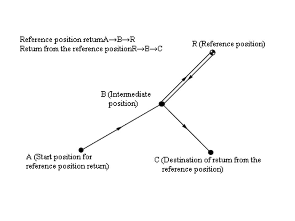
② Reference position return (G28) automatically moved to the reference position via an intermediate position along a specified axis Format: G28 IP__ ; ( IP: specifying the intermediate position (Absolute/incremental) ) e.g. G90 G54 G28 X300. Y250. ; G91 G28 X100. Y150.; G91 G28 X0 Y0; Note: the cutter compensation, and tool length compensation should be cancelled before this command.

30
③ Return from the reference position (G29) automatically move from the reference position to a specified position via an intermediate position along a specified axis (G29 is commanded immediately following the G28) Format: G29 IP__ ; ( IP: specifying the destination of return; For incremental programming, specifying the incremental value from the intermediate point )
 automatically move from the reference position to a specified position via an intermediate position along a specified axis (G29 is commanded immediately following the G28) Format: G29 IP__ ; ( IP: specifying the destination of return; For incremental programming, specifying the incremental value from the intermediate point )")
32
: M06 T02; G90 G28 Z50.0 ; M06 T03 ; G29 X35.0 Y30.0 Z5.0 ; :

33
(6) Canned cycles With a canned cycle, a frequently used machining operation can be specified in a single block ( make it easier to create programs; shorten the program to save memory )
 Canned cycles With a canned cycle, a frequently used machining operation can be specified in a single block ( make it easier to create programs; shorten the program to save memory )")
35
A canned cycle consists of a sequence of six operations Operation 1 : Positioning of axes X and Y (including also another axis) Operation 2 : Rapid traverse up to point R level Operation 3 : Hole machining Operation 4 : Operation at the bottom of a hole Operation 5 : Retraction to point R level Operation 6 : Rapid traverse up to the initial point
 Operation 2 : Rapid traverse up to point R level Operation 3 : Hole machining Operation 4 : Operation at the bottom of a hole Operation 5 : Retraction to point R level Operation 6 : Rapid traverse up to the initial point")
36
The positioning axis is an axis other than the drilling axis Travel distance along the drilling axis varies for G90 and G91

37
Return point level G98/G99 ( When the tool reaches the bottom of a hole, the tool may be returned to point R (G99) or to the initial level (G98) ( Generally, G99 is for the first drilling operation , G98 is for the last operation )
 or to the initial level (G98) ( Generally, G99 is for the first drilling operation , G98 is for the last operation )")
38
G73, G74, G76, and G81 to G89 are modal G codes → Specify all necessary drilling data at the beginning of canned cycles; when canned cycles are being performed, specify data modifications only. To repeat drilling for equally–spaced holes, specify the number of repeats in L_. ( Specify the first hole position in incremental mode (G91) ) To cancel a canned cycle, use G80
 ) To cancel a canned cycle, use G80.")
39
G81: for normal drilling (drilling, spot drilling) G81 X_ Y_ Z_ R_ F_; X_ Y_: Hole position data Z_ : Bottom data of the hole R_ : Point R level F_ : Cutting feedrate
 G81 X_ Y_ Z_ R_ F_; X_ Y_: Hole position data Z_ : Bottom data of the hole R_ : Point R level F_ : Cutting feedrate")
40
G82: for holes more accurately with respect to depth ( 沉孔,锪孔,阶梯孔) G82 X_ Y_ Z_ R_ P_ F_ ( P_ : Dwell time at the bottom of a hole ) At the bottom, a dwell is performed
 G82 X_ Y_ Z_ R_ P_ F_ ( P_ : Dwell time at the bottom of a hole ) At the bottom, a dwell is performed")
41
G85 : for reaming cutting feed is performed to return to point R G85 X_ Y_ Z_ R_ F_

42
G86: used to bore a hole the spindle is stopped at the bottom of the hole G86 X_ Y_ Z_ R_ F_

43
G76: for fine boring (When the bottom reached, the spindle stops at a fixed rotation position, and the tool is moved away from the machined surface and retracted) G76 X_ Y_ Z_ R_ Q_ P_ F_ Q_ : Shift amount at the bottom of a hole P_ : Dwell time at the bottom of a hole
 G76 X_ Y_ Z_ R_ Q_ P_ F_ Q_ : Shift amount at the bottom of a hole P_ : Dwell time at the bottom of a hole")
44
Examples

47
Example : Incremental mode for canned cycles (a series of evenly spaced holes along one direction: Program holes incrementally to drastically reduce the number of commands )
")
48
O0046; G54 T01 M06; M03 S600; G43 G00 H01 Z20.; X0. Y20. M08; G99 G91 G81 X20. Z-17. R-18. F50. L10; Y20.; (first hole in second row) X-20 L9; (nine holes in second row) Y20. (first hole in third row) X20 L9; (nine holes in third row) … G80 M09; G49 G91 G28 Z0 ; M30;
 X-20 L9; (nine holes in second row) Y20. (first hole in third row) X20 L9; (nine holes in third row) … G80 M09; G49 G91 G28 Z0 ; M30;.")
49
G73: performs high–speed peck drilling (It performs intermittent cutting feed to the bottom of a hole, while removing chips from the hole) G73 X_ Y_ Z_ R_ Q_ F_ Q_ : Depth of cut for each cutting feed, specified as an incremental value
 G73 X_ Y_ Z_ R_ Q_ F_ Q_ : Depth of cut for each cutting feed, specified as an incremental value")
50
G83: performs peck drilling (It performs intermittent cutting feed to the bottom of a hole while removing shavings from the hole) G83 X_ Y_ Z_ R_ Q_ F_
 G83 X_ Y_ Z_ R_ Q_ F_")
51
G74: performs left–handed tapping ( when the bottom of the hole has been reached, the spindle rotates clockwise) G74 X_ Y_ Z_ R_ F_ F_ : p×n (Tapping is performed by turning the spindle counterclockwise. When the bottom has been reached, the spindle is rotated clockwise for retraction→ creates a reverse thread)
.")
52
e.g. M04 S100 ; Cause the spindle to start rotating. G90 G99 G74 X300. Y–250. Z–15. R2. F150. ; Position, tapping hole 1, then return to point R. Y–550. ; Position, tapping hole 2, then return to point R. G98 Y–750. ; Position, tapping hole 3, then return to the initial level. G80 G28 G91 X0 Y0 Z0 ; Return to the reference position return M5 ; Cause the spindle to stop rotating.

53
G84: performs tapping ( when the bottom of the hole has been reached, the spindle is rotated in the reverse direction) G84 X_ Y_ Z_ R_ F_
 G84 X_ Y_ Z_ R_ F_")
54
2.7.3 Examples for Milling and Holes Operations (1) Examples for holes operations Example 1: # 1 to # 6: Drilling of a 10mm diameter hole; # 7 to # 10: Drilling of a 20mm diameter hole; # 11 to # 13: Boring of a 95mm diameter hole (depth 50 mm).
 Examples for holes operations Example 1: # 1 to # 6: Drilling of a 10mm diameter hole; # 7 to # 10: Drilling of a 20mm diameter hole; # 11 to # 13: Boring of a 95mm diameter hole (depth 50 mm).")
56
Example 2: Hole operations on a vertical center Program planning: Operations: Center drill all holes (T01: Φ3mm center drill; S: 1000rpm; F: 50mm/min) ↓ Peck drill all holes (T02: Φ8mm drill; S: 600rpm; F: 40mm/min) ↓ Tap all holes (T03: M10 Tap; S: 100rpm; F: 150mm/min)
 ↓ Peck drill all holes (T02: Φ8mm drill; S: 600rpm; F: 40mm/min) ↓ Tap all holes (T03: M10 Tap; S: 100rpm; F: 150mm/min)")
58
Example : Incremental mode for canned cycles (a series of evenly spaced holes along one direction: Program holes incrementally to drastically reduce the number of commands )
")
59
Example 3: Multiple surfaces (Holes not machined into the top surface) Φ12mm Drill (S: 600rpm; F: 40mm/min) Sequence: from high surface to low surface
 Φ12mm Drill (S: 600rpm; F: 40mm/min) Sequence: from high surface to low surface")
60
O0030; G54 T01 M06; M03 S600; G43 G00 H01 Z20.; M08; G99 G81 X20.Y35. Z-15. R2. F50.; X60. Z-30. R-13. ; G98 X100. Z-45. R-28. ; G80 M09; G49 G91 G28 Z0 ; M30;

61
毛坯为 70 ㎜ ×70 ㎜ ×18 ㎜板材,六面已粗加工过,要求数控铣出如图 2-179 所 示的槽,工件材料为 45 钢。

62
以已加工过的底面为定位基准,用通用机用平口虎钳夹紧工件前后两侧面, 虎钳固定于铣床工作台上。 每次切深为 2 ㎜ ,分二次加工完 采用 φ10 ㎜的平底立铣刀,定义为 T01 在 XOY 平面内确定以工件中心为工件原点, Z 方向以工件上表面 为工件原点,建立工件坐标系

63
O0900; 主程序 N0010 G90 G00 Z2. S800 T01 M03; N0020 X15. Y0 M08; N0030 G01 Z-2. F80; N0040 M98 P0010; 调一次子程序,槽深为 2 ㎜ N0050 G01 Z-4. F80; N0060 M98 P0010; 再调一次子程序,槽深为 4mm N0070 G00 Z2. N0080 G00 X0 Y0 Z150. M09; N0090 M02 主程序结束

64
O0010 子程序 N0010 G03 X15. Y0 I-15. J0 ; N0020 G01 X20. ; N0030 G03 X20. Y0 I-20. J0 ; N0040 G41 G01 X25. Y15. ; 左刀补铣四角倒圆的 正方形 N0050 G03 X15. Y25. I-10. J0 ; N0060 G01 X-15. ; N0070 G03 X-25. Y15. I0 J-10. ; N0080 G01 Y-15. N0090 G03 X-15. Y-25. I10. J0; N0100 G01 X15.; N0110 G03 X25. Y-15. I0 J10.; N0120 G01 Y0; N0130 G40 G01 X15. Y0; 左刀补取消 N0140 M99; 子程序结束

65
7) SUBPROGRAM If a program contains a fixed sequence or frequently repeated pattern, such a sequence or pattern can be stored as a subprogram in memory to simplify the program. A subprogram can be called from the main program. A called subprogram can also call another subprogram.

66
Subprogram call e.g.: M98 P51002 ; This command specifies ”Call the subprogram (number 1002) five times in succession.”
 five times in succession.")
67
When the main program calls a subprogram, it is regarded as a one–level subprogram call. Subprogram calls can be nested up to four levels.

69
e.g.1: 如图所示零件, Z 起始高度为 100 mm ,切削深度为 20 mm , 外轮廓切削。试编写加工程序

70
e.g.2: 加工凸台 ( 深 10 mm) 时采用不同的刀具补偿,调用子程序,完成同一位置 的加工,为其编程。 根据加工图,采用 10 立铣刀加工,刀长为 177.10 mm 。刀具补偿: D01 值为 10.50 , H01 值为 177.6 ,用于粗加工; D11 值为 10.0 , H11 值为 177.1 ,用于精加工。
 时采用不同的刀具补偿,调用子程序,完成同一位置 的加工,为其编程。 根据加工图,采用 10 立铣刀加工,刀长为 mm 。刀具补偿: D01 值为 , H01 值为 ,用于粗加工; D11 值为 10.0 , H11 值为 ,用于精加工。")
Similar presentations


![首 页 首 页 上一页 下一页 本讲内容 投影法概述三视图形成及其投影规律平面立体三视图、尺寸标注 本讲内容 复习: P25~P31 、 P84~P85 作业: P7, P8, P14[2-32(2) A3 (1:1)]](/12/3353742/big_thumb.jpg "首 页 首 页 上一页 下一页 本讲内容 投影法概述三视图形成及其投影规律平面立体三视图、尺寸标注 本讲内容 复习: P25~P31 、 P84~P85 作业: P7, P8, P14[2-32(2) A3 (1:1)]>")


