Download presentation
Presentation is loading. Please wait.

1
The Top Errors (and Misconceptions) in LED Photometry LED Specifications: the Truth, the Whole Truth and Nothing but the Truth Ing. Daniel Kalina-Gaash Lighting Design Center

2
Can We Trust LED Specifications? Many people distrust LED and SSL specifications. Why? We’ll consider how LED specifications are determined The importance of “absolute photometry” The common errors made in photometry (some are LARGE!) Understanding why CCT is a bad metric Ing. Daniel Kalina-Gaash Lighting Design Center
 Understanding why CCT is a bad metric Ing. Daniel Kalina-Gaash Lighting Design Center.")
3
In the Good Old Days..... “Relative Photometry” ruled: Fluorescent lamp output is constant regardless of what fitting it is put into Multiply lamp flux by fitting LOR to calculate flux of luminaire Photometric data formatted in units of candelas per 1000 lumens Ing. Daniel Kalina-Gaash Lighting Design Center

4
Relative photometry is no longer applicable to SSL: LED output depends upon operating temperature In turn it depends upon the thermal design of the fitting For most SSL we have to perform absolute photometry However with SSL... Ing. Daniel Kalina-Gaash Lighting Design Center

5
How Are LED Specifications Tested? LED specifications are determined under idealised laboratory conditions: short flash of current, junction temperature of 25°C An LED will typically operate at >60°C in a luminaire If you use ten 100 lumen LEDs in a luminaire, you must not expect to generate 1,000 lumens from the luminaire, you will probably get 750-800 lm in practice As LEDs get hotter: Luminous flux DECREASES CCT INCREASES CRI changes Ing. Daniel Kalina-Gaash Lighting Design Center

6
LED Output Versus Temperature Ing. Daniel Kalina-Gaash Lighting Design Center

7
Rendering Versus Temperature Ing. Daniel Kalina-Gaash Lighting Design Center

8
Do and don’t do recommendations Test the complete fitting – don’t extrapolate from rated LED flux Test the fitting after it has reached thermal equilibrium – measure “hot lumens” and not “cold lumens” Measure the CCT and CRI of the complete fitting – thermal and optical effects significantly shift the rated colour temperature and colour rendering of LEDs Ing. Daniel Kalina-Gaash Lighting Design Center

9
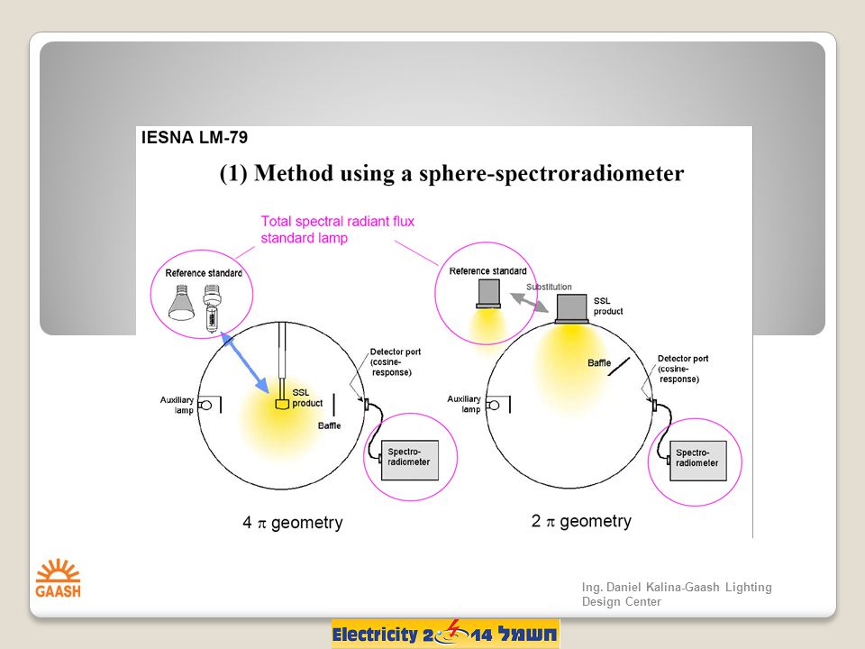
Use a high quality integrating sphere – a wooden box or other geodesic shape painted with Dulux white vinyl matt will NEVER give good results! Make sure your sphere is large enough – if you can barely squeeze the fitting inside you’ll get shadowing errors Correct for self absorption – if you don’t, you’ll probably sell yourself very short! Ing. Daniel Kalina-Gaash Lighting Design Center

10
Shadowing Effects in Spheres The perfect sphere is perfectly spherical, has no holes and is painted with a 100% reflective, perfectly Lambertian coating. The aim is to achieve a perfectly uniform luminance distribution over the surface of the sphere Ing. Daniel Kalina-Gaash Lighting Design Center

11
Low Reflectance = High Errors Recent studies have shown that low reflectance coatings introduce a significant directionality to integrating sphere readings: The lower the reflectance, the more directionally sensitive Significant errors with spotlights +15% to -22% in a sphere painted with an 80% coating Ing. Daniel Kalina-Gaash Lighting Design Center

14
Sphere Size Does Matter The perfect sphere is perfectly impossible! There is no “one-size-fits- all” policy when it comes to integrating spheres. If the light source is too big, the sphere won’t integrate properly, giving large errors. Rules of thumb: For 4 measurements of 2D/3D luminaires, sphere diameter should be 10x source size or 1.5x for linear lamps (3% surface area per IES LM79-08) For external 2 measurements, sphere diameter should be 3x source size Ing. Daniel Kalina-Gaash Lighting Design Center
 For external 2 measurements, sphere diameter should be 3x source size Ing. Daniel Kalina-Gaash Lighting Design Center.")
15
Goniophotometry & Photometric Data “Photometric Data” refers to standardised files containing the far-field luminous intensity (candelas) versus angle for a fitting: Measured using a goniophotometer Generated in.ies or.ldt formats Major sources of error include too coarse an angular sampling interval and measuring intensity in the near-field Ing. Daniel Kalina-Gaash Lighting Design Center

17
Photometric Distance Ing. Daniel Kalina-Gaash Lighting Design Center

18
Use the old 5x fitting size rule at your peril – placing the photometer at a distance of 5x the light source’s luminous aperture (e.g. 7.6m for a 5 foot fitting) was OK for extended, diffused sources but for narrow beam angle sources you could be measuring in the near-field and seeing very low candela readings Think about your scan resolution – it’s no good scanning a 15° spot with a 5° increment – you’ll only be taking 2-3 slices through the beam (beam shape will be inaccurate) Ing. Daniel Kalina-Gaash Lighting Design Center
 was OK for extended, diffused sources but for narrow beam angle sources you could be measuring in the near-field and seeing very low candela readings Think about your scan resolution – it’s no good scanning a 15° spot with a 5° increment – you’ll only be taking 2-3 slices through the beam (beam shape will be inaccurate) Ing. Daniel Kalina-Gaash Lighting Design Center.")
19
CCT is a Really Bad Metric Correlated colour temperature (CCT, Kelvin) is a simplified metric used to indicate the colour of white light produced by a lamp. The issue with CCT is that two light sources can have the same CCT but look completely different colours. The problem is down to the mathematical definition of CCT and our high sensitivity to colour difference. Ing. Daniel Kalina-Gaash Lighting Design Center

20
The Definition of CCT In 1960 CIE UCS, lines of iso-CCT fall within ± 0.02 duv Two LEDs with the same CCT can have distinctly different colours. The difference can be as much as ± 0.02 duv which is about 20 times greater than the minimum perceivable colour difference Ing. Daniel Kalina-Gaash Lighting Design Center

23
As a luminaire designer, under no circumstances should you use CCT as a purchasing metric – to stand any chance of colour matching LEDs or LED modules you have to specify colour in terms of the CIE chromaticity coordinates, Cx & Cy. And then negotiate binning tolerances with your vendor Ing. Daniel Kalina-Gaash Lighting Design Center

24
White Light from Blue - Fluorescence Differences in the thickness or optical path length through an LED phosphor can lead to significant differences in the correlated colour temperature (CCT) at different angles from the LED. When the phosphor is thinner, less blue light is converted and the CCT is higher; when it is thicker, more blue light is converted and the CCT is lower Ing. Daniel Kalina-Gaash Lighting Design Center

25
Colour Shift Through an LED Phosphor This is the colour variation from a remote phosphor LED spotlight. In the centre of the beam, the CCT is 7,500 Kelvin. At 30°, the CCT has dropped to 4,500 Kelvin. An integrating sphere measurement would only yield the average CCT. Ing. Daniel Kalina-Gaash Lighting Design Center

Similar presentations


>")
 in LED Photometry LED Specifications: the Truth, the Whole Truth.>")


