Download presentation
Presentation is loading. Please wait.

2
Common Blast Design Pitfalls Trouble Shooting The 19th Annual Surface Mined Land Reclamation Technology Transfer Seminar Jasper, Indiana December 5 th & 6 th, 2005 Wm. J. Reisz

3
Improper Hole Placement holes to close to the face optimal burdens & spacings Transient Pressures/Dynamic Shock deadpress basic blast design insufficient decking Electronic Initiation Systems why electronics? pyrotechnic demonstration Common Blast Design Pitfalls

5
Hole Placement

6
Spoil

8
Optimum Burdens & Spacings Determine Bench Parameters bench height width length hole diameter explosives type retangular 1:1.2 staggered 1:1.5

9
105’ 25’ 15’ Non-Proportional Burdens

10
105’ 105’ ÷ 4.7 = 22.3’ 82.7’ 60.4’ 38.1’ 15.8’ 105’ 16.4’ Crest burden ≈.7 X inner row burden 110’ 110’ ÷ 4.7 = 23.4’ 110’ 86.6’ 63.2’ 39.8’ 16.4’ Proportional Burdens & Spacings 153’ ÷ 6 = 25.5’ 153’ 7 holes = 6 inner hole spacings

11
Blast Design ISEE Certificate Program, Level One-Practical Blasting Fundamentals

12
Transient Pressures Deadpress Fire at a low order Total failure of the explosive charge Dynamic Shock Damage the initiator Destroy the booster Fire at the wrong time Sympathetic Detonation

13
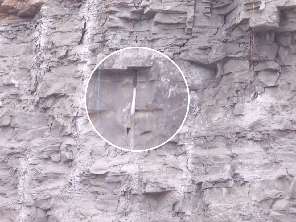
Bottom FirstInsufficient Decking

17
Bottom First Bottom Up ↔ 12 - 15 times borehole diameter For example: 9” dia. X 15 = 135” ÷ 12” = 11 ¼ ’ Stemming Between Decks Rule of Thumb

18
Top Deck First

19
Top First Top Down ↔ 1 foot for every inch of borehole diameter For example: 9” dia. X 1’ = 9’ stem Stemming Between Decks Rule of Thumb

20
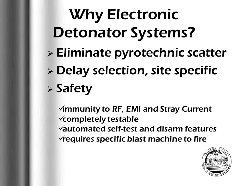
Why Electronics?

21
Why Electronic Detonator Systems? Eliminate pyrotechnic scatter poor rock fragmentation high ground vibration levels high air blast levels greater flyrock potential

27
Why Electronic Detonator Systems? Eliminate pyrotechnic scatter Delay selection, site specific Safety immunity to RF, EMI and Stray Current completely testable automated self-test and disarm features requires specific blast machine to fire

28
Eliminate pyrotechnic scatter Delay selection, site specific Safety Optimized Blast Performance Why Electronic Detonator Systems? Vibration Control Flyrock Control Floor Control Wall Control Improved Cast Percentage

29
Eliminate pyrotechnic scatter Delay selection, site specific Safety Autonomous Operation Optimized Blast Performance Inventory Control Why Electronic Detonator Systems?

30
overcome poor blast design make your job easier What Electronic Detonator Systems Will Not Do

31
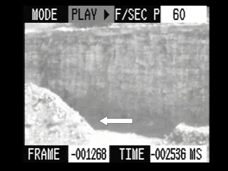
Comparison to pyrotechnic dets

32
Detonators Attached to Grade Stake Shock Tube 400 ms Daveytronic 400 ms

33
Comparison to pyrotechnic dets Daveytronic

34
Comparison to pyrotechnic dets

36
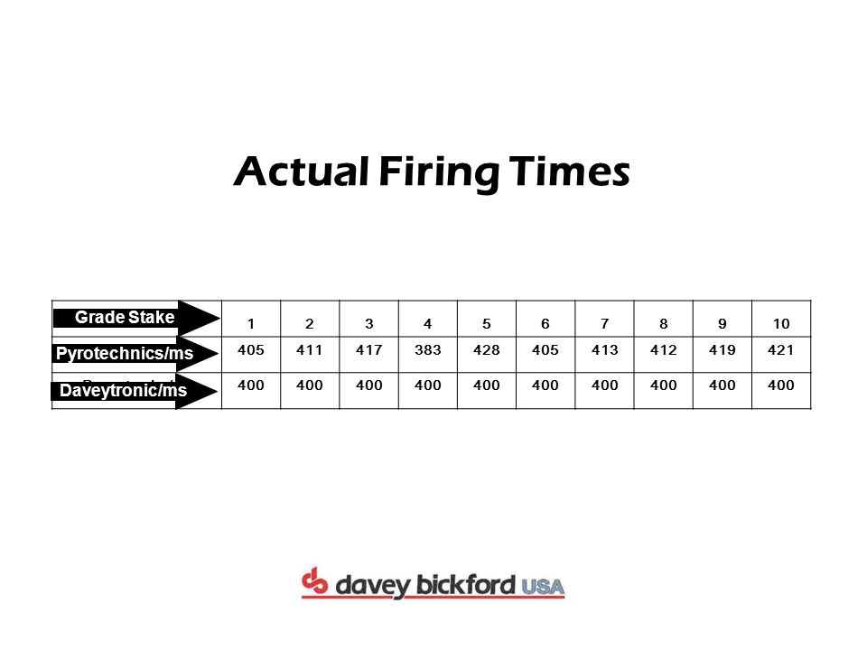
Grade Stake 12345678910 Pyrotechnics/ms405411417383428405413412419421 Daveytronics/ms400 Grade Stake Actual Firing Times Daveytronic/ms Pyrotechnics/ms

37
4110 42134 51 6885102119 136 405153 428451434 496 490 515531 555 405574 417 383428 405413 412 41917 1 2 4 3 6 5789 10 - 4.25%+ 7% Avg. dev. + 2.85% Blast Simulation Using Actual Shock Tube Firing Times Out of Sequence Holes Poor Fragmentation Zone If we add 17ms between holes we have.... Potential FlyrockHigher Air & Ground VibrationsColumn Disruption 6ms

38
Blast Design ISEE Certificate Program, Level One-Practical Blasting Fundamentals

39
Questions or Comments?

40
Thankswww.daveytronic.com Wm. J. Reisz

Similar presentations