Download presentation
Presentation is loading. Please wait.

1
Magnetic Force on a Current-Carrying Conductor
AP Physics C Montwood High School R. Casao

2
Just as a force is exerted on a single charged particle when it moves through a magnetic field, a current-carrying wire also experiences a force when placed in a magnetic field. A current consists of many charged particles in motion; the resultant force on the wire is the sum of the individual forces on the charged particles constituting the current.

3
The magnetic field B is directed out of the page.
Figure a: no current flows in the wire, so there is no force acting on the wire. Figure b: for the current I going from bottom to top, the magnetic force is directed to the right.

4
Right-hand rule: fingers of right hand in direction of the velocity of the current (bottom to top); palm faces out away from page in direction of magnetic field B; thumb points to the right. Figure c: for the current I going from top to bottom, the magnetic force is directed to the left.

5
Right-hand rule: fingers of right hand in direction of the velocity of the current (top to bottom); palm faces out away from page in direction of magnetic field B; thumb points to the left.
; palm faces out away from page in direction of magnetic field B; thumb points to the left.")
6
Consider a straight segment of wire of length l and cross-sectional area A carrying a current I in a uniform magnetic field B. The magnetic force on a charge q moving with a drift velocity vd is given by: q·v x B.

7
The force on the charge carriers is transmitted to the wire through collisions with the atoms making up the wire. The total force on the wire is found by multiplying the force on one charge by the number of charges in the segment. The volume of the segment is A·l.

8
Total magnetic force on the wire of length l: Fmag = (q·vd x B)· n·A·l
The number of charges in the segment is n·A·l, where n is the number of charges per unit volume. Total magnetic force on the wire of length l: Fmag = (q·vd x B)· n·A·l Remember that current I = n·q·vd·A. Therefore: Fmag = I·(l x B), where l is a vector in the direction of the current. The magnitude of l equals the length of the wire segment. This equation only works for a straight segment of wire in a uniform external magnetic field. The magnetic field produced by the current itself is also ignored. The wire cannot produce a force on itself.
· n·A·l. Remember that current I = n·q·vd·A. Therefore: Fmag = I·(l x B), where l is a vector in the direction of the current. The magnitude of l equals the length of the wire segment. This equation only works for a straight segment of wire in a uniform external magnetic field. The magnetic field produced by the current itself is also ignored. The wire cannot produce a force on itself.")
9
Consider a wire of uniform cross-sectional area in an external magnetic field, as shown in the figure. Dividing the wire into small segments ds that can are approximately straight, we can describe the magnetic force on a very small segment ds in the presence of a magnetic field B as:

10
dFmag is directed out of the page.
The magnetic field B can be defined as a measurable force on a current element. The force is maximum when B is perpendicular to the current element The force is zero when B is parallel to the current element. To get the total force F, integrate from one end of the wire (a) to the other end of the wire (b).
 to the other end of the wire (b).")
11
Conclusion: the magnetic force on a curved current-carrying wire in a uniform magnetic field is equal to that on a straight wire connecting the end points and carrying the same current. Case I: for a curved wire carrying a current I located in a uniform external magnetic field B.

12
The constant magnetic field B can be pulled out in front of the integral:
The quantity represents the vector sum of all the displacement elements from a to b (the length of the conductor, s). Conclusion:
. Conclusion:")
13
Case II: consider a closed loop carrying a current I placed in a uniform external magnetic field B, pull B out in front of the integral. The sum of the displacement vectors ds is zero for the closed loop because the vectors form a closed loop.

14
Since , the force Fmag = 0 N. Conclusion: the total magnetic force on any closed current loop in a uniform magnetic field is zero. Problem Example 29-2: Force on a Semicircular Conductor A wire bent into the shape of a semicircle of radius R forms a closed circuit and carries a current I. The circuit lies in the xy plane, and a uniform magnetic field is present along the positive y axis. Find the magnetic forces on the straight portion of the wire and on the curved portion.

15
Straight portion of wire:
Divide the length of the straight portion into equal elements of length ds. The angle between each equal element of length ds and the magnetic field B is 90º. Using the right hand rule and crossing ds into B indicates that the direction of the resulting magnetic force is out of the page.

16
The net force on the straight portion of the wire is the sum of the force contribution from each element of length ds. Integrating from the left end L to the right end R: L R Direction: out of the page.

17
Semicircle portion: Divide the semicircle into small elements of length ds from the right end R to the left end L. Each element of length ds is a different angle q from the vertical magnetic field B. Divide the element of length ds into a component parallel to the magnetic field B and perpendicular to the magnetic field B.

18
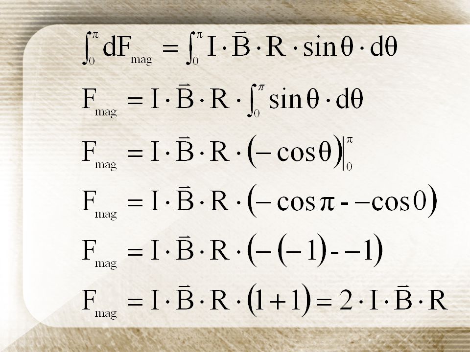
Remember that the magnetic force is zero for vector components parallel to the magnetic field and maximum for vector components perpendicular to the magnetic field. The equation for the perpendicular components is ds·sin . The angle q will vary from 0 rad to p rad for each element of length ds along the semicircular arc. arc length equation: s = R·.

19
For each element of length ds:
To get the total force on the semicircular portion, integrate from 0 rad to p rad:

21
The direction for the force on the semicircular portion of the wire is into the page.
Combine the two results. Take out of the page as the positive direction (the positive z-axis) and into the page as the negative direction (the negative z-axis). This result shows that the net force on a closed loop is 0 N.
 and into the page as the negative direction (the negative z-axis). This result shows that the net force on a closed loop is 0 N.")
22
The direction of the magnetic field due to a current carrying element is perpendicular to both the current element ds and the radius vector rhat. The right hand rule can be used to determine the direction of the magnetic field around the current carrying conductor: Thumb of the right hand in the direction of the current. Fingers of the right hand curl around the wire in the direction of the magnetic field at that point.

23
The magnetic field lines are concentric circles that surround the wire in a plane perpendicular to the wire. The magnitude of B is constant on any circle of radius a. The magnitude of the magnetic field B is proportional to the current and decreases as the distance from the wire increases.

Similar presentations


 Felix Savart (1791–1841)>")


>")


