Download presentation
Presentation is loading. Please wait.

2
Low Voltage Technology Pulse Generator Technology Lead Technology

3
Pulse Generator

4
1958, 8 October...

5
Identity ADx XL DR

6
Feed Through Telemetry Coil Sensor X-ray marker Capacitors Defib. protection Crystal

7
All bonding is doubled for safety reasons Golden Thread Welded Bonds

8
Magnet test rate 100 85 Magnet Rate <99/min: (and normal energy consumption) 6 months F-U interval Magnet Rate ~93/min: (and normal energy consumption) Replacement within 3 months Magnet Rate <85/min: Immediate replacement Elective Replacement Indicator 98.6 BOL 86.3 ERI EOL EOJ
 6 months F-U interval Magnet Rate ~93/min: (and normal energy consumption) Replacement within 3 months Magnet Rate <85/min: Immediate replacement Elective Replacement Indicator 98.6 BOL 86.3 ERI EOL EOJ")
9
Stimulation rate 63.2 65.9 67.4 69.0 70.6 64.5 EOLBOL 10203040 Battery impedance kOhms Elective Replacement Indicator

10
5 10 15 20 25 Current drain µA 0,5ms1,0ms 1,0 Volt 0,5ms1,0ms 2,5 Volt 0,5ms1,0ms 7,5 Volt Single-chamber unit, rate 60min -1 and 500Ω lead imp. Intrinsic current consumption Stimulation current consumption Exemple of current drain

11
Lead Connectors

12
IS-1 Connector in the Header

13
Tightening the Set Screw

14
Silicone rubber sealing membrane How to find the set screw

15
VS 1 IS -1 Cordis 3.2 mm VS 1B IS -1 Different 3.2 mm Short Bore Connectors

16
IS -1 Cordis 3.2 mm VS 1B IS -1 VS 1A / IS -1 VS 1B / IS -1 Different 3.2 mm Long Bore Connectors

17
VS 1B / IS -1 IS -1 Sensolog* Dialog* Sensorithm* Regency* Paragon* Synchrony* Trilogy* Affinity* Entity Integrity Identity ADx Family * Integrity µ-size Identity µ-size ADx Family µ-size Microny Not µ-size cans * Not M/S version Connectors in our Products

18
Connectors M, 5 mm S, 6 mm K, 3.2 mm (IS-1) T, 3.2 mm (IS-1) Bifurcated 3.2 mm (VDD) C, 3.2 mm inline (VDD) (for old version AddVent, obsolete now)
 T, 3.2 mm (IS-1) Bifurcated 3.2 mm (VDD) C, 3.2 mm inline (VDD) (for old version AddVent, obsolete now)")
19
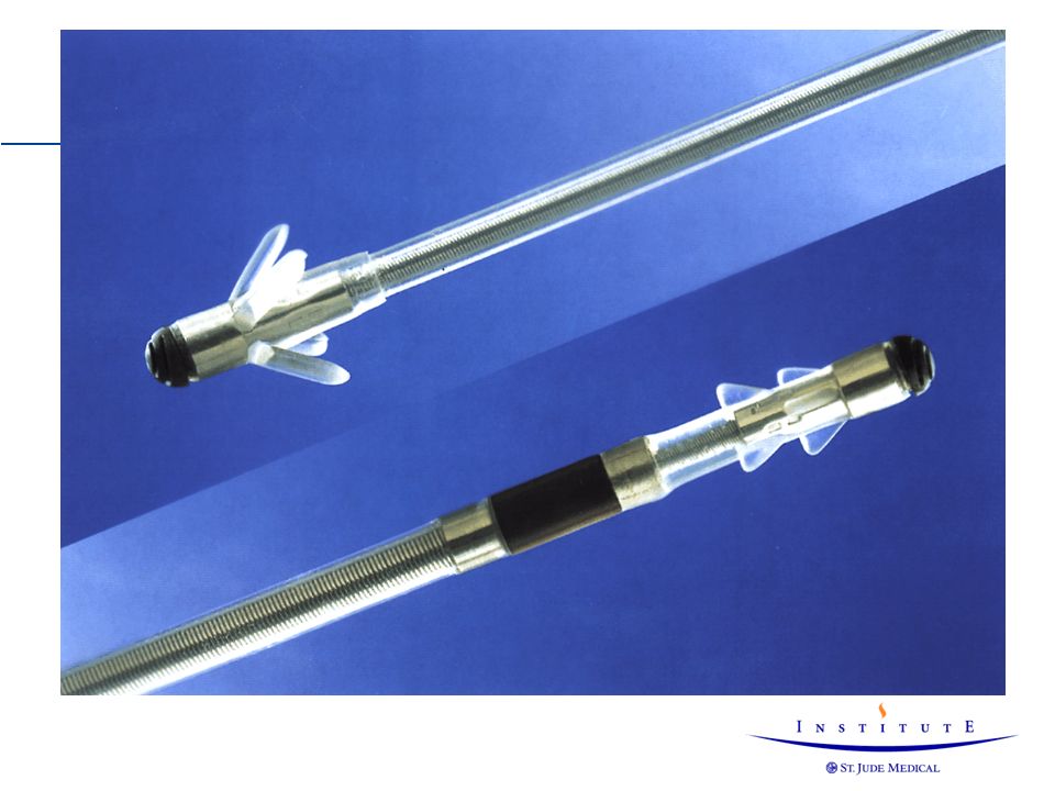
Leads

20
Endocardial Myocardial Epicardial Lead position

21
Bi-polarUni-polar Polarity configuration

22
Advantages - Bi-polar Less risk of myopotential oversensing Less risk of musclestim. Less risk of Crosstalk and Far Field Sensing Advantages - Uni-polar Smaller diameter Larger spikes on ECG With a bipolar lead, you can program the device to e.g. stimulate unipolar but sense bipolar ( ) Uni-polar or bi-polar leads?
 Uni-polar or bi-polar leads .")
23
Far-field sensing Sensing intrinsic activity in the other chamber Crosstalk Sensing pacemaker- activity in the other chamber

25
Bi-polar Uni-polar IS-1 connector

26
Coaxial Coil Design

28
Passive Active Fixation methods

29
Passive and Active Fixation

30
Myocardial lead

31
J-shaped lead (1421T)
")
32
This fractal coating creates a microscopic area ~4-600 times larger than the macro- scopic area (~15 cm 2 vs 3,2 mm 2 (Isoflex)) Titanium nitride (TiN) coating
) Titanium nitride (TiN) coating")
33
Lead position Inflammatory reaction Scar tissue Polarisation losses Insulation defects/ Conductor failure Factors affecting threshold

34
Insulation defect Conductor failure Lead defects

35
Reaction to sensing III 0=None T=Triggered I=Inhibited D=Dual (T+I) Rate Modulation IV 0=None R=Rate Modulation What is stimulated? I 0=None A=Atrium V=Ventricle D=Dual (A+V) S=Single (A or V) Multisite Pacing V 0=None A=Atrium V=Ventricle D=Dual (A+V) What is sensed? II 0=None A=Atrium V=Ventricle D=Dual (A+V) S=Single (A or V) The Revised NASPE/BPEG Generic Code for Antibradycardia, Adaptive-Rate, and Multisite Pacing, PACE, Volume 25, No. 2, February 2002 NASPE/BPEG Generic Pacemaker Code
 S=Single (A or V) Multisite Pacing V 0=None A=Atrium V=Ventricle D=Dual (A+V) What is sensed. II 0=None A=Atrium V=Ventricle D=Dual (A+V) S=Single (A or V) The Revised NASPE/BPEG Generic Code for Antibradycardia, Adaptive-Rate, and Multisite Pacing, PACE, Volume 25, No. 2, February 2002 NASPE/BPEG Generic Pacemaker Code.")
Similar presentations