Download presentation
Presentation is loading. Please wait.

1
The Geoscience Australia’s Online GPS Processing Service (AUSPOS)
Operation, Limitations and Best Practices Gary Johnston and John Dawson Geoscience Australia Earth Monitoring Group, Canberra, Australia

2
Outline GPS processing options AUSPos GPS error Sources
Principles Submitting data Reading and understanding AUSPos results GPS error Sources AUSPos recommended practices Reference frames and Datums ITRF, WGS84, GDA94 AHD, AUSGeoid98

3
GPS Processing Options
Baseline from existing geodetic infrastructure disadvantages most propriety based software has limited modeling and suits baselines < 100 km marks can be difficult to find/access requires two GPS receivers advantages not reliant on external data or processing services

4
GPS Processing Options cont.
Baseline from IGS/ARGN disadvantages user must find and download IGS/ARGN data require Internet connection need to model antennas correctly IGS/ARGN station may be > 1000km away advantages not reliant on processing services requires one GPS receiver

5
GPS Processing Options cont.
Use AUSPOS disadvantages require Internet connection requires > 6 hours of data advantages AUSPOS automatically collects IGS/ARGN data works anywhere in the world requires one GPS receiver

6
AUSPOS users submit geodetic quality GPS via web-browser
Internet web application users submit geodetic quality GPS via web-browser rapid turn-around precise positions via cm level coordinates anywhere in the world in an absolute sense position quality depends on data quantity/quality local datum within Australia (GDA94) ITRF coordinates outside of Australia FREE service
 ITRF coordinates outside of Australia. FREE service.")
7
AUSPOS Applications :- DGPS reference station positioning
Remote GPS station positioning Ultra-long GPS baseline positioning GPS connections to IGS and ARGN stations High accuracy vertical GPS positioning In the field high-accuracy processing GPS network quality control

8
AUSPOS cm level positioning with two receivers
Relative GPS Positioning cm level positioning with two receivers requires existing ground geodetic infrastructure ie. coordinated ground marks

9
AUSPOS cm level positioning with one receiver
Absolute GPS Positioning cm level positioning with one receiver geodetic infrastructure ‘invisible’ to the user

10
AUSPOS What do you Need? GPS data dual frequency data
RINEX format only > 6 hrs of continuous GPS data Internet web browser i.e. netscape, Internet Explorer address

11
AUSPOS Overview Input and Output User GPS Data Processing Results
Coordinates ( )
")
12
AUSPOS Overview What do you Submit? GPS observational data (RINEX)
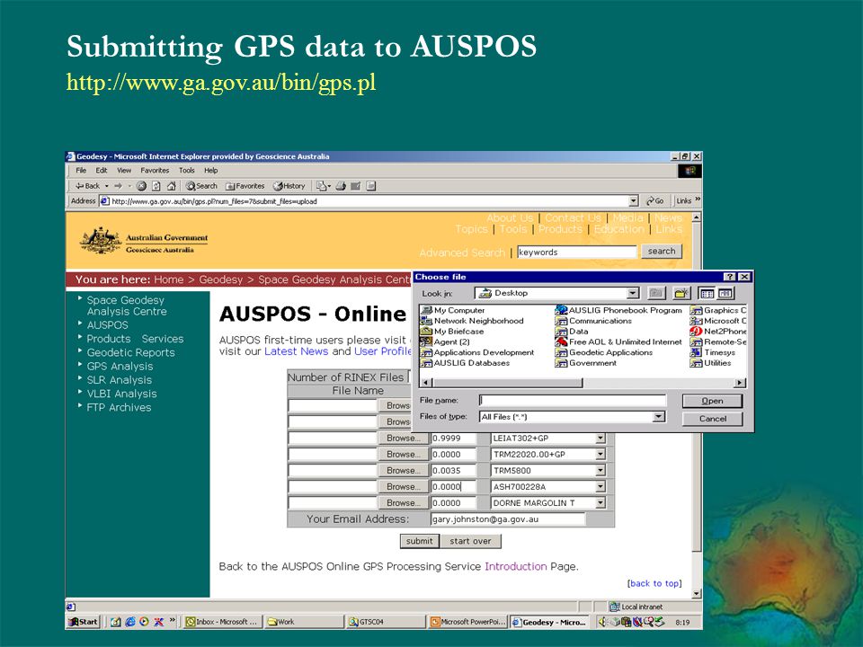
Your address the height of your GPS antenna the type of your GPS antenna What happens? Data is uploaded to GA processed results ed and available by ftp **AUSPOS Where do you submit it?

13
AUSPOS Overview Speed and accuracy 6 hour data file
results delivered in ~ 3 minutes 20 mm horizontal, 50 mm vertical 24 hour data file results delivered in ~15 minutes <10 mm horizontal and mm vertical

14
AUSPOS Overview Operations
IGS User GPS AUSPOS Overview Operations ‘invisible’ Geodetic infrastructure International GPS Service (IGS), worldwide network of permanent GPS receivers ‘baseline’ from three closest IGS GPS station to station distances typically <1000 km, up to 3500 km IGS analysis products precise orbits precise Earth Orientation Parameters
, worldwide network of permanent GPS receivers. ‘baseline’ from three closest IGS GPS. station to station distances. typically <1000 km, up to 3500 km. IGS analysis products. precise orbits. precise Earth Orientation Parameters.")
15
AUSPOS Overview Software MicroCosm
commercial version of the Goddard Space Flight Centre (GSFC) software GEODYN capable of multiple technique data processing GA currently uses MicroCosm for GPS, Satellite Laser Ranging (SLR) and DORIS Processing standards full implementation of the International Earth Rotation Service (IERS) 1996 computation standards
 software GEODYN. capable of multiple technique data processing. GA currently uses MicroCosm for GPS, Satellite Laser Ranging (SLR) and DORIS. Processing standards. full implementation of the International Earth Rotation Service (IERS) 1996 computation standards.")
16
Submitting GPS data to AUSPOS
17
AUSPOS Data Submission

18
Reading and understanding AUSPOS results

19
Reading and understanding AUSPOS results

20
Reading and understanding AUSPOS results

21
Reading and understanding AUSPOS results

22
Reading and understanding AUSPOS results

23
Reading and understanding AUSPOS results

24
GPS Processing GPS Processing Software Modelling and Error Sources
Satellite Orbits Satellite and Receiver Clock Error Tropospheric Refraction Ionospheric Refraction Antenna Phase Centre Variations Multipath

25
commonly used observation used by AUSPOS
Geodetic GPS Observations double difference observation commonly used observation used by AUSPOS GPS Baseline

26
GPS Processing Software
short baselines (< 100 km) errors sources tend to cancel in the double difference propriety processing software usually adequate long baselines (>100 km) many error sources become significant good observation modelling is essential requires sophisticated software systems E.g. MicroCosm, Bernese, Gispy, Gamit, Epos, page5
 errors sources tend to cancel in the double difference. propriety processing software usually adequate. long baselines (>100 km) many error sources become significant. good observation modelling is essential. requires sophisticated software systems. E.g. MicroCosm, Bernese, Gispy, Gamit, Epos, page5.")
27
Geodetic GPS Errors and Modelling Issues
Satellite Orbits Orbit modelling Accelerations on the satellite Solar radiation pressure other accelerations acting on GPS satellites **AUSPOS uses these IGS precise orbits

28
Geodetic GPS Errors and Modelling Issues
Satellite Orbits Orbit error example :- Precise IGS orbit versus Broadcast orbit GPS Satellite 27, 1st January 2000 Along track Cross track Radial

29
Geodetic GPS Errors and Modelling Issues
Satellite and Receiver Clock Error can be eliminated by double difference GPS receiver clock error example :- Cocos Island Receiver Clock (AOA SNR-12 ACT)
")
30
Tropospheric Refraction
troposphere is non-dispersive for GPS signals, extending to a height of about 10km both frequencies impacted identically total delay due to the troposphere is about 2.3m relative tropospheric error can impact station heights 1 cm error in troposphere signal delay produces around 3 cm error in height the troposphere can be modeled using a standard atmosphere but these models have limitations can overcome model limitations by additional parameter estimation of site specific troposphere parameters **AUSPOS estimates a tropospheric scale factor every two hours at every site used in the processing

31
Ionospheric Refraction
ionosphere is dispersive for GPS signals both frequencies impacted differently, the delay is approximately proportional to the frequency -2 GPS signal is delayed in the ionosphere due to the interaction with free electrons the total delay can vary from 1 to 20m on short baseline the ionosphere doesn’t need to be accounted for on long baseline the scale of the baseline can be impacted for the most part the impact of the ionosphere can be eliminated by combining GPS observations from both frequencies **AUSPOS uses an ionosphere corrected L1 observation

32
Modelling Earth tides example :-
Earth Tides, Suva Fiji **AUSPOS makes the IERS recommended tidal corrections

33
GPS Antenna Height and Modeling
GPS heights can now be determined very accurately accurate antenna heights are important correct antenna phase centre modeling is important incorrect identification of antenna make and model can impact the computed coordinate significantly! Up to 0.1 metre in height regardless of baseline length **AUSPOS models most commonly used antenna types which can be selected when submitting data

34
GPS Antenna Height Antenna Reference Point (ARP) - the point from which phase centre offsets are measured the Bottom of the Ground Plane (BGP) is the usual point for measuring slope heights Top of Ground Plane (TGP) is also often used Vertical Height to ARP = **AUSPOS accepts only vertical height to the ARP
 is the usual point for measuring slope heights. Top of Ground Plane (TGP) is also often used. Vertical Height to ARP = **AUSPOS accepts only vertical height to the ARP.")
35
GPS Antenna Height ARP to BGP offset Slope Height to BGP
Radius ARP to BGP offset Slope Height to BGP Vertical Height to ARP

36
GPS Antenna effects Antenna Phase Center offset
Consists of two components First is the mean offset from the Antenna Reference Point Second is the variable component around this mean Second component depends on azimuth and elevation of incoming signal Second component can cause errors in height of up to 0.1m even over very short lines IGS phase center variation models eliminate the majority of this error **AUSPOS uses the IGS models

37
Antenna constant phase center offsets examples :-
Trimble: TR GEOD L1/L2 GP (Mod , compact, with groundplane) TR GEOD L1/L2 W/O GP (Mod , compact, without groundplane) < L1/L2 / \ < TGP < BGP | | | | | | x < ARP=BPA < > NOTCHES < > EDGE Leica SR299E/SR399E: EXTERNAL WITH GP EXTERNAL WITHOUT GP / \ / \ / \ / \ < L1/L2 \ x / < ARP=TOP | > < | ===| |=== -+ +- | | Ashtech: GEODETIC III L1/L2 _____________ / \ < L1=L2 < TGP | | =| | < | | < ARP < > Antenna constant phase center offsets examples :-
 TR GEOD L1/L2 W/O GP (Mod , compact, without groundplane) < L1/L2. / + \ < TGP < BGP. | | | | | | x < ARP=BPA. < > NOTCHES. < > EDGE. Leica SR299E/SR399E: EXTERNAL WITH GP EXTERNAL WITHOUT GP. / \ / \ / \ / + \ < L1/L \ x / < ARP=TOP. | > < | ===| |=== | | Ashtech: GEODETIC III L1/L2. _____________. / \ < L1=L < TGP | | =| | < | | < ARP. < > Antenna constant phase center offsets examples :-")
38
GPS Signal Characteristics
Right Hand Circular Polarised L1 wavelength 19.05cm L2 wavelength cm receipt characteristic depend on signal azimuth and elevation, as well antenna element

39
Phase Center Offset Diagram (ASHTECH)
")
40
Phase Center Offset Diagram (DMT)
")
41
Effect of Phase Center Variations

42
Effect of Phase Center Variations

43
Impact of Phase variations, example :-
May 1995 NTF campaign with geodetic quality GPS equipment differences between solution that has no variable model applied and solutions that have IGS phase models applied difference shows very little effect in horizontal position. vertical difference varies from one antenna type to another, and one location to another Differences are generally the same for like antennae in close proximity to each other

44
Impact of Phase variations, example :-

45
Multipath systematic biases can result up to 20 m in pseudorange
multipath is the result of GPS signals that are reflected from a surface near to the antenna. The GPS antenna receives both the direct and indirect signal systematic biases can result up to 20 m in pseudorange up to several centimeters in the carrier phase measurements multipath effects greater for low elevation satellites multipath is difficult to model because it depends on the antenna environment **AUSPOS tip -- when observing GPS take care to avoid high multipath environments

46
AUSPos recommended practices
Positional Uncertainty (m) 1 (Horiz Vert) Location 2 Australia IGS products 3 (minimum standard accepted) IGS Final (~14 day delay) IGS Rapid (~2 Delay) IGS Ultra-rapid (partly predicted) GPS Receiver 4 Geodetic, dual frequency, carrier phase & code GPS Antenna 5 IGS/NGS modelled GPS data format 6 RINEX GPS data sampling 7 30 sec Duration of observations 8 Multiple 24 hour sessions Multiple 6 hour sessions Multiple 2 hour sessions Repeatability between sessions (m) 9 Transformation to GDA94 10 Yes Solution statistics satisfied 11 Antenna type 12 Make, model & serial number Antenna height 13 mm Reference stations 14 At least 3 within 1500 km At least 3 Positional Uncertainty versus GPS data attributes for “absolute” positioning.
 1 (Horiz Vert) Location 2. Australia. IGS products 3 (minimum standard accepted) IGS Final. (~14 day delay) IGS Rapid. (~2 Delay) IGS Ultra-rapid. (partly predicted) GPS Receiver 4. Geodetic, dual frequency, carrier phase & code. GPS Antenna 5. IGS/NGS modelled. GPS data format 6. RINEX. GPS data sampling sec. Duration of observations 8. Multiple 24 hour sessions. Multiple 6 hour sessions. Multiple 2 hour sessions. Repeatability between sessions (m) 9. Transformation to GDA Yes. Solution statistics satisfied 11. Antenna type 12. Make, model & serial number. Antenna height 13. mm. Reference stations 14. At least 3 within 1500 km. At least 3. Positional Uncertainty versus GPS data attributes for absolute positioning.")
47
AUSPos guidelines Positional Uncertainty is a 95% confidence value, in metres, with respect to the GDA94. Outside Australia results are ITRF at the epoch of the survey. Refer to the IGS product guidelines at Some hand-held receivers may provide phase & code, but the quality of their data cannot be guaranteed for this type of processing

48
AUSPos Guidelines Must apply antenna phase centre variation
Receiver Independent EXchange format (RINEX) is required Most processes use 30 second data, but will accept any sampling rate less than 30 seconds that can be stripped back to 30 seconds (e.g. 1, 3, 5, 6, 10, 15, 30 sec). Each session should be entirely within a UT day. Repeat shorter duration sessions should be observed at different times of the UT day to minimise systematic effects from the GPS system and ambient site conditions (e.g. similar satellite constellation). Multiple sessions are recommended to ensure repeatability and hence confidence in the result. Re setup equipment for each session
 is required. Most processes use 30 second data, but will accept any sampling rate less than 30 seconds that can be stripped back to 30 seconds (e.g. 1, 3, 5, 6, 10, 15, 30 sec). Each session should be entirely within a UT day. Repeat shorter duration sessions should be observed at different times of the UT day to minimise systematic effects from the GPS system and ambient site conditions (e.g. similar satellite constellation). Multiple sessions are recommended to ensure repeatability and hence confidence in the result. Re setup equipment for each session.")
49
AUSPos guidelines Transformation to the GDA94 is required. The time-varying ITRF-GDA94 transformation parameters published by Geoscience Australia are recommended Must examine coordinate precisions and observation fits to ensure acceptability The calibration for an antenna can be different, even for the same brand with only slight variations in the model. Exact identification is essential to ensure that the correct calibration is applied (see note 5). Ensure correct antenna heights used Check operation of nearest 3 ARGN stations for critical
. Ensure correct antenna heights used. Check operation of nearest 3 ARGN stations for critical.")
50
Reference Frames and Datums
The International Terrestrial Reference Frame (ITRF) ITRF Definition ITRF History Relationships to the IGS realisation of the ITRF The World Geodetic System 1984 (WGS84) The Geocentric Datum of Australia (GDA) The relationship between ITRF, WGS84 and GDA GPS heighting issues
 ITRF Definition. ITRF History. Relationships to the IGS realisation of the ITRF. The World Geodetic System 1984 (WGS84) The Geocentric Datum of Australia (GDA) The relationship between ITRF, WGS84 and GDA. GPS heighting issues.")
51
Reference Frames and Datums
International Terrestrial Reference Frame (ITRF) What is the ITRF? precise station coordinates and velocities globally consistent Internationally accepted reference frame ideal for geodetic applications History ITRF92, ITRF93, ITRF94, ITRF96, ITRF97 ITRF2000 (current) ITRF2000 Primary + Densification
 What is the ITRF precise station coordinates and velocities. globally consistent. Internationally accepted reference frame. ideal for geodetic applications. History. ITRF92, ITRF93, ITRF94, ITRF96, ITRF97. ITRF2000 (current) ITRF2000 Primary + Densification.")
52
Reference Frames and Datum
How is the ITRF Primary Solution Computed? analysis groups submit their solutions combined by the International Earth Rotation Service (IERS) includes data back to 1977 Solutions 3 x Very Long Baseline Interferometry (VLBI) 1 x Lunar Laser Ranging (LLR) 7 x Satellite Laser Ranging (SLR) 6 x Global Positioning System (GPS) 2 x Doppler Orbitography and Radio Positioning Integrated by Satellite (DORIS) 2 x multi-technique solutions Local Ties between techniques
 includes data back to Solutions. 3 x Very Long Baseline Interferometry (VLBI) 1 x Lunar Laser Ranging (LLR) 7 x Satellite Laser Ranging (SLR) 6 x Global Positioning System (GPS) 2 x Doppler Orbitography and Radio Positioning Integrated by Satellite (DORIS) 2 x multi-technique solutions. Local Ties between techniques.")
53
Very Long Baseline Interferometry
VLBI uses observations of quasars observables from telescopes involved in simultaneous measurements are correlated to produce an experiment microwave frequency band ~30 stations with global coverage

54
Lunar/Satellite Laser Ranging
LLR and SLR simple measure of time of flight of a laser pulse ~ 30 SLR stations global coverage (but biased to northern hemisphere) ~ 60 satellite and lunar targets canonball geodetic satellites lageos1/2 ~9000 km altitude
 ~ 60 satellite and lunar targets. canonball geodetic satellites. lageos1/2 ~9000 km altitude.")
55
Global Positioning System
GPS dual frequency interferometry ~ 200 permanent IGS stations global coverage (receive) ~27 satellites ~20,000 km altitude (transmit)
 ~27 satellites ~20,000 km altitude (transmit)")
56
Doppler Orbitography & Radio Positioning Integrated by Satellite
DORIS dual frequency doppler ~ 51 stations with global coverage (transmit) ~ 5 satellites (receive) SPOT2 satellite ~7000 km altitude developed for precise orbit determination of low orbiting satellites significant tool for high precision global geodesy
 ~ 5 satellites (receive) SPOT2 satellite ~7000 km altitude. developed for precise orbit determination of low orbiting satellites. significant tool for high precision global geodesy.")
57
Reference Frames and Datum
ITRF2000 GPS, SLR, DORIS, VLBI Network, Pacific

58
ITRF2000 Scale and rate weighted average of the VLBI and SLR solutions
Origin (translations and rates) weighted average of the SLR solutions Rotations ITRF97 at epoch rates No Net Rotation w.r.t NNR-NUVEL1A Core Network Stations continuously observing over 3 years located away from plate boundaries and deforming zones velocity accuracy better than 3 mm/yr velocity residuals > 3 mm/yr < 2 solutions
 weighted average of the SLR solutions. Rotations. ITRF97 at epoch. rates No Net Rotation w.r.t NNR-NUVEL1A. Core Network Stations. continuously observing over 3 years. located away from plate boundaries and deforming zones. velocity accuracy better than 3 mm/yr. velocity residuals > 3 mm/yr < 2 solutions.")
59
WGS84 United States Department of Defense
origin is the Earth’s centre of mass WGS84 ellipsoid semi-major axis flattening 1/ refined WGS84 (G730) ITRF91 29 June 1994 WGS84 (G873) coordinates re-computed 29 January 1997 Now mapped to align with ITRF
 ITRF June WGS84 (G873) coordinates re-computed. 29 January Now mapped to align with ITRF.")
60
The Geocentric Datum of Australia
ITRF92 fixed at epoch realised by the positions of the ARGN stations within Australia (Australian Fiducial Network) GRS80 ellipsoid Transformation parameters exist to convert to GDA94
 GRS80 ellipsoid. Transformation parameters exist to convert to GDA94.")
61
Relationship between ITRF, WGS84 and GDA
ITRF versus GDA tectonic motion re-computation of ITRF solutions ITRF/GDA versus WGS84 WGS84 difficult to realise precisely practically equivalent **AUSPOS provides both ITRF and GDA coordinates by using an GA transformation process

62
Relationship between geoid & ellipsoid
AHD MSL N is the geoid-ellipsoid separation In an absolute sense H = h - N where: H = height above the geoid h = height above the ellipsoid N = Geoid-Ellipsoid separation

63
Brief history of the Australian Height Datum (AHD)
Mainland basic network (5 May 71) 30 tide gauges MSL epoch Predominantly 3rd order observations Tasmanian basic network (17 Oct 83) 2 tide gauges MSL epoch 1972 3rd order observations Supplementary networks On-going network upgrades Latest geoid AUSGeoid98
 30 tide gauges MSL epoch Predominantly 3rd order observations. Tasmanian basic network (17 Oct 83) 2 tide gauges MSL epoch rd order observations. Supplementary networks. On-going network upgrades. Latest geoid AUSGeoid98.")
64
Australian Height Datum Basic Network
AHD tide gauge NTF ABSLMA tide gauge

65
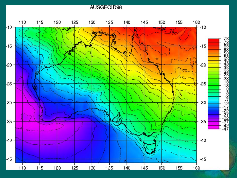
AUSGeoid98 AUSGeoid98 computed using :-
EGM96 global geopotential model GRS80 ellipsoid 1996 Australian Gravity data base from AGSO GEODATA 9” DEM Satellite altimeter-derived free-air gravity anomalies offshore

67
AUSGeoid98 :- Validation data set consisted of 906 points with AHD and GPS heights Standard deviation of 36cm resulted relative accuracy at 3rd order or better validation points usually used older GPS and AHD spurs

68
AHD tide gauge GPS survey :-
ICSM agencies 1999/2000 Geodetic GPS receivers 5 day continuous observations AHD tide gauge BM or suitable nearby BM Included some NTF ABSLMA sites GPS data set compiled by GA Junction Point Survey 2000 – present > 200 AHD junctions points ITRF2000 ellipsoidal heights observed

69
GPS Points used for Height Modernisation

70
AHD(constrained to Geoid - AHD(new)
")
71
Adjustment comparison AHD(new) - AHD71
AHD71 does not reproduce. Updates and corrections to AHD since 1971. s.d.= 0.061m Min resid = m Max resid =0.364m

72
Avoiding the errors :- The use of Ausgeoid98 in a relative sense will produce 3rd order AHD heights Use AUSPOS on a known AHD benchmark to determine the geometric N value then use the difference in N from the WINTER software to transfer the AHD height

73
Geodetic GPS infrastructure
Permanent GPS Networks International GPS Service (IGS) IGS Data and Products IGS GPS data IGS precise orbits and Earth orientation parameters Accessing IGS Data and Products The Australian Regional GPS Network (ARGN) ARGN Data and Products Accessing ARGN Data and Products
 IGS Data and Products. IGS GPS data. IGS precise orbits and Earth orientation parameters. Accessing IGS Data and Products. The Australian Regional GPS Network (ARGN) ARGN Data and Products. Accessing ARGN Data and Products.")
74
Permanent GPS Networks
International GPS Service (IGS) Permanent GPS 200+ Dual frequency GPS operated national agencies, research organisations, universities,… Permanently tracking Dorne Margolin Type antenna + domes in some cases 30 second interval RINEX freely available IGS related information
 Permanent GPS Dual frequency GPS. operated national agencies, research organisations, universities,… Permanently tracking. Dorne Margolin Type antenna. + domes in some cases. 30 second interval RINEX. freely available. IGS related information.")
75
International GPS Service (IGS) Permanent GPS
 Permanent GPS")
76
International GPS Service (IGS) Permanent GPS
IGS Products precise orbits precise Earth Orientation (Earth Pole Position) precise coordinate of IGS stations Accessing IGS products :- ftp://igscb.jpl.nasa.gov/igscb/product/XXXX where XXXX is the GPS week GPS week 0 starts Sunday 6 January 1980 GPS week 1124 starts Sunday 22 July 2001
 precise coordinate of IGS stations. Accessing IGS products :- ftp://igscb.jpl.nasa.gov/igscb/product/XXXX. where XXXX is the GPS week. GPS week 0 starts Sunday 6 January GPS week 1124 starts Sunday 22 July")
77
Accessing ARGN RINEX data
ftp ftp.ga.gov.au/gpsdata/yyddd anonymous login RINEX data UNIX compressed where yy is the year and ddd is the day of year Accessing IGS RINEX data ftp cddisa.gsfc.nasa.gov/gps/gpsdata/yyddd/yyo

78
Australian Regional GPS Network (ARGN)
15 Dual frequency GPS operated by GA Permanently tracking Dorne Margolin Type antenna + domes in some cases 30 second interval RINEX freely available all data contributed to the IGS major applications primary geodetic infrastructure geosciences atmospheric science GPS precise orbit determination

79
Australian Regional GPS Network (ARGN)
")
80
Geodetic GPS Data Geodetic GPS Observations GPS Data formats
Propriety data formats The RINEX data format Propriety data formats translation Translation options TEQC TEQC translation TEQC Quality checking

81
AUSPOS requires L1 and L2 carrier phase observation
some pseudorange observations are also needed GPS Data Formats GPS providers each support their own data format these formats are generally binary often format details are difficult to obtain or considered commercial in confidence RINEX Data Format "Receiver Independent Exchange Format" or RINEX has been developed by the Astronomical Institute of the University of Berne for the easy exchange of the GPS data International standard ASCII format ftp://igscb.jpl.nasa.gov/igscb/data/format/rinex210.txt **AUSPOS only accepts RINEX data

82
RINEX Data Format 2.00 OBSERVATION DATA G (GPS) RINEX VERSION / TYPE
teqc 2000Jul :28:34UTCPGM / RUN BY / DATE Solaris 2.7|Ultra 2|cc SC5.0|=+-|*Sparc COMMENT RGRINEXO V2.5.5 UX AUSLIG JAN- 0 12: COMMENT Australian Regional GPS Network (ARGN) COMMENT ALICE SPRINGS AU COMMENT HARDWARE CALIBRATION (S) COMMENT CLOCK OFFSET (S) COMMENT BIT 2 OF LLI (+4) FLAGS DATA COLLECTED UNDER "AS" CONDITION COMMENT ALIC MARKER NAME 50137M MARKER NUMBER auslig auslig OBSERVER / AGENCY C126U AOA ICS-4000Z ACT / REC # / TYPE / VERS AOAD/M_T DOME ANT # / TYPE APPROX POSITION XYZ ANTENNA: DELTA H/E/N WAVELENGTH FACT L1/2 4 L1 L2 P1 P # / TYPES OF OBSERV INTERVAL teqc windowed: 2001 Jan 1 00:00: COMMENT teqc windowed: delta = sec COMMENT GPS TIME OF FIRST OBS END OF HEADER G14G17G15G26G28G23G30G 6G22G21 G14G17G15G26G28G23G30G 6G22G21
 COMMENT. ALICE SPRINGS AU012 COMMENT HARDWARE CALIBRATION (S) COMMENT CLOCK OFFSET (S) COMMENT. BIT 2 OF LLI (+4) FLAGS DATA COLLECTED UNDER AS CONDITION COMMENT. ALIC MARKER NAME M001 MARKER NUMBER. auslig auslig OBSERVER / AGENCY. C126U AOA ICS-4000Z ACT / REC # / TYPE / VERS. 318 AOAD/M_T DOME ANT # / TYPE APPROX POSITION XYZ ANTENNA: DELTA H/E/N. 1 1 WAVELENGTH FACT L1/2. 4 L1 L2 P1 P2 # / TYPES OF OBSERV INTERVAL. teqc windowed: 2001 Jan 1 00:00: COMMENT. teqc windowed: delta = sec COMMENT GPS TIME OF FIRST OBS. END OF HEADER G14G17G15G26G28G23G30G 6G22G G14G17G15G26G28G23G30G 6G22G")
83
RINEX Data Format L1, L2: Phase measurements on L1 and L2 C1 : Pseudorange using C/A-Code on L1 P1, P2: Pseudorange using P-Code on L1,L2 D1, D2: Doppler frequency on L1 and L2 T1, T2: Transit Integrated Doppler on 150 (T1) and 400 MHz (T2) S1, S2: Raw signal strengths or SNR values as given by the receiver for the L1,L2 phase observations
 and 400 MHz (T2) S1, S2: Raw signal strengths or SNR. values as given by the receiver. for the L1,L2 phase observations.")
84
Propriety data formats translation
RINEX translators freely available TEQC (UNAVCO ) BERN JPL ASHTECH Source
 BERN. JPL. ASHTECH. Source.")
85
TEQC Translation example :-
fbar.bin contains the the time-sequential, real-time binary data records for GPS week 866, 11 Aug Aug 1996 from a Trimble SSE receiver. Then, execute teqc -tr so -week 866 fbar.bin > fbar o Quality checking example :- teqc +qc BASE100a.01o results available in BASE100a.01S multipath cycle slips ionosphere

86
AUSPOS Modeling IERS96 conventions orbit error
state-of-the-art processing system (MicroCosm) IERS96 conventions orbit error uses IGS precise orbits receiver and satellite clock error eliminated by double difference troposphere refraction scale factor estimated ionospheric refraction dual frequency observations Antenna phase centre variations uses IGS phase centre models Reference frame holds IGS station coordinates fixed at their IGS values (ITRF)
 IERS96 conventions. orbit error. uses IGS precise orbits. receiver and satellite clock error. eliminated by double difference. troposphere refraction. scale factor estimated. ionospheric refraction. dual frequency observations. Antenna phase centre variations. uses IGS phase centre models. Reference frame. holds IGS station coordinates fixed at their IGS values (ITRF)")
87
AUSPOS Web Pages Step by step user guide GA Geodesy home
Step by step user guide

88
AUSPOS Web Pages Frequently asked questions

89
Trouble shooting Contact Geoff Luton Telephone 02 6249 9050 Email
Contact Geoff Luton Telephone Firewall some users have firewall problems at their end so use the FTP option if the UPLOAD doesn’t work if you don’t have an ftp server you can use the GA server :- Contact Geoff Luton

90
Internet Resources Geoscience Australia home page www.ga.gov.au
IGS home page igscb.jpl.nasa.gov NGS Antenna Calibrations CDDIS Data Information System

Similar presentations

>")
 John Manning Gary Johnston Paul Digney.>")


 & Geographic Information Systems (GIS) RESOURCE INVENTORY Soil Survey National Resources Inventory (NRI) Wetlands.>")


 work>")

 System Richard Snay NOAA’s National Geodetic Survey Corbin, Virginia June 2008.>")