Download presentation
Presentation is loading. Please wait.

1
Introduction to Imaging
Patrick Knott, PhD, PA-C Physician Assistant Department

2
History of Imaging Wilhelm Konrad Roentgen discovered the x-ray in 1895 Using a cathode-ray tube, passed a current through the tube and noted a black line across a piece of platinocyanide paper laying on his workbench He termed this new invisible ray x-ray (x = unknown) Received 1st Nobel prize in physics in 1901 Widespread use for medical imaging by 1913
 Received 1st Nobel prize in physics in Widespread use for medical imaging by")
3
History of Imaging The first radiation fatality was Clarence Daley (Thomas Edison’s assistant) in 1904 Fluoroscopy was developed by Thomas Edison Ultrasound was first used in the 1940s but was used for accredited medical purposes in the 1950s Computed tomography was introduced in 1971 Magnetic resonance imaging (MRI) 1980s
 1980s.")
4
Ionizing vs Non-Ionizing Radiation
No known genetic damage Modalities Ultrasound MRI Ionizing radiation Ionizes tissue Causes genetic damage Modalities Conventional (plain-films) radiographs Fluoroscopy CT scans Nuclear imaging modalities
 radiographs. Fluoroscopy. CT scans. Nuclear imaging modalities.")
5
Ionizing Radiation Effect of ionizing radiation
Radiation protection was instituted in the 1930s Radiation absorption dose (RAD) The amount of radiation your body was exposed to Radiation effect in man (REM) The amount of biological damage received from the exposed radiation
 The amount of radiation your body was exposed to. Radiation effect in man (REM) The amount of biological damage received from the exposed radiation.")
6
Lethal dose of radiation exposure
5000 RADs to entire body kills 50% of humans Partial body exposure can cause organ atrophy and dysfunction High doses can cause hematologic effects that take months to recover from Prolonged repeated exposure leads to an accelerated induction of malignant disease

7
Radiation Exposure Exam mrads Chest Abdomen Cervical spine LS spine series Pelvis CT scan mrads/slice

8
Maximum permissible exposure
Lifetime permissible dose: (RADS) = 5 x (age - 18) Health care workers Whole body/gonads/eye lens 5 RADs/yr (5,000 mrads) Hands/forearms/feet RADs/yr (5000 / 12 = 400mrads/month = 1 lumbar spine x-ray)
 = 5 x (age - 18) Health care workers. Whole body/gonads/eye lens 5 RADs/yr (5,000 mrads) Hands/forearms/feet 75 RADs/yr. (5000 / 12 = 400mrads/month = 1 lumbar spine x-ray)")
9
Ways to reduce patient exposure to ionizing rays
Eliminate unnecessary radiographs and projections Shield the most radiation sensitive areas (gonads, eye lens, thyroid) Reduce area irradiated Avoid x-rays in pregnancy
 Reduce area irradiated. Avoid x-rays in pregnancy.")
10
Ways to reduce staff radiation exposure
Reduce exposure time Increase distance from radiation Use proper shielding Wear radiation film badge is exposed to multiple x-rays

12
How x-rays are generated
An anode (tungsten or molybdenum) is bombarded with electrons from a cathode X-rays pass through the pt and expose the film Problems X-rays are slower than light in developing film Long exposure to x-rays is needed (harmful)
 is bombarded with electrons from a cathode. X-rays pass through the pt and expose the film. Problems. X-rays are slower than light in developing film. Long exposure to x-rays is needed (harmful)")
16
Film developing A light-proof case containing a sheet of film
Film is surrounded on each side by a fluorescent sheet Brief exposure by x-rays causes the fluorescent sheets to glow Fluorescent sheets expose the film

19
Radiographic appearance is determined by:
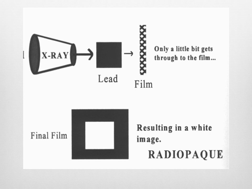
Atomic number (density) Thickness Overlap of structure (increase thickness) Object’s shape Distance from film (magnification principle) Film turns black if x-rays completely penetrate the subject and reach the film (oxidizes the silver) Film remains white if x-rays are blocked (by bone) from penetrating the subject Film is various shades of gray, depending on how many x-rays reach a film through semi-solid structures
 Thickness. Overlap of structure (increase thickness) Object’s shape. Distance from film (magnification principle) Film turns black if x-rays completely penetrate the subject and reach the film (oxidizes the silver) Film remains white if x-rays are blocked (by bone) from penetrating the subject. Film is various shades of gray, depending on how many x-rays reach a film through semi-solid structures.")
20
Radiographic Densities
Air density (most dark, radio-lucent) Fat density Soft tissue/fluid density Bone density Non-physiologic density (white, radio-opaque) Contrast agents (iodine, barium) & metals
 Fat density. Soft tissue/fluid density. Bone density. Non-physiologic density (white, radio-opaque) Contrast agents (iodine, barium) & metals.")
24
Radiographs are “Summation Shadowgrams”
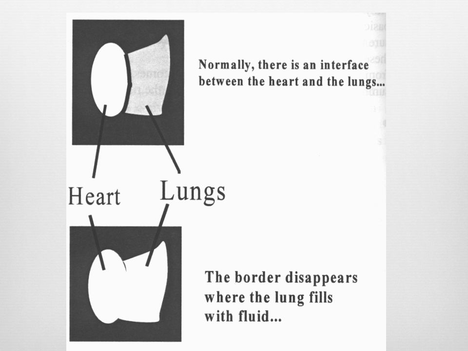
The radiographic density is the sum of all the densities and thickness interposed between the x-ray beam source and the film Adjacent densities are distinct and separated by a border or line The greater the difference in adjacent densities, the sharper the border Borders become indistinct and blend together into one common density when similar densities are in the same plane The radiographic projection must be properly oriented to the density border in order to show it Can see air/water border by looking at the side of the glass, but not if you look from the top or bottom of the glass

30
Film Penetration Over Penetrated Under penetrated
Over exposed, radiographs are too dark Too many RADs Under penetrated Under exposed, radiographs are too white Too few RADs

31
Newer techniques Radiographic image is digitalized and stored and viewed on a computer Image may be digitally enhanced and magnified Image may be printed for a hard copy Image may be transmitted by phone to a remote site

32
Common Radiographic Projections
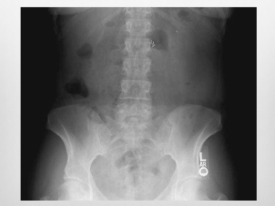
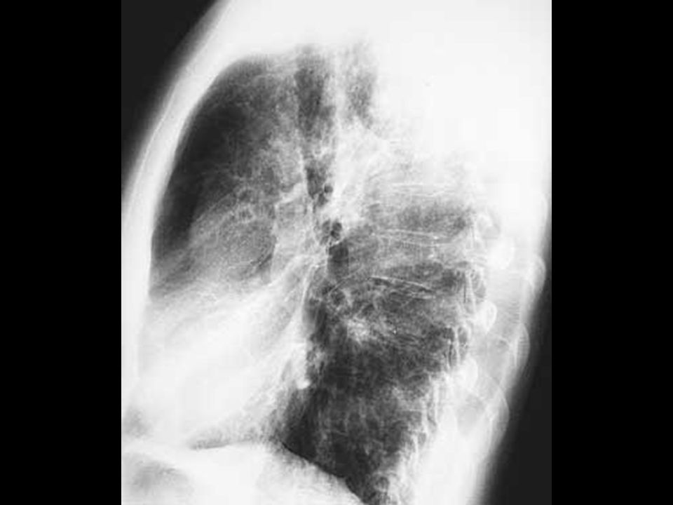
Anterior-posterior (AP) Posterior-anterior (PA) Lateral (right or left) Right lateral: right side against film Left lateral: left side against film Oblique (right & left) Special views (in handout)
 Posterior-anterior (PA) Lateral (right or left) Right lateral: right side against film. Left lateral: left side against film. Oblique (right & left) Special views (in handout)")
33
Taking X-Rays Place object of interest as close to the film as possible to avoid magnification Take multiple views from different angles Fractures require at least 2 views at 900 to each other When ordering x-rays, standard views are usually, taken unless otherwise specified

34
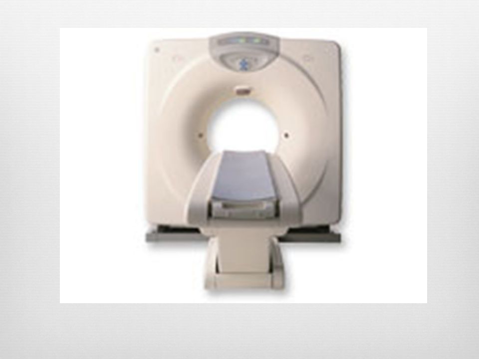
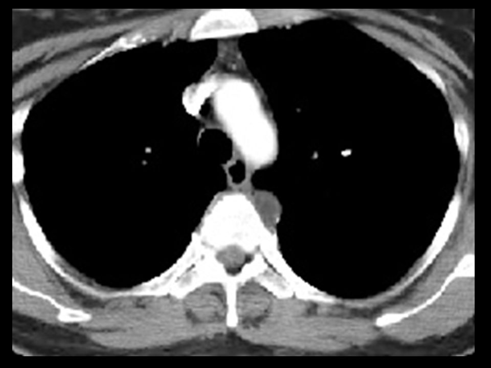
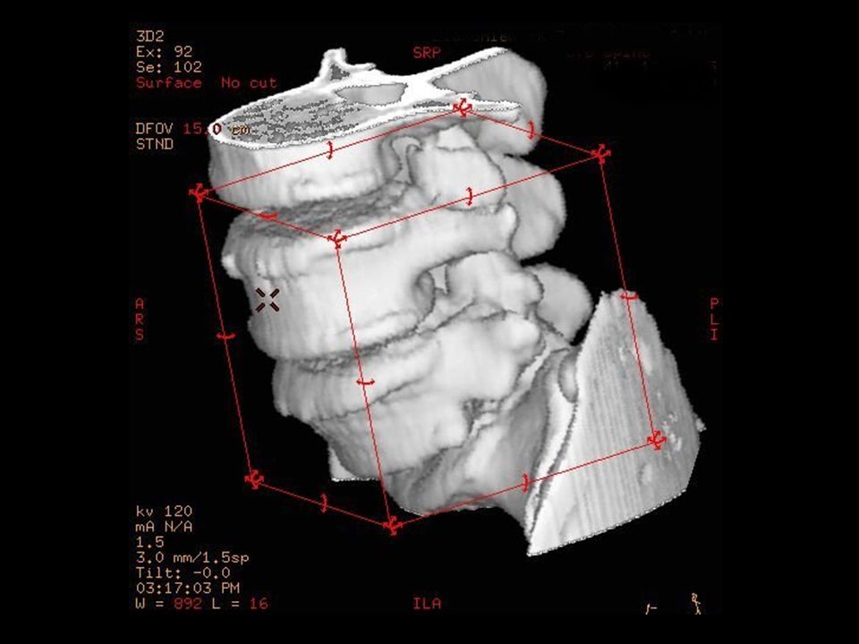
Computerized Tomography
Utilizes ionizing radiation Allows for rapid scanning in great detail Scans in the axial plane only Visualize bone better than soft tissue View the CT as if the pt was laying on back with feet toward you Many different densities Hounsfield Units (attenuation numbers) Air = -500; bone = +500 High speed helical and spiral CT 3-D CT Ultra-fast CT scan
 Air = -500; bone = High speed helical and spiral CT. 3-D CT. Ultra-fast CT scan.")
43
Fluoroscopy Technique that allows real-time visualization of the patient Continuous x-ray beam through the pt to cast an image on a fluorescing screen Uses Venous and angiographic procedures Fracture reduction

47
Diagnostic Ultrasound
Ultrasonic sound waves are generated and reflected back Frequency of the sound wave is > 15,000 cycles

48
Advantages Easy to use and noninvasive Inexpensive Portable
Can insert in every orifice

49
Disadvantage Bone and air-filled structures interfere with image
Indications Gall bladder disease Arterial and venous pathology Ob/gyn diagnostics Neonatal

54
Magnetic Resonance Imaging
Pt placed in the core of a large magnet Radio waves are passed through the body in a particular sequence of very short pulses Each pulse causes a responding pulse of radio waves to be emitted from the pt’s tissue Location from which the signals have originated is recorded by a detector and sent to a computer

56
Mobile MRI (semi truck)
")
57
Magnetic Resonance Imaging
Computer produces a 2D picture Hydrogen atoms in fat and water are imaged These atoms are aligned in a magnetic field Pulsed radiowaves knock these atoms out of alignment H+ atoms eventually reestablish the previous equilibrium with the surrounding magnet When this occurs, absorbed radiowaves are emitted Emitted waves are analyzed by a computer to produce the image

59
Axial View

60
Coronal View

61
Sagittal View

63
Magnetic Resonance Imaging
2 types of MRI phases T1 imaging (time to recovery) Fat appears white Air, cortical bone, CSF appear black T2 imaging (time to relaxation) Blood, CSF appear white
 Fat appears white. Air, cortical bone, CSF appear black. T2 imaging (time to relaxation) Blood, CSF appear white.")
64
T1 and T2 Images

65
T2 Image

66
T2 (top) and T1 (bottom) Axial
 and T1 (bottom) Axial")
67
Advantages Utilizes non-ionizing radiation
Can scan in multiple planes (axial, coronal, sagittal) Can scan in 1 mm to several cm increments Better soft tissue detail Noninvasive evaluation of cerebral blood vessels
 Can scan in 1 mm to several cm increments. Better soft tissue detail. Noninvasive evaluation of cerebral blood vessels.")
68
Disadvantages Poor bone detail Scanning time is much longer than CT
Can’t be scanned if you have certain kinds of metal implants Enclosed uncomfortable table Poor quality images of the abdomen and chest due to breathing and peristalsis causing greater motion artifact

69
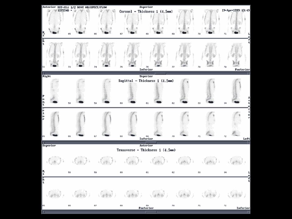
Radioisotope Scanning
Visualize living organs and tissues The isotope emits gamma rays for a brief period of time These rays are recorded by a gamma camera Can identify bone cancer, occult fractures, pulmonary emboli, thyroid cancer, cardiac ischemia

71
Technetium-99m The most useful tracer
Inexpensive Short half-life Readily available from portable generator High concentrations of isotope will congregate in tissues with increased metabolism Give less precise anatomic information

72
Technetium Technetium-99m-pertechnetate
Trapped by thyroid Technetium-99m-macroaggregated albumin Trapped by thyroid gland Tc-99m-methylene diphosphonate Trapped by bone tissue, used for bone scan

75
Thallium and Iodine Thallium-201 for evaluation of myocardial blood flow Iodine-131 for thyroid imaging

76
Cardiac Thallium Scan

79
Contrast Material Iodine contrast – Water soluble – Can be given IV, IA, intrathecal, endobronchial, or directly into the GI tract – Risk for allergic reaction – Can cause renal failure – Contraindicated in renal insufficiency

80
Contrast Material Barium contrast – Water insoluble – Given PO or rectally – Good for GI tract imaging – Very irritating if GI tract is perforated – Risk of fecal impaction, aspiration, perforation

81
Barium Enema

83
Hysterosalpingogram

84
Contrast Material Gastrograffin contrast – Water-soluble, iodine-based contrast – Good for GI tract imaging, but not as good as barium – Used if GI tract perforation is suspected – Promotes peristalsis – May cause serious lung edema in cases of esophageal-trachea fistulas

85
Contrast Material Gadolinium – Rare earth, metallic, paramagnetic contrast – Used only for MRI enhancement – No risk of an allergic reaction – Nontoxic to the kidneys

86
Radiologic Reports Radiology report content
Description of the findings Summary of findings May suggest clinical correlation or additional imaging studies to be performed Reports are sometimes noncommittal One should not make a diagnosis by imaging studies alone Final diagnosis and treatment requires: Clinical information (H&P, labs) Imaging studies Differential diagnosis
 Imaging studies. Differential diagnosis.")
87
Viewing Films Confirm the name and date of x-ray
Did you get what you wanted? Properly orient on the view box Orient film as if pt was facing you (chest) or away from you (spine) R and L indicators Up and down arrows Supine vs. standing indicators Evaluate the exposure
 or away from you (spine) R and L indicators. Up and down arrows. Supine vs. standing indicators. Evaluate the exposure.")
88
Conclusions and Questions

Similar presentations


 theory was developed 1972: The CT scan was invented by Godfrey.>")


 CT scanning or (CAT scanning) is using X-rays to create a 3D image of the inside of an object. CT stands for computed tomography.>")


>")


