Download presentation
Presentation is loading. Please wait.

1
NI RF and Communications Platform Hardware and Software
National Instruments Leadership Seminar April, 2002 NI RF and Communications Platform Hardware and Software Ron Harrison Product Marketing Manager RF & Communications The following session is designed to introduce you to communications design and test using LabVIEW and virtual instrumentation. Typically, communication systems are designed with digital signal processors (DSPs) and custom circuitry. What we will demonstrate is how through LabVIEW software, the basic building blocks of a communications system can be transferred from DSPs and custom circuits to reconfigurable, flexible software, which can target general purpose RF generators and analyzers. This greatly simplifies prototyping and test development. For the purpose of this demonstration, we will use the X10 wireless protocol which is a simple protocol for home automation and control. National Instruments CONFIDENTIAL
 and custom circuitry. What we will demonstrate is how through LabVIEW software, the basic building blocks of a communications system can be transferred from DSPs and custom circuits to reconfigurable, flexible software, which can target general purpose RF generators and analyzers. This greatly simplifies prototyping and test development. For the purpose of this demonstration, we will use the X10 wireless protocol which is a simple protocol for home automation and control. National Instruments CONFIDENTIAL.")
2
Increasing Bus Bandwidth Drives New Applications
National Instruments Leadership Seminar April, 2002 Increasing Bus Bandwidth Drives New Applications 24 Multichannel Audio High Resolution Digitizers PCI IF Communications PCI Express High Speed Imaging 20 16 Number of Bits Data acquisition 12 Instrument Control 8 {Objective: explain bus evolution and how hw technologies enable new applications for VI} The story of Virtual Instrumentation over last 20 years has been about leveraging the PC. The VI capability has grown with each generation of better and faster processors, hard disks, and memory. One PC technology in particular that has driven VI is the bus used to transfer data from the I/O system to the processor. To explain this chart briefly, we are plotting bus bandwidth in terms of sample rate versus #bits – for example, ISA can transfer data at 4 MB/s, so at 1 byte (8 bits) it can transfer 4 MS/s, and at 4 bytes it can transfer 1 MS/s. In days of ISA, the types of applications that could really be solved with a PC-based approach were primarily slow moving phenomena like sensor measurements, such as temperature and strain. Once the technology was there to solve these applications in a PC-based way, the industry moved to this approach and chart recorders all but disappeared. [BUILD] In the early 1990s, PCI, with 132 MB/s of bandwidth, opened a whole new world of measurements that could be solved with the PC. One example is audio measurements where off the shelf converters were also becoming widely available. Again, once the technology was available to solve these applications with a PC, custom boxes for audio measurements began to disappear. [BUILD] Today – the bus technology that’s emerging into mainstream is PCI Express, which provides a 45 fold increase in bandwidth over PCI. PCI Express brings communications applications, which often require 100s of megabytes of bus bandwidth, into the PC-based domain. TRANSITION: Fundamentally, what this is saying is that once you have the bus bandwidth to transfer the data to the PC, and the processor horsepower to perform the necessary analysis, you’ve turned the measurement into a software problem. ISA 1M 10M 100M 1G 10G 100G Sample Rate (Samples/s) National Instruments CONFIDENTIAL
 it can transfer 4 MS/s, and at 4 bytes it can transfer 1 MS/s. In days of ISA, the types of applications that could really be solved with a PC-based approach were primarily slow moving phenomena like sensor measurements, such as temperature and strain. Once the technology was there to solve these applications in a PC-based way, the industry moved to this approach and chart recorders all but disappeared. [BUILD] In the early 1990s, PCI, with 132 MB/s of bandwidth, opened a whole new world of measurements that could be solved with the PC. One example is audio measurements where off the shelf converters were also becoming widely available. Again, once the technology was available to solve these applications with a PC, custom boxes for audio measurements began to disappear. [BUILD] Today – the bus technology that’s emerging into mainstream is PCI Express, which provides a 45 fold increase in bandwidth over PCI. PCI Express brings communications applications, which often require 100s of megabytes of bus bandwidth, into the PC-based domain. TRANSITION: Fundamentally, what this is saying is that once you have the bus bandwidth to transfer the data to the PC, and the processor horsepower to perform the necessary analysis, you’ve turned the measurement into a software problem. ISA. 1M. 10M. 100M. 1G. 10G. 100G. Sample Rate (Samples/s) National Instruments CONFIDENTIAL.")
3
Evolving Wireless Standards
National Instruments Leadership Seminar April, 2002 Evolving Wireless Standards RFID GSM EDGE GPRS 1990 1995 2005 2000 2010 802.11 802.11a 802.11u 802.11j 802.11i 802.11k 802.11h 802.11g 802.11f 802.11e 802.11d 802.11b WiMAX – UWB TD-SCDMA UMTS cdma2000 HSDPA 802.22 WiMAX – e 802.20 AMPS IS95 IS136 IS54 ZigBee 802.11n {Objective: Demonstrate the overwhelming complexity in the wireless industry and why it needs a sw-based approach} There has been a proliferation of communications standards over the past years as wireless technology has become integrated into nearly ever industry and application. Think about how many cell phones have you had in the past few years? There’s a good chance that they all have used different standards from TDMA to GSM to 3G. Your phone today also may include other wireless protocols like Bluetooth and/or The challenge for design and test engineers is that the old approach for test was that you had a dedicated box for each standard. This worked OK when devices had a single protocol and the standard lasted for many years. Now – devices obviously have many more protocols and they are changing almost every year. [Transition] The old approach has broken down; what is required is a flexible software-based system that can evolve to test new standards… National Instruments CONFIDENTIAL

4
Virtual Instrumentation
National Instruments Leadership Seminar April, 2002 Virtual Instrumentation A Flexible, Reusable Approach to Test with Modular Hardware, Intuitive Software GSM Tester WLAN Tester Lower cost Higher performance Smaller size Flexible Easily upgraded User-defined Spectrum All in one PXI Platform! Radio Tester Multi-Protocol UUT Virtual instrumentation is a strategy that centers around modular hardware and intuitive software coupled together to create a user-defined instrument. For example, to completely test a smart phone, many different tests and consequently different pieces of test equipment must be employed to test functionality such as GSM, wireless LAN, spectrum shape, built-in radio functionality and other functions such as RFID. Using a PXI-based tester or hybrid PXI-GPIB-LAN system centered on the concept of virtual instrumentation offers a flexible, reusable approach to test. With modular hardware and intuitive software, much of this functionality can be implemented in software and you can achieve high-throughput validation and test that lowers cost and decreases footprint while maintaining ease-of-use and upgradeability. This is the key to address the various needs for automated testing across the industry – modular hardware, intuitive software. Power Meter RFID Tester National Instruments CONFIDENTIAL

5
PCI eXtensions for Instrumentation ( )
National Instruments Leadership Seminar April, 2002 PCI eXtensions for Instrumentation ( ) 132 MB/s PCI in an industrial form factor Standard Windows software Integrated timing and trigging Trigger bus with 8 lines Star Trigger with low-skew 10 MHz reference clock Open, multiple vendor standard PCI eXtensions for Instrumentation (PXI) is the open, multivendor standard for measurement and automation that delivers more than 10 times the performance of older measurement and automation architectures. With PXI, you automatically benefit from the low cost, ease of use, modularity, and flexibility of PC technology. Since it is based on PCI, it offers bandwidths of up to 132MB/s. Also, with the introduction of PCI Express in PXI, bandwidths are now reaching 6 GB/s! Another key benefit to the PXI platform is that it includes a timing and synchronization bus to easily coordinate measurement and automation between instruments. National Instruments CONFIDENTIAL
 132 MB/s PCI in an industrial form factor. Standard Windows software. Integrated timing and trigging. Trigger bus with 8 lines. Star Trigger with low-skew. 10 MHz reference clock. Open, multiple vendor standard. PCI eXtensions for Instrumentation (PXI) is the open, multivendor standard for measurement and automation that delivers more than 10 times the performance of older measurement and automation architectures. With PXI, you automatically benefit from the low cost, ease of use, modularity, and flexibility of PC technology. Since it is based on PCI, it offers bandwidths of up to 132MB/s. Also, with the introduction of PCI Express in PXI, bandwidths are now reaching 6 GB/s! Another key benefit to the PXI platform is that it includes a timing and synchronization bus to easily coordinate measurement and automation between instruments. National Instruments CONFIDENTIAL.")
6
Performance Benchmarks NI PXI-5660 2.7 GHz RF Signal Analyzer
National Instruments Leadership Seminar April, 2002 Performance Benchmarks NI PXI GHz RF Signal Analyzer Power in band: 30–200 times improvement Let’s look at a benchmark that illustrates the throughput advantages of the entire RF signal analyzer as compared to traditional instrumentation. This benchmark shows a comparison in making power-in-band measurements at several different frequency spans. Here, we see the powerful combination of the real-time bandwidth of the downconverter with the digitizer and the advantages of running the NI optimized FFT algorithms on the latest commercial processors. When making measurements like power-in-band, the RF signal analyzer delivers measurement throughput advantages of 30 to 200 times over traditional instrumentation. Advances in LabVIEW and PXI Instrumentation Seminar ni.com National Instruments CONFIDENTIAL

7
National Instruments Leadership Seminar
April, 2002 PXI vs. GPIB Reduce system size by 90% and increase wallet size by 100% with the NI modular instrumentation. Typical instrumentation systems contain oscilloscopes, sources, dmms, and switching systems. Combined, these components take up valuable space on in your lab or automated test system. With PXI users were able to reduce the system size by 90% AND cut the cost in half. A typical system with the GPIB instruments shown here would cost over $80,000. The same PXI modular instruments now cost about $40,000. That is a 100% increase in wallet size! NI Solution: $39,545 .67 ft3 (.019 m3) Traditional Solution: $82,972 6.12 ft3 (.1734 m3) National Instruments CONFIDENTIAL
 Traditional Solution: $82, ft3 (.1734 m3) National Instruments CONFIDENTIAL.")
8
National Instruments Leadership Seminar
April, 2002 PXI vs. GPIB Reduce system size by 97% and increase wallet size by 130% with the NI modular instrumentation. Typical instrumentation systems contain oscilloscopes, sources, dmms, and switching systems. Combined, these components take up valuable space on in your lab or automated test system. With PXI users were able to reduce the system size by 90% AND cut the cost in half. A typical system with the GPIB instruments shown here would cost over $80,000. The same PXI modular instruments now cost about $40,000. That is a 100% increase in wallet size! NI Solution: $2,999 .02 ft3 (562 cm3) Traditional Solution: $6,880 0.71 ft3 (20,037 cm3) National Instruments CONFIDENTIAL
 Traditional Solution: $6, ft3 (20,037 cm3) National Instruments CONFIDENTIAL.")
9
Advances in PC Bus Technology
National Instruments Leadership Seminar April, 2002 Advances in PC Bus Technology Do you remember this slide from the bus technology section earlier? We promised we would come back to it, so here we are to discuss the highlighted section—PCI Express. As you can see, it has incredibly low latency and very high bandwidth. In fact, only PCI has lower latency, and nobody has higher bandwidth. This is an incredibly combination for test and measurement applications. National Instruments CONFIDENTIAL

10
National Instruments Leadership Seminar
April, 2002 100 MHz Differential CLK PXI SYNC Control SYNC100 Star Trigger PXI Express 10 MHz CLK Controller System Timing Slot System Peripheral Peripheral Peripheral PXI Trigger Bus (8 TTL Triggers) Differential Star Triggers National Instruments CONFIDENTIAL
 Differential Star. Triggers. National Instruments CONFIDENTIAL.")
11
Compatibility of PXI and PXI Express Hybrid Slots
National Instruments Leadership Seminar April, 2002 Compatibility of PXI and PXI Express Hybrid Slots Trigger Bus Star Trigger System Ref Clock Reserved Pins 64/66 PCI Local Bus (typically unused) x8 PCIe (up to 2 GB/s) 32/33 PCI (132 MB/s Per system) This slide shows how a PXI Express Hybrid slot can be created that provides compatibility with existing PXI systems with PCI signaling, and will support future PXI Express modules with new PCI Express signaling. This hybrid slot is defined in the PXI Express Specification, however products do not exist and are not expected until the second half of 2006. PXI Express Hybrid PXI National Instruments CONFIDENTIAL
 x8. PCIe. (up to 2. GB/s) 32/33 PCI. (132 MB/s. Per system) This slide shows how a PXI Express Hybrid slot can be created that provides compatibility with existing PXI systems with PCI signaling, and will support future PXI Express modules with new PCI Express signaling. This hybrid slot is defined in the PXI Express Specification, however products do not exist and are not expected until the second half of PXI Express Hybrid. PXI. National Instruments CONFIDENTIAL.")
12
Flextronics Saves Millions with NI Test Platform
National Instruments Leadership Seminar April, 2002 Flextronics Saves Millions with NI Test Platform Challenge: Implementing standardized, scalable test stations to help test 500,000 products daily in 32 different countries. Products TestStand, PXI, Modular Instruments Application With Flextronics Test Standardization (FTS), the use of common hardware and software platforms guarantee that the software runs smoothly regardless of which operator, location or product tested. Using NI’s test platform, Flextronics has significantly reduced costs while keeping pace with technology advances in test. With fiscal year 2004 revenue of $14.5 billion, Flextronics is the leading electronics manufacturing services (EMS) provider focused on delivering services to technology companies in 32 countries on five continents. Flextronics manufactures and tests more than 500,000 products daily in industries ranging from communications infrastructure to consumer electronics. Standardized Test Platforms Save Millions With strong production test experience, Flextronics has identified several test methodologies key to improving product throughput in a variety of production situations. With the complexity of new products steadily increasing, Flextronics believes functional test is and will continue to be the largest growth test method in use within its factories. With a test strategy based on this belief, Flextronics is saving millions of dollars each year by developing and implementing standardized test platforms based on National Instruments test hardware and software in an initiative called Flextronics Test Standardization (FTS). In addition, using commercial off-the-shelf technology from National Instruments, Flextronics is able to integrate the latest software and hardware technologies as they are released without redesigning Flextronics test platforms. Test software, such as NI TestStand, and hardware, such as PXI and plug-in modular instrumentation, have been some of the most capable vehicles for maximizing efficiencies in functional test development and maintenance. FTS Improves Manufacturing Process The Flextronics common software platform provides a standard look and feel to all its test system designs. In addition, FTS software delivers a core architecture for test development and execution that is independent of the chosen hardware architecture and that offers a number of manufacturing advantages: Reduces development effort -- Using the modular framework provided by NI TestStand, engineers are able to develop and integrate reusable test modules into a more maintainable test system architecture. As a result, Flextronics software engineers can develop more sophisticated test systems in a fraction of the time. Requires less training -- FTS reduces costs by minimizing operator training through a common user interface. This provides greater flexibility in Flextronics factories because operators can work on a variety of test stations without specialized training. For software engineers, FTS standardizes test design guidelines so that engineers do not have to develop code each time from the ground up. Increases throughput -- The FTS NI TestStand Process Model is capable of testing multiple devices under test (DUTs) simultaneously, and it displays the test status for independent DUTs with real-time trend data. This is essential for increasing functional test coverage without increasing the time allotted in manufacturing for product functional test. Improves data collection -- FTS software outputs test results to local databases so that they are easily integrated into FlexFlow and other shop floor systems, which helps factories respond to test results and use the data history more effectively. Engineers share this same data with customers to help lead to better designs. In addition to the FTS software standardization initiative, the complete test architecture also includes hardware platforms that are CE and TÜV certified. Flextronics has designed standard, generic hardware platforms to cover the majority of their testing needs. The most functional platforms are PXI-based, and their interface connectivity is easily expandable, which results in high flexibility and reduced test development time. The platform configuration includes several PXI devices and GPIB instrumentation to cover most of the test applications. Because of its inherent modular approach, this platform offers complete hardware reuse, efficient asset management, and lower costs. FTS software tightly links the test system resources for maximum parallel process execution. NI Products Help Provide Quality Results The FTS common hardware platforms guarantee that the software runs smoothly. Also, by using commercial off-the-shelf technology such as NI TestStand, PXI, and modular instruments, Flextronics has significantly reduced costs while keeping pace with technology advances in test. Link to User Solution National Instruments CONFIDENTIAL
, the use of common hardware and software platforms guarantee that the software runs smoothly regardless of which operator, location or product tested. Using NI’s test platform, Flextronics has significantly reduced costs while keeping pace with technology advances in test. With fiscal year 2004 revenue of $14.5 billion, Flextronics is the leading electronics manufacturing services (EMS) provider focused on delivering services to technology companies in 32 countries on five continents. Flextronics manufactures and tests more than 500,000 products daily in industries ranging from communications infrastructure to consumer electronics. Standardized Test Platforms Save Millions With strong production test experience, Flextronics has identified several test methodologies key to improving product throughput in a variety of production situations. With the complexity of new products steadily increasing, Flextronics believes functional test is and will continue to be the largest growth test method in use within its factories. With a test strategy based on this belief, Flextronics is saving millions of dollars each year by developing and implementing standardized test platforms based on National Instruments test hardware and software in an initiative called Flextronics Test Standardization (FTS). In addition, using commercial off-the-shelf technology from National Instruments, Flextronics is able to integrate the latest software and hardware technologies as they are released without redesigning Flextronics test platforms. Test software, such as NI TestStand, and hardware, such as PXI and plug-in modular instrumentation, have been some of the most capable vehicles for maximizing efficiencies in functional test development and maintenance. FTS Improves Manufacturing Process The Flextronics common software platform provides a standard look and feel to all its test system designs. In addition, FTS software delivers a core architecture for test development and execution that is independent of the chosen hardware architecture and that offers a number of manufacturing advantages: Reduces development effort -- Using the modular framework provided by NI TestStand, engineers are able to develop and integrate reusable test modules into a more maintainable test system architecture. As a result, Flextronics software engineers can develop more sophisticated test systems in a fraction of the time. Requires less training -- FTS reduces costs by minimizing operator training through a common user interface. This provides greater flexibility in Flextronics factories because operators can work on a variety of test stations without specialized training. For software engineers, FTS standardizes test design guidelines so that engineers do not have to develop code each time from the ground up. Increases throughput -- The FTS NI TestStand Process Model is capable of testing multiple devices under test (DUTs) simultaneously, and it displays the test status for independent DUTs with real-time trend data. This is essential for increasing functional test coverage without increasing the time allotted in manufacturing for product functional test. Improves data collection -- FTS software outputs test results to local databases so that they are easily integrated into FlexFlow and other shop floor systems, which helps factories respond to test results and use the data history more effectively. Engineers share this same data with customers to help lead to better designs. In addition to the FTS software standardization initiative, the complete test architecture also includes hardware platforms that are CE and TÜV certified. Flextronics has designed standard, generic hardware platforms to cover the majority of their testing needs. The most functional platforms are PXI-based, and their interface connectivity is easily expandable, which results in high flexibility and reduced test development time. The platform configuration includes several PXI devices and GPIB instrumentation to cover most of the test applications. Because of its inherent modular approach, this platform offers complete hardware reuse, efficient asset management, and lower costs. FTS software tightly links the test system resources for maximum parallel process execution. NI Products Help Provide Quality Results The FTS common hardware platforms guarantee that the software runs smoothly. Also, by using commercial off-the-shelf technology such as NI TestStand, PXI, and modular instruments, Flextronics has significantly reduced costs while keeping pace with technology advances in test. Link to User Solution. National Instruments CONFIDENTIAL.")
13
Electronic Business 300 – The Rankings
PXI Industry Adoption Electronic Business 300 – The Rankings 16 of 20 top electronic business use PXI Source (Rankings): Electronic Business, August 2003 Source (PXI Use): National Instruments, June 2004
: Electronic Business, August Source (PXI Use): National Instruments, June")
14
Graphical Programming with NI LabVIEW
National Instruments Leadership Seminar April, 2002 Graphical Programming with NI LabVIEW LabVIEW is a highly productive graphical development environment with the performance and flexibility of a text-based programming language. With LabVIEW you use icons to represent functions, and you wire them together to determine the flow of data through your program, similar to creating flowcharts or block diagrams. In communication system block diagrams, the data or signal flows between processing blocks; LabVIEW’s dataflow-based nature follows intuitively the block diagram of a communication system. Each program in LabVIEW is called a virtual instrument, or VI. The VI serves as the primary building block of a LabVIEW application, and you can use it to modularize your code for efficient design, clear and concise documentation, and simplified maintenance. It has all the breadth and depth of a general-purpose programming language, but it is easy to use, increasing your productivity by decreasing the time required to develop your applications. Fast development with interactive configuration and graphical programming Tight integration of real-world I/O, measurement analysis, and data presentation Highly flexible engineering tool from desktop to RF manufacturing test National Instruments CONFIDENTIAL

15
Wireless Communication and Modulation
National Instruments Leadership Seminar April, 2002 Wireless Communication and Modulation A communication system comprises 3 components LabVIEW can be used to develop a communication system using the Modulation Toolkit Bit Generation Source Coding Channel Coding Modulation Modulation Bits Bits Bits IQ Galois PN Fibonacci PN Data compression Digital filters Custom VIs M-Script Custom dlls Hamming, Golay, Reed-Solomon, Bose-Chaudhari-Hocquenghem (BCH), Convolutional, Spreading Interleavers, Puncturing Equalization AM, FM, PM ASK, FSK, MSK, GMSK, PAM, PSK, QAM,… OFDM BER, burst timing, frequency deviation, MER, EVM, ρ(rho) You may have heard about an approach called a software-defined Radio (SDR). In a generic digital SDR, the communication system can be broken down into 3 components (which are typically performed with DSP hardware): First, you generate a digital signal containing the message you want to transfer, for example an audio file. Next, is Source Coding, which takes the bits and usually compresses them to transfer less information. An example is the ubiquitous MPEG-3, or MP3, coding format. In Channel Coding, redundant information is added to the signal to optimize its transition over a channel, like a cable or a wireless link. Finally, you Modulate the signal, by turning the digital bits, or symbols, into an analog signal that is transmitted onto a carrier. The concept of a software defined radio is that with these generic software blocks, you can configure them to create any type of radio or communication system using generic transceiver hardware. [BUILD] LabVIEW has a native, comprehensive set of algorithms and tools to build a software-defined radio system. With these blocks in LabVIEW, you can create any communications system just by wiring together different LabVIEW VIs – or functions. National Instruments CONFIDENTIAL
, Convolutional, Spreading. Interleavers, Puncturing. Equalization. AM, FM, PM. ASK, FSK, MSK, GMSK, PAM, PSK, QAM,… OFDM. BER, burst timing, frequency deviation, MER, EVM, ρ(rho) You may have heard about an approach called a software-defined Radio (SDR). In a generic digital SDR, the communication system can be broken down into 3 components (which are typically performed with DSP hardware): First, you generate a digital signal containing the message you want to transfer, for example an audio file. Next, is Source Coding, which takes the bits and usually compresses them to transfer less information. An example is the ubiquitous MPEG-3, or MP3, coding format. In Channel Coding, redundant information is added to the signal to optimize its transition over a channel, like a cable or a wireless link. Finally, you Modulate the signal, by turning the digital bits, or symbols, into an analog signal that is transmitted onto a carrier. The concept of a software defined radio is that with these generic software blocks, you can configure them to create any type of radio or communication system using generic transceiver hardware. [BUILD] LabVIEW has a native, comprehensive set of algorithms and tools to build a software-defined radio system. With these blocks in LabVIEW, you can create any communications system just by wiring together different LabVIEW VIs – or functions. National Instruments CONFIDENTIAL.")
16
Wireless Communication and Modulation
National Instruments Leadership Seminar April, 2002 Wireless Communication and Modulation Software-Defined Radio (SDR) = Software-defined communications on reconfigurable HW LabVIEW can be used to develop any SDR Source Coding Channel Coding Modulation Bits IQ Bit Generation Source Coding Channel Coding Modulation Bits IQ Bit Generation To illustrate the concept of a software-defined radio, we have pulled the protocol and signal development into software in which we are implementing it using LabVIEW and the Modulation Toolkit. We then target general purpose RF hardware such as the RF vector signal generator to correctly generate our communication signal. National Instruments CONFIDENTIAL
 = Software-defined communications on reconfigurable HW. LabVIEW can be used to develop any SDR. Source Coding. Channel Coding. Modulation. Bits. IQ. Bit. Generation. Source Coding. Channel Coding. Modulation. Bits. IQ. Bit. Generation. To illustrate the concept of a software-defined radio, we have pulled the protocol and signal development into software in which we are implementing it using LabVIEW and the Modulation Toolkit. We then target general purpose RF hardware such as the RF vector signal generator to correctly generate our communication signal. National Instruments CONFIDENTIAL.")
17
DAB Emission Block Diagram
National Instruments Leadership Seminar April, 2002 DAB Emission Block Diagram Source Coding Channel Coding {Objective: show new specification and demonstrate the 3 basic steps} A specific example of this is DAB, Digital Audio Broadcast – a technology pervasive in Europe and Asia. DAB is similar to FM radio, but it’s all digital, so you’re able to broadcast more information at a higher quality. What we’re looking at on this slide is the actual diagram is the DAB emission block diagram as found in the digital audio broadcast specification. I don’t expect you take away all the details of this diagram, but I will briefly point out the basic flow. [BUILD] First there is source coding, you can probably see the MPEG-II block, for example. Then, the signal is coded for optimal reception over a noisy wireless broadcast channel. Finally, it is modulated onto multiple orthogonal carriers using OFDM (Orthogonal Frequency Division Multiplexing). OFDM is a very popular modulation format in many emerging wireless standard and the new modulation toolkit has OFDM capabilities. [TRANSITION] Even this complex block diagram can be easily represented with in the software of a software-defined radio. In fact, the LabVIEW representation of this system looks very similar to the block diagram of this specification. Modulation *Final Draft ETSI EN v1.4.1 ( ) National Instruments CONFIDENTIAL
. OFDM is a very popular modulation format in many emerging wireless standard and the new modulation toolkit has OFDM capabilities. [TRANSITION] Even this complex block diagram can be easily represented with in the software of a software-defined radio. In fact, the LabVIEW representation of this system looks very similar to the block diagram of this specification. Modulation. *Final Draft ETSI EN v1.4.1 ( ) National Instruments CONFIDENTIAL.")
18
LabVIEW DAB Emission Block Diagram
National Instruments Leadership Seminar April, 2002 LabVIEW DAB Emission Block Diagram Source Coding Channel Coding {Objective: demonstrate how LabVIEW intuitively represents complex standards such as the one we just looked at} This diagram is the LabVIEW block diagram (code) for that same DAB transmitter. Notice that it follows nicely from the standard communications block diagrams. LabVIEW’s intuitive data-flow oriented model allows engineers to easily develop system-level models, simulations and hardware enabled tests to test and verify transceiver operation. Here you can see a 1-1 correlation – through the MPEG source coding, the channel coding steps, and modulated using OFDM. The advantage of this approach is that if DAB, or whichever communication standard you are representing changes, and as we saw it inevitably will – you can just go into the diagram and tweak it – each of these blocks are editable and customizable for parameter and configuration changes; with this approach you no longer have to rely on the instrumentation hardware vendor to come out with a new instrument. [Transition] So now we have a complex broadcast scheme which we can transfer directly out of vector generator to prototype a new design or to test a DAB-compliant receiver. Modulation National Instruments CONFIDENTIAL
 for that same DAB transmitter. Notice that it follows nicely from the standard communications block diagrams. LabVIEW’s intuitive data-flow oriented model allows engineers to easily develop system-level models, simulations and hardware enabled tests to test and verify transceiver operation. Here you can see a 1-1 correlation – through the MPEG source coding, the channel coding steps, and modulated using OFDM. The advantage of this approach is that if DAB, or whichever communication standard you are representing changes, and as we saw it inevitably will – you can just go into the diagram and tweak it – each of these blocks are editable and customizable for parameter and configuration changes; with this approach you no longer have to rely on the instrumentation hardware vendor to come out with a new instrument. [Transition] So now we have a complex broadcast scheme which we can transfer directly out of vector generator to prototype a new design or to test a DAB-compliant receiver. Modulation. National Instruments CONFIDENTIAL.")
19
Software-Defined Communication Applications
National Instruments Leadership Seminar Software-Defined Communication Applications April, 2002 MIMO Alphautomazione /Lyocom Alphautomazione /Lyocom SeaSolve VI Service Network MindReady MindReady SeaSolve Tire Pressure Monitoring AmFax Wineman Technologies AmFax DAQTron SeaSolve AmFax This software-defined approach to RF and communications design and test applies to many of todays most recognizable standards. This includes ZigBee, WiMAX, XM and Sirius Satellite Radio, MIMO applications, Wireless LAN, GSM, Bluetooth, RFID and more. National Instruments works very closely with several product partners to deliver these industry software solutions built on National Instruments LabVIEW software and the PXI hardware platform. With a software-defined approach, this means you can integrate tests for any or all communications standards on a single LabVIEW/PXI platform. Some of the specific Alliance Members we work with on these solutions includes: SeaSolve (Domain) – ZigBee, b&g, WiMAX AmFax – (Integrator) - Cellular Test, Bluetooth MindReady (Integrator) – Radio Test VI Service Networks (Domain) – RFID, Cellular Wineman (Integrator) – RF Tire Pressure Summitek (Domain Partner) – Spectrum Monitoring Ascor (Product Partner) – Up/Down Converters DAQTron (Integrator) – Digital Video Broadcast Phase Matrix (Product Partner) – Up/Down Converters Alphautomazione/Lyocom – WiMax, n MIMO NI LabVIEW Communication Software NI PXI RF Hardware National Instruments CONFIDENTIAL
 – ZigBee, b&g, WiMAX. AmFax – (Integrator) - Cellular Test, Bluetooth. MindReady (Integrator) – Radio Test. VI Service Networks (Domain) – RFID, Cellular. Wineman (Integrator) – RF Tire Pressure. Summitek (Domain Partner) – Spectrum Monitoring. Ascor (Product Partner) – Up/Down Converters. DAQTron (Integrator) – Digital Video Broadcast. Phase Matrix (Product Partner) – Up/Down Converters. Alphautomazione/Lyocom – WiMax, n MIMO. NI LabVIEW Communication Software. NI PXI RF Hardware. National Instruments CONFIDENTIAL.")
20
NI Instrumentation Platform for RF & Communications
National Instruments Leadership Seminar April, 2002 NI Instrumentation Platform for RF & Communications RF and Microwave Hardware RF Vector Signal Analyzer 2.7 GHz, 20 MHz RTB RF Vector Signal Generators 2.7 GHz, 20 MHz RTB Analog RF Signal Generators 6.6 GHz CW w/ analog modulation RF Preamplifier 3 GHz, 30 dB programmable gain RF & Microwave Switches Up to 26.5 GHz, MUX, GP Relays IF / Baseband Hardware High-Speed Digitizers Up to 24 bit, Up to 1 GS/s Signal Generators Up to 16 bit, Up to 300 MS/s High-Speed Digital I/O Up to 32 ch, 400 Mbps RF & Communications Software NI Modulation Toolkit Communications signal generation, analysis and test NI Spectral Measurements Toolkit Power in-band, ACPR, spectral analysis,... The previous demo of a Communications System only used LabVIEW and the Modulation Toolkit. This was all done in software in a simulation only mode. At the end of the presentation, we will do the same demo, but this time, we will include hardware (hardware-in-the-loop). We will use the PXI RF platform from National Instruments which will include the following instruments: 1. NI PXI GHz RF Vector Signal Analyzer 9 kHz to 2.7 GHz 20 MHz real-time bandwidth -130 to +30 dBm signal level range 14-bit resolution, 64 MS/s digitizer High-stability OCXO timebase 32 or 64 MB memory 2. NI PXI GHz RF Vector Signal Generator 250 kHz to 2.7 GHz -145 to +10 dBm output power 355 nHz resolution Quadrature digital upconversion (In one customers application, signal generation times went from over one minute to 4 seconds with the 5671). 32, 256, or 512 MB of onboard memory 3. NI Modulation Toolkit Quality measurements including EVM, modulation error ratio (MER), and ρ (rho) Powerful 3D eye diagrams enhance the suite of traditional 2D eye, trellis, and constellation plots Handles standard and custom modulation formats(AM, FM, PM, ASK, FSK, MSK, GMSK, PSK, QPSK, PAM, QAM) Simulate and measure impairments including DC offset, IQ gain imbalance, and quadrature skew Measurements including bit-error rate (BER), phase error, burst timing, and frequency deviation More than 100 source code example programs In addition to the products mentioned above, the NI PXI RF platform also consists these products: The new PXI-5690 RF Preamplifier that pushes the noise floor of the 5660 to below -165 dBm. RF switches up to 26.5 GHz The Spectral Measurements Toolkit for LabVIEW and LabWindows/CVI National Instruments CONFIDENTIAL
. We will use the PXI RF platform from National Instruments which will include the following instruments: 1. NI PXI GHz RF Vector Signal Analyzer. 9 kHz to 2.7 GHz. 20 MHz real-time bandwidth to +30 dBm signal level range. 14-bit resolution, 64 MS/s digitizer. High-stability OCXO timebase. 32 or 64 MB memory. 2. NI PXI GHz RF Vector Signal Generator. 250 kHz to 2.7 GHz to +10 dBm output power. 355 nHz resolution. Quadrature digital upconversion (In one customers application, signal generation times went from over one minute to 4 seconds with the 5671). 32, 256, or 512 MB of onboard memory. 3. NI Modulation Toolkit. Quality measurements including EVM, modulation error ratio (MER), and ρ (rho) Powerful 3D eye diagrams enhance the suite of traditional 2D eye, trellis, and constellation plots. Handles standard and custom modulation formats(AM, FM, PM, ASK, FSK, MSK, GMSK, PSK, QPSK, PAM, QAM) Simulate and measure impairments including DC offset, IQ gain imbalance, and quadrature skew. Measurements including bit-error rate (BER), phase error, burst timing, and frequency deviation. More than 100 source code example programs. In addition to the products mentioned above, the NI PXI RF platform also consists these products: The new PXI-5690 RF Preamplifier that pushes the noise floor of the 5660 to below -165 dBm. RF switches up to 26.5 GHz. The Spectral Measurements Toolkit for LabVIEW and LabWindows/CVI. National Instruments CONFIDENTIAL.")
21
National Instruments Leadership Seminar
April, 2002 RF Vector Signal Generation NI PXI GHz Vector Signal Generator with Digital Upconversion Measurement Performance 250 kHz to 2.7 GHz 20 MHz Real-Time Bandwidth -145 to +10 dBm power level 50 ppb frequency accuracy Flexible Modulation Software ASK, FSK, MSK, GMSK, PSK, QPSK, /4 DQPSK, QAM, AM, FM, PM, OFDM, Custom Deep Onboard Memory 32, 256, and 512 MB memory options I just wanted to highlight some of the RF modules that exist in PXI. In addition to National Instruments RF vector signal generator, Aeroflex also has an RF signal generator in PXI. And just a few weeks ago, Agilent launched a 500 MHz Arbitrary Waveform Generator in CompactPCI which is PXI compatiable. A big advantage with the RF vector signal generator here is its ability to generate all the standard modulation formats as simple as the analog modulation formats and ASK to the more complex 256 QAM, even custom formats can be developed and generated. This flexibility to generate all these different formats is inherent to the virtual instrumentation concept. If we abstract the hardware, then the flexibility to generate all the modulation formats, even custom formats, lies in the software. National Instruments CONFIDENTIAL

22
National Instruments Leadership Seminar
April, 2002 RF & Microwave Signal Generators NI PXI-565x 500kHz to 6.6GHz Signal Generators w/ DDS & Modulation High-resolution frequency sweeping, hopping, and phase-continuous frequency sweeping -110 dBc/Hz phase noise at 1 GHz, 10 kHz offset FM, 2-FSK, OOK modulation Modulating waveforms include sine, triangle, square, 31-order PRBS, user-defined 1020-bit Applications Use as tunable local oscillator or clock source Use with NI PXI-5660 RF vector signal analyzer for stimulus response or tracking generator applications Release End of Q106 PXI-565X Series Data Sheet Frequency Range PXI kHz to 1.5 GHz* PXI kHz to 3.3 GHz* PXI kHz to 6.6 GHz* *Tunable down to 100 kHz with amplitude uncalibrated. Resolution Step Error 1 MHz to 1.5 GHz 1 Hz Hz max 1.5 GHz to 3.0 GHz 1 Hz Hz max 3.0 GHz to 6.6 GHz 2 Hz 1.5 Hz max Accuracy Same as timebase Switching Speed 0.1 ppm of final frequency < 5 ms 0.01 ppm of final frequency <20 ms Sweep Modes Operating modes frequency step, continuous phase*, frequency list Frequency list points ? Dwell time 5 ms minimum ? *over limited freq. range ~ few MHz Reference Clock Internal Clock Stability Aging +/- 5 ppm max. /year Temperature (0 oC to 50 oC) +/- 1 ppm max. Internal Reference Output Frequency MHz Amplitude 1 V p-p typical into 50 W Coupling AC Output Impedance 50 W External Reference Input Amplitude V p-p to 1.5 V p-p into 50 W Input impedance 50 W Spectral Purity SSB Phase 10 kHz offset At 100 MHz < -125 dBc/Hz typ. At 500 MHz < -112 dBc/Hz typ. At 1 GHz < -105 dBc/Hz typ. At 2 GHz < -98 dBc/Hz typ. At 3 GHz < -95 dBc/Hz typ. At 4 GHz < -93 dBc/Hz typ. At 5 GHz < -90 dBc/Hz typ. At 6 GHz < -90 dBc/Hz typ. Residual FM At 500 MHz < 1.6Hz rms At 1GHz < 2.0 Hz rms Harmonics (<= 0 dBm) 1 MHz to 1 GHz < -15 dBc 1 GHz to 3.3 GHz < -25 dBc 3.3 GHz to 6 GHz < -20 dBc Nonharmonics (< +3 dBm) > 1 kHz offset > 100 kHz offset 1 MHz to 50 MHz < -65 dBc < -75 dBc 50 MHz to 3.3 GHz < -65 dBc < -70 dBc 3.3 GHz to 6 GHz < -50 dBc < Subharmonic Products 1MHz to 3.3 GHz None 3.3 GHz to 4 GHz < -25 dBc ? 4 GHz to 6 GHz < -25 dBc ? Figure 1 SSB phase noise characteristic at 1 GHz carrier Amplitude 1 MHz to 10 MHz dBm to 5 dBm 10 MHz to 500 MHz dBm to 10 dBm 500 MHz to 1.6 GHz -90 dBm to 10 dBm 1.6 GHz to 2.9 GHz -80 dBm to 10 dBm 2.9 GHz to 3.3 GHz -70 dBm to 7 dBm 3.3 GHz to 3.7 GHz -60 dBm to 7 dBm 3.7 GHz to 5.0 GHz dBm to 4 dBm 5.0 GHz to 6.6 GHz dBm to 0 dBm Maximum available power 2 to 3 dB above maximum specified range Resolution dB Level accuracy Less than 3.3 GHz > -40 dBm +/ dB < -40 dBm +/- 1.8 dB Greater than 3.3GHz > -40 dBm +/- 1.0 dB < -40 dBm +/- 2.0 dB Amplitude settling time 0.1 dB of final value < 20 ms 0.01 dB of final value < 500 ms Reverse power protection RF Watts DC V Trip Point 1 Watt typical SWR 1 MHz to 3 GHz < 1.8:1 typ. 3 GHz to 6 GHz < 2.0:1 typ. Output impedance 50 W Modulation Frequency Modulation Mode FSK, 4-FSK Maximum Rate kHz * TBD Maximum deviation 2 MHz ** TBD Distortion TBD Phase Modulation Mode PSK, 4-PSK Maximum Rate kHz * Maximum deviation 5 radians** TBD Amplitude Modulation Mode level OOK* Maximum Rate kHz * Internal modulation source Waveforms Sine, Triangle, Square, 9-bit PRBS, 1000 bit pattern Rate Hz to 100 kHz ** TBD Fixed Frequency Source Frequency range Few Hundred MHz Amplitude 4 dBm into 50 W load Phase noise 10 KHz offset typical Enable/disable Yes Frequency accuracy Same as timebase National Instruments CONFIDENTIAL
 +/- 1 ppm max. Internal Reference Output. Frequency 10 MHz. Amplitude 1 V p-p typical into 50 W. Coupling AC. Output Impedance 50 W. External Reference Input. Amplitude 0.2 V p-p to 1.5 V p-p into 50 W. Input impedance 50 W. Spectral Purity. SSB Phase 10 kHz offset. At 100 MHz < -125 dBc/Hz typ. At 500 MHz < -112 dBc/Hz typ. At 1 GHz < -105 dBc/Hz typ. At 2 GHz < -98 dBc/Hz typ. At 3 GHz < -95 dBc/Hz typ. At 4 GHz < -93 dBc/Hz typ. At 5 GHz < -90 dBc/Hz typ. At 6 GHz < -90 dBc/Hz typ. Residual FM. At 500 MHz < 1.6Hz rms. At 1GHz < 2.0 Hz rms. Harmonics (<= 0 dBm) 1 MHz to 1 GHz < -15 dBc. 1 GHz to 3.3 GHz < -25 dBc. 3.3 GHz to 6 GHz < -20 dBc. Nonharmonics (< +3 dBm) > 1 kHz offset > 100 kHz offset. 1 MHz to 50 MHz < -65 dBc < -75 dBc. 50 MHz to 3.3 GHz < -65 dBc < -70 dBc. 3.3 GHz to 6 GHz < -50 dBc < Subharmonic Products. 1MHz to 3.3 GHz None. 3.3 GHz to 4 GHz < -25 dBc 4 GHz to 6 GHz < -25 dBc Figure 1 SSB phase noise characteristic at 1 GHz carrier. Amplitude. 1 MHz to 10 MHz -100 dBm to 5 dBm. 10 MHz to 500 MHz -100 dBm to 10 dBm. 500 MHz to 1.6 GHz -90 dBm to 10 dBm. 1.6 GHz to 2.9 GHz -80 dBm to 10 dBm. 2.9 GHz to 3.3 GHz -70 dBm to 7 dBm. 3.3 GHz to 3.7 GHz -60 dBm to 7 dBm. 3.7 GHz to 5.0 GHz -50 dBm to 4 dBm. 5.0 GHz to 6.6 GHz -50 dBm to 0 dBm. Maximum available power 2 to 3 dB above maximum specified range. Resolution 0.1 dB. Level accuracy. Less than 3.3 GHz. > -40 dBm +/ dB. < -40 dBm +/- 1.8 dB. Greater than 3.3GHz. > -40 dBm +/- 1.0 dB. < -40 dBm +/- 2.0 dB. Amplitude settling time. 0.1 dB of final value < 20 ms dB of final value < 500 ms. Reverse power protection. RF 2 Watts. DC 25 V. Trip Point 1 Watt typical. SWR. 1 MHz to 3 GHz < 1.8:1 typ. 3 GHz to 6 GHz < 2.0:1 typ. Output impedance 50 W. Modulation. Frequency Modulation. Mode 2-FSK, 4-FSK. Maximum Rate 100 kHz * TBD. Maximum deviation 2 MHz ** TBD. Distortion TBD. Phase Modulation. Mode 2-PSK, 4-PSK. Maximum Rate 100 kHz * Maximum deviation 5 radians** TBD. Amplitude Modulation. Mode 2-level OOK* Maximum Rate 200 kHz * Internal modulation source. Waveforms Sine, Triangle, Square, 9-bit PRBS, 1000 bit pattern. Rate 10 Hz to 100 kHz ** TBD. Fixed Frequency Source. Frequency range Few Hundred MHz. Amplitude 4 dBm into 50 W load. Phase noise 10 KHz offset typical. Enable/disable Yes. Frequency accuracy Same as timebase. National Instruments CONFIDENTIAL.")
23
RF Vector Signal Analyzer NI PXI-5661 2.7 GHz VSA w/ DDC
National Instruments Leadership Seminar April, 2002 RF Vector Signal Analyzer NI PXI GHz VSA w/ DDC Measurement Performance 9 kHz to 2.7 GHz 20 MHz real-time bandwidth Up to 80 dB SFDR 50 ppb frequency accuracy 14-bit resolution, 100 MS/s digitizer 64 or 256 MB memory 30% of size, weight of competing instruments Wide Range of Analysis Modulation and Spectral Measurement Toolkits Measurement Throughput 30-200x faster RF measurements > 100 MB/s transfer rates for real-time measurements The same is true on the acquisition side. Here is National Instruments RF vector signal analyzer. Aeroflex also has an RF signal analyzer. Again, if we abstract the hardware, the software becomes the tool. This gives the user the flexibility to access customizable functionality and adapt to the changing design, test, and manufacturing requirements in addition to the new standards hitting the market. National Instruments CONFIDENTIAL

24
RF/Microwave Switches
National Instruments Leadership Seminar April, 2002 RF/Microwave Switches Multiplexer PXI x1 500 MHz PXI x1 1.3 GHz PXI x1 4 GHz PXI-2596 Dual 6x GHz PXI x1 Terminated 26.5 GHz General-Purpose Relays PXI-2598 Dual Transfer Switch 26.5 GHz PXI-2599 Dual SPDT 26.5 GHz Matrix PXI terminal sparse matrix 500 MHz Slides in red to be released at NIWeek 05. National Instruments CONFIDENTIAL

25
26.5 GHz PXI Switch Modules Four different modules
PXI-2596: Dual 6x1 mux PXI-2597: 6x1 terminated mux PXI-2598: Dual transfer switch PXI-2599: Dual SPDT relay Specifications at 26.5 GHz <0.7 dB insertion loss >50 dB isolation Even better at lower frequencies Using Radiall relays (off the shelf)
")
26
National Instruments Leadership Seminar
April, 2002 Modulation Toolkit 3.1 Analog and Digital modulation formats AM, FM, PM ASK, FSK, MSK, GMSK, PAM, PSK, QAM Custom Visualization 2D and 3D Eye, Trellis, Constellation Modulation Analysis BER, MER, EVM, burst timing, frequency deviation, ρ (rho) Impairments Additive White Gaussian Noise (AWGN) DC offset, Quadrature skew, IQ gain imbalance, phase noise Equalization, Channel Coding, Channel Models Sometimes too much flexibility can imply more development time. For example, if I wanted to develop and test an RFID device or a wireless sensor and I needed to modulated and demodulate ASK and FSK, I would not want to start writing code to modulate and demodulate these formats. Or if I was using an RF signal analyzer to do spectral monitoring and I needed to demodulate many different modulation formats, it could be a daunting task writing code for this application. To help in this area, National Instruments ships the Modulation Toolkit with every vector signal generator that allows all the standard modulation formats to be generated, even custom formats. This way, the code is already written for the standard formats – then you can build on top of these basic building blocks. The standard eye, trellis and constellation diagrams are already written as well as analysis functions that can be used with any PXI signal analyzer. Functions are written for MER and EVM as an example. On the signal generation side, you also have the ability to inject impairments into the system such as Gaussian Noise, IQ gain imbalance, and phase noise, and these impairments then can be measured at the output of the device with a signal analyzer using the Modulation Toolkit. So, while there is a tremendous amount of flexibility, the building blocks exist so you can start building your system quickly. National Instruments CONFIDENTIAL
 Impairments. Additive White Gaussian Noise (AWGN) DC offset, Quadrature skew, IQ gain imbalance, phase noise. Equalization, Channel Coding, Channel Models. Sometimes too much flexibility can imply more development time. For example, if I wanted to develop and test an RFID device or a wireless sensor and I needed to modulated and demodulate ASK and FSK, I would not want to start writing code to modulate and demodulate these formats. Or if I was using an RF signal analyzer to do spectral monitoring and I needed to demodulate many different modulation formats, it could be a daunting task writing code for this application. To help in this area, National Instruments ships the Modulation Toolkit with every vector signal generator that allows all the standard modulation formats to be generated, even custom formats. This way, the code is already written for the standard formats – then you can build on top of these basic building blocks. The standard eye, trellis and constellation diagrams are already written as well as analysis functions that can be used with any PXI signal analyzer. Functions are written for MER and EVM as an example. On the signal generation side, you also have the ability to inject impairments into the system such as Gaussian Noise, IQ gain imbalance, and phase noise, and these impairments then can be measured at the output of the device with a signal analyzer using the Modulation Toolkit. So, while there is a tremendous amount of flexibility, the building blocks exist so you can start building your system quickly. National Instruments CONFIDENTIAL.")
27
Generation with NI RF Vector Signal Generators
National Instruments Leadership Seminar April, 2002 Generation with NI RF Vector Signal Generators Protocol Modulated Waveform The following is the process behind getting from a protocol to final RF signal generation. Initially, we created the X10 baseband waveform according to the specifications outlined on the previous slides. Once that is done, since X10 uses ASK modulation or more precisely on-off keying (OOK) we then modulate our baseband signal onto a 310 MHz carrier. We see from the middle image that the high-frequency carrier is on when we have high-time in our X10 protocol and off when we have low-time. Finally, this modulated waveform is downloaded to the RF vector signal generator and played out the RF port. Note: This explanation is simplifying the generation process slightly as our waveform is not quite RF when we download it. What actually occurs is that we modulate our signal onto an intermediate frequency within the range of an arbitrary waveform generator (usually MHz) and then we upconvert that block of frequencies to be centered at our carrier frequency of 310 MHz. Generate IF Upconvert To RF Download to AWG National Instruments CONFIDENTIAL
 we then modulate our baseband signal onto a 310 MHz carrier. We see from the middle image that the high-frequency carrier is on when we have high-time in our X10 protocol and off when we have low-time. Finally, this modulated waveform is downloaded to the RF vector signal generator and played out the RF port. Note: This explanation is simplifying the generation process slightly as our waveform is not quite RF when we download it. What actually occurs is that we modulate our signal onto an intermediate frequency within the range of an arbitrary waveform generator (usually MHz) and then we upconvert that block of frequencies to be centered at our carrier frequency of 310 MHz. Generate IF. Upconvert To RF. Download to AWG. National Instruments CONFIDENTIAL.")
28
National Instruments Leadership Seminar
April, 2002 RF Academic Bundle From Theory To Technology RF & Communications Academic Bundle RF Measurement Fundamentals In-Class Demos Lab Templates Technology Specific Projects Benefits of Theory to Technology: Solidifies the Learning Process We decided to take students from theory to technology with a 4-step process, Which coincidentally maps directly to the graphical system design message Theory Design Prototype Deploy National Instruments CONFIDENTIAL

29
National Instruments Leadership Seminar
April, 2002 RF Fundamentals What are they? Topical descriptions of concepts No NI spin – only meant to teach the concept DevZone documents Why do them? Establish NI as expert in the RF field Googlization for many RF buzzwords Build on existing framework of Measurement Fundamentals National Instruments CONFIDENTIAL

30
Example: Orthogonal Frequency Division Multiplexing
National Instruments Leadership Seminar April, 2002 RF Fundamentals Example: Orthogonal Frequency Division Multiplexing National Instruments CONFIDENTIAL

31
National Instruments Leadership Seminar
April, 2002 In-Class Demos Maximizing Spectral Efficiency Multi-Channel Implementations Analog Modulation Physical Channel Limitations Digital Modulation Frequency Modulation Amplitude FSK QAM ASK PSK Carrier Recovery Noise vs. M-ary Channel Coding Spectral Leakage Bandwidth OFDM Phase-Locked Looping What are they? Demonstrations of concepts using LabVIEW Accompanying documents for: How to run the Demo How to make the LabVIEW code Why do them? Googlization LabVIEW into classrooms Shows LabVIEW competitive advantage National Instruments CONFIDENTIAL

32
National Instruments Leadership Seminar
April, 2002 Lab Templates Analog Modulation Transceivers Digital Modulation Transceivers Transceiver Calculations Transceivers With Custom Data Introduction To Hardware QAM, FSK PN Sequence JPEG ASCII RFSG,RFSA AM, FM BER, EVM What are they? Starting point to create RF lab experiments Why do them? Hardware into Academics labs Professors and Graduate need help National Instruments CONFIDENTIAL

33
Tech Specific Projects
National Instruments Leadership Seminar April, 2002 Tech Specific Projects X-10 Wireless (step-by-step) FM Radio (step-by-step) Killer RF On-line Video Demos Radio Frequency Identification (RFID) Digital Video Broadcast (DVB-T) Radio Data System (RDS) Frequency Modulation (FM) Wireless (WIFI) ZigBee National Instruments CONFIDENTIAL
 FM Radio (step-by-step) Killer RF On-line Video Demos. Radio Frequency Identification (RFID) Digital Video Broadcast (DVB-T) Radio Data System (RDS) Frequency Modulation (FM) Wireless (WIFI) ZigBee. National Instruments CONFIDENTIAL.")
34
National Instruments Leadership Seminar
April, 2002 Tech Specific Projects Example: X10 Wireless Transmitter National Instruments CONFIDENTIAL

35
LabVIEW & PXI-based Comms Lab University of California – Berkeley
National Instruments Leadership Seminar April, 2002 LabVIEW & PXI-based Comms Lab University of California – Berkeley This is an outstanding example that illustrates how quickly systems can be prototyped and developed with this platform. This is a MIMO-OFDM 4G system developed at the University of Texas here in Austin. Under the direction of Professor Robert Heath in the Wireless Networking and Communications Group at UT, 3 students in a period of 6 weeks prototyped this 4G system. In the front panel at the top right, you see two pictures of the UT campus – the top one is the original picture and the bottom one is the recovered picture after it was transmitted via the 4G system. You can see the constellation diagram and some of the measurements that were made. They used the NI RF vector signal generator, RF vector signal analyzer, the Modulation Toolkit and LabVIEW. Other similar research using the same equipment is underway at the University of California at Berkeley. Dr. Ali Niknejad, UC Berkeley National Instruments CONFIDENTIAL

36
National Instruments Leadership Seminar
April, 2002 Production test for Readers and Tags PXI RF Vector Signal Analyzer and Generator Acquire and Generate signals up to 2.7 GHz 9 kHz to 2.7 GHz analysis with MHz real-time bandwidth Measurements performed in LabVIEW 250 kHz to 2.7 GHz generation with MHz real-time bandwidth Waveforms created in LabVIEW and downloaded to instrument. Deep memory for long capture/play time Frequency Range Real-time Bandwidth Memory NI PXI-5660 9 kHz to 2.7 GHz 20 MHz 32 or 64 MB NI PXI-5671 250 kHz to 2.7 GHz 22 MHz 8, 32, or 256 MB National Instruments CONFIDENTIAL

37
Modulation Toolkit - RFID
ASK/FSK Demodulation Measurements Frequency Offset Frequency Drift Phase Offset ASK/FSK Quadrature Impairments DC Offset (Percent I, Percent Q, Origin Offset) Magnitude Error (Percent RMS, Percent Peak, Peak Symbol Index, Individual Symbol Percents) Phase Error (degrees) (RMS, Peak, Peak Symbol Index, Individual Symbol Percents) EVM (Error Vector Magnitude) (Percent RMS, Percent Peak, Peak Symbol Index, Individual Symbol Percents) MER (Modulation Error Ratio)
 Magnitude Error (Percent RMS, Percent Peak, Peak Symbol Index, Individual Symbol Percents) Phase Error (degrees) (RMS, Peak, Peak Symbol Index, Individual Symbol Percents) EVM (Error Vector Magnitude) (Percent RMS, Percent Peak, Peak Symbol Index, Individual Symbol Percents) MER (Modulation Error Ratio)")
38
National Instruments Leadership Seminar
April, 2002 Full Simulation Test Reader Testing: RFSG + RFSA + SW Tag Testing: RFSG + RFSA + SW NI RFSG Antenna Software Antenna Reader NI RFSA NI RFSG Reader Testing Transmit Power Frequency Shift Command Message … Tag Testing Response Power Data Message Software Antenna Tag NI RFSA National Instruments CONFIDENTIAL

39
Example Applications: RFID Reader Testing
Advanced triggering capability between the PXI-5660 and PXI-5670/1 to capture the response from the RFID reader Add impairments with the Modulation Toolkit to test reader sensitivity PXI Chassis PXI-5660 Vector Signal Analyzer PXI-5670/1 Generator Trigger Sent

40
Example Applications: Frequency Sweeping
Palate or other Substrate Tag Sweep frequencies for optimum tag vs. substrate vs. frequency combination Sweep X faster or more than traditional instruments PXI Chassis PXI-5660 Vector Signal Analyzer PXI-5670/1 Generator

41
Demo: RFID HF Simulation & Analysis
National Instruments Leadership Seminar April, 2002 Demo: RFID HF Simulation & Analysis RFID Tag RFID Message Analysis RFID Signal NI RFSA & RFSG National Instruments CONFIDENTIAL

42
Reader Emulation for Tag functionality verification and development
PXI/PCI hybrid hardware platform Query + Power PXI/PCI system Response Reader Tag UHF Class 1 Gen 2

43
Proposed PXI/PCI Hybrid system for Reader emulation
PXI chassis with PXI modules and connection to NI5640R IF Input PXI-5610 RF 2.7GHZ Upconverter PXI-5600 RF 2.7GHz Downconverter Embedded PXI Controller NI PCI-5640R IF trasnceriver IF Output

44
National Instruments Leadership Seminar
April, 2002 NI PCI-5640R IF Transceiver: LabVIEW FPGA Platform for Communications 2MB SRAM Memory ADC/DDC AI 0 FPGA 2 Analog Inputs (100 MS/s, 14-bit) 2 Analog Outputs (200 MS/s, 14-bit) Integrated DDC/DUC VirtexII Pro FPGA with 3M Gates Fast DMA data transfer to host. ADC/DDC AI 1 DAC/DUC AO 0 DAC/DUC AO 1 Timebase STC2 (DMA) CLK IF-RIO Block Diagram TRIG PCI Bus National Instruments CONFIDENTIAL
 2 Analog Outputs (200 MS/s, 14-bit) Integrated DDC/DUC. VirtexII Pro FPGA with 3M Gates. Fast DMA data transfer to host. ADC/DDC. AI 1. DAC/DUC. AO 0. DAC/DUC. AO 1. Timebase. STC2. (DMA) CLK. IF-RIO Block Diagram. TRIG. PCI Bus. National Instruments CONFIDENTIAL.")
45
Analysis, Decision making,
NI PCI-5640R in the picture: proposed hardware emulator for RFID Reader VirtexII Pro FPGA IF ASK and or PSK Demodulation Miller and or FM0 Decoding ADC DDC Ch 0 input I/Q Analysis, Decision making, Framing of data IF DSB-ASK,SSB-ASK, and or PR-ASK Modulation DAC DUC PIE I/Q Ch 0 output

46
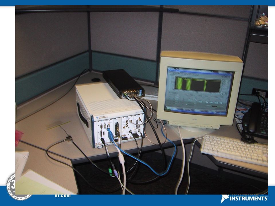
PXI RFID Tester Connectivity

47
HF RFID Antenna

48
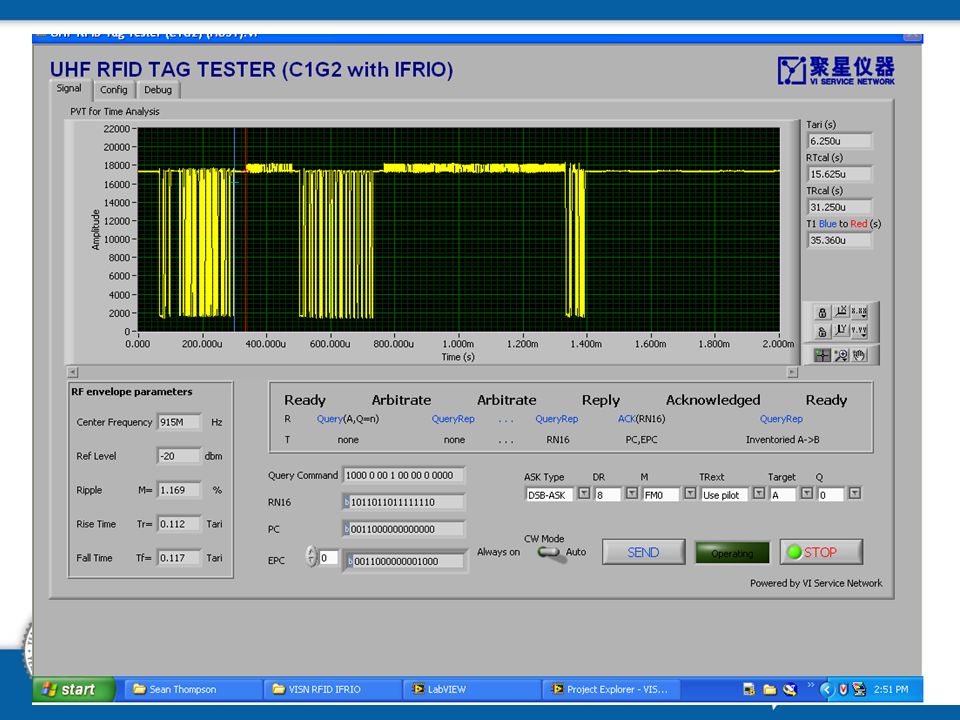
PXI HF/UHF RFID Tester

52
ZigBee Transmitter Testing and Analysis
National Instruments Leadership Seminar April, 2002 ZigBee Transmitter Testing and Analysis RF Measurements Power Spectral Density Occupied Bandwidth Power in Upper and Lower Bands Power in band (total power) Baseband Measurements IQ Plots Error Vector Magnitude (EVM) Constellation diagram Eye Diagram CCDF Data bits Analyzer is Capable of capturing signals, performing symbol synchronization, frequency synchronization and neutralizing front end non idealities Real time analysis of transmitter design by providing various RF and Baseband Measurements. Making measurements: Measuring Error Vector Magnitude (EVM) Measures modulation accuracy of transmitter Measurement impacted by phase noise from oscillator (phase jitter in time domain) NI RF Hardware provide frequency stability/accuracy in ppb range Baseband Measurements : IQ Plots have the foll plots for detailed analysis of the signal I plot IQ Phase Plot IQ Magnitude plot Extensive Graphical capabilities User defined plot color User defined style of lines Zoom Markers Auto Scale for better viewing of PSD and CCDF curve Display Parameters Frequency Offset Frame Length The Analyzer is capable of capturing signals, performing symbol synchronization, frequency synchronization and neutralizing front end non idealities. The receiver performs EVM calculation as per IEEE /ZigBee specifications. Detects automatically : provides a LED indication of Preamble Detection Packet Detection SFD detection National Instruments CONFIDENTIAL
 Baseband Measurements. IQ Plots. Error Vector Magnitude (EVM) Constellation diagram. Eye Diagram. CCDF. Data bits. Analyzer is Capable of capturing signals, performing symbol synchronization, frequency synchronization and neutralizing front end non idealities. Real time analysis of transmitter design by providing various RF and Baseband Measurements. Making measurements: Measuring Error Vector Magnitude (EVM) Measures modulation accuracy of transmitter. Measurement impacted by phase noise from oscillator (phase jitter in time domain) NI RF Hardware provide frequency stability/accuracy in ppb range. Baseband Measurements : IQ Plots have the foll plots for detailed analysis of the signal. I plot. IQ Phase Plot. IQ Magnitude plot. Extensive Graphical capabilities. User defined plot color. User defined style of lines. Zoom. Markers. Auto Scale for better viewing of PSD and CCDF curve. Display Parameters. Frequency Offset. Frame Length. The Analyzer is capable of capturing signals, performing symbol synchronization, frequency synchronization and neutralizing front end non idealities. The receiver performs EVM calculation as per IEEE /ZigBee specifications. Detects automatically : provides a LED indication of. Preamble Detection. Packet Detection. SFD detection. National Instruments CONFIDENTIAL.")
53
National Instruments Leadership Seminar
April, 2002 Signal Analysis Set Up Signal Analysis setup to test and analyze the transmitter characteristics of IEEE / ZigBee device System Requirements System Memory: Minimum 512 MB; recommended 1GB Disk Space: 100 MB OS: Windows 2000/XP NI-PXI 5660 RF Signal Analyser NI PXI 5600 (Downconvertor) NI PXI 5620 (Digitizer) Drivers : NI PXI RFSA 5660 Ver 1.5 LabVIEW Runtime Engine 7.1 National Instruments CONFIDENTIAL
 NI PXI 5620 (Digitizer) Drivers : NI PXI RFSA 5660 Ver 1.5. LabVIEW Runtime Engine 7.1. National Instruments CONFIDENTIAL.")
54
ZigBee Receiver Testing and Analysis
National Instruments Leadership Seminar April, 2002 ZigBee Receiver Testing and Analysis Measurements IQ Plot ( First 100 Samples) Complete IQ Plot Constellation (Before & After Pulse Shaping) Power Spectrum plot Eye Diagram Data patterns – 5 types Mode of Transmission Continuous mode Burst mode Frame Types Data Frame Beacon Frame MAC Command Frame Acknowledgement Frame Testing Wireless Receivers requires a “golden transmitter”, that generates data as per the standard requirements Rx components Golden transmitter: NI/SeaSolve test-bench covers the receiver chain in one measurement power spectrum, data rate, EVM etc Sensitivity – ensures that the Rx can pick up the signals and receive them at a sufficient strength. Selectivity – parameter which determines the Rx ability to pick the desired signal from the ones around it. MAC parameters: To perform a proper test of receiver characteristics (such as PER, etc) there must first be the means to transmit multiple packets, introduce noise and interference signals (impairments) etc. Can configure the type of frames transmitted, destination address, source address, and various other MAC related parameters Ability: NI Hardware provide features that enable burst transmission, bandwidth adjustments, power levels, and channel configurations. Data transmission options: Data mode, data rates, data lengths,power levels, etc. Data patterns User defined Predefined Text PRBS User defined MSDU Payload Mode of Transmission Continuous mode transmission Modulated Spectrum Unmodulated Carrier Burst mode transmission Packet transmission MAC Frames Supported Data Frame Beacon Frame MAC Command Frame Association request Association response Disassociation notification Data request PAN ID conflict notification Orphan notification Beacon request Coordinator realignment GTS request Acknowledgement Frame Configurations Configure Delay between packets Configure output power level Configure the channel Enable/Disable Impairments Configuration Configure as an alternate PAN Configure to receive Power From AC pains Configure receiver to work even in Idle status Configure Acknowledgement Request Configure transmissions to Inter or Intra PAN Configure addressing modes as 16 bit or 64 bit Configure Frame Sequence number Configure Frame Security National Instruments CONFIDENTIAL
 Complete IQ Plot. Constellation (Before & After Pulse Shaping) Power Spectrum plot. Eye Diagram. Data patterns – 5 types. Mode of Transmission. Continuous mode. Burst mode. Frame Types. Data Frame. Beacon Frame. MAC Command Frame. Acknowledgement Frame. Testing Wireless Receivers requires a golden transmitter , that generates data as per the standard requirements. Rx components. Golden transmitter: NI/SeaSolve test-bench covers the receiver chain in one measurement. power spectrum, data rate, EVM etc. Sensitivity – ensures that the Rx can pick up the signals and receive them at a sufficient strength. Selectivity – parameter which determines the Rx ability to pick the desired signal from the ones around it. MAC parameters: To perform a proper test of receiver characteristics (such as PER, etc) there must first be the means to transmit multiple packets, introduce noise and interference signals (impairments) etc. Can configure the type of frames transmitted, destination address, source address, and various other MAC related parameters. Ability: NI Hardware provide features that enable burst transmission, bandwidth adjustments, power levels, and channel configurations. Data transmission options: Data mode, data rates, data lengths,power levels, etc. Data patterns. User defined. Predefined. Text. PRBS. User defined MSDU Payload. Mode of Transmission. Continuous mode transmission. Modulated Spectrum. Unmodulated Carrier. Burst mode transmission. Packet transmission. MAC Frames Supported. Data Frame. Beacon Frame. MAC Command Frame. Association request. Association response. Disassociation notification. Data request. PAN ID conflict notification. Orphan notification. Beacon request. Coordinator realignment. GTS request. Acknowledgement Frame. Configurations. Configure Delay between packets. Configure output power level. Configure the channel. Enable/Disable Impairments Configuration. Configure as an alternate PAN. Configure to receive Power From AC pains. Configure receiver to work even in Idle status. Configure Acknowledgement Request. Configure transmissions to Inter or Intra PAN. Configure addressing modes as 16 bit or 64 bit. Configure Frame Sequence number. Configure Frame Security. National Instruments CONFIDENTIAL.")
55
Signal Generation Set Up
National Instruments Leadership Seminar April, 2002 Signal Generation Set Up Signal generation setup to test and analyze the receiver characteristics of IEEE / ZigBee device System Requirements System Memory: Minimum 512 MB, recommended 1GB Disk Space: 100 MB OS: Windows 2000/XP NI-PXI 5670 RF Signal Generator NI PXI 5421 (AWG) NI PXI 5610 (Upconvertor) Driver : NI PXI 5670 RFSG ver 1.1 NI DAQ Ver 7.1 NI FGen Ver 2.2 LabVIEW Runtime Engine 7.1 National Instruments CONFIDENTIAL
 NI PXI 5610 (Upconvertor) Driver : NI PXI 5670 RFSG ver 1.1. NI DAQ Ver 7.1. NI FGen Ver 2.2. LabVIEW Runtime Engine 7.1. National Instruments CONFIDENTIAL.")
56
National Instruments Leadership Seminar
April, 2002 Conclusion LabVIEW and PXI-based modular instruments for flexible, software-defined communication design and test LabVIEW modules for RF & Communications Advanced Signal Processing Toolkit Modulation Toolkit Spectral Measurements Digital Filter Design Toolkit Although this session only introduced the basics of virtual instrumentation and a software-defined approach to RF and communications, hundreds of organizations are successfully implementing communication systems using LabVIEW and the Modulation Toolkit. LabVIEW and PXI-based modular instruments offer a flexible, software-defined approach to communication design and test. Some of the other LabVIEW modules for RF and communications include the Spectral Measurements Toolkit for signal analysis in the frequency domain, the Digital Filter Design Toolkit for implementing custom filters on signal data, as well as the Advanced Signal Processing Toolkit for hundreds of general purpose Digital Signal Processing-based functions. National Instruments CONFIDENTIAL

57
Transmitter and Receiver Tests
National Instruments Leadership Seminar April, 2002 Transmitter and Receiver Tests * - Reference to IEEE [a] Requires the transmitter to transmit unmodulated carrier. [b] Requires the DUT to provide a PER software, which decides the outcome of the test. [c], [d] Requires 2 transmitter devices, one to transmit in desired channel and the other to transmit in adjacent/alternate channel(s). + RF Signal Analyzer and Generator National Instruments CONFIDENTIAL
. + RF Signal Analyzer and Generator. National Instruments CONFIDENTIAL.")
58
National Instruments Leadership Seminar
April, 2002 Compliance Test Set Up System requirements System Memory: Minimum 512 MB; recommended 1GB Disk Space: 100 MB OS: Windows 2000/XP NI-PXI 5670 RF Signal Generator NI PXI 5421 (AWG) NI PXI 5610 (Upconvertor) Driver : NI PXI RFSG 5670 Ver 1.1 NI FGen Ver 2.2 NI-PXI 5660 RF Signal Analyser NI PXI 5600 (Downconvertor) NI PXI 5620 (Digitizer) Driver : NI PXI RFSA 5660 Ver 1.5 NI Scope Ver 2.7 NI DAQ 7.3.1 LabVIEW Runtime Engine 7.1 National Instruments CONFIDENTIAL
 NI PXI 5610 (Upconvertor) Driver : NI PXI RFSG 5670 Ver 1.1. NI FGen Ver 2.2. NI-PXI 5660 RF Signal Analyser. NI PXI 5600 (Downconvertor) NI PXI 5620 (Digitizer) Driver : NI PXI RFSA 5660 Ver 1.5. NI Scope Ver 2.7. NI DAQ LabVIEW Runtime Engine 7.1. National Instruments CONFIDENTIAL.")
Similar presentations


 UK Ultra Wide Band (UWB) Compatibility Study Andy Gowans & Bharat Dudhia UK.>")

>")

 Receivers-1 - Parameters Chelmsford.>")


訊號量測>")

>")


