Download presentation
Presentation is loading. Please wait.

1
Cadmium Zinc Telluride (CZT) Imager
Thermal Aspects of Cadmium Zinc Telluride (CZT) Imager Presented By M.K. Hingar
 Imager. Presented By. M.K. Hingar.")
2
Plan Configuration Design Inputs Design of the Detector Board
Analysis Results Radiator & Heat Pipe Design Critical Elements Conclusions

3
CONFIGURATION

4
Thermal design Inputs for CZT-Imager
Power generated by each channel of CZT ASIC 3 mW Number of channels in each CZT Module 256 Power generated by each CZT Module 768 mW Number of CZT in each quadrant 16 Power generated by each quadrant 12.3 W Number of quadrants 4 Power generated by the CZT-Imager 49.2 W Allowed temperature variation among CZTs of each quadrant 5o Allowed temperature difference among quadrants Working temperature range of the Instrument 0o to – 20o

5
TEMPERATURE DIFFERENCE BETWEEN DIFFERENT STAGES IN ONE QUADRANT
Thermal Analysis has five Steps: Transfer of heat from CZT Detector to the CZT Detector Board. Transfer of heat within the CZT Detector Board. Transfer of heat from CZT Detector Board to the Heat pipes. Transfer of heat from Heat pipes to Radiator. Radiator design. CZT DETECTOR CZT DETECTOR BOARD WITHIN CZT DETECTOR BOARD HEAT PIPE RADIATOR 5 o 4 o 5o TEMPERATURE DIFFERENCE BETWEEN DIFFERENT STAGES IN ONE QUADRANT

6
If we consider factor of safety 2, it may be about 5 o K.
Transfer of heat from CZT Detector to the CZT Detector Board q = k A ΔT Where q = Power = W, k = Thermal Conductivity of thermal epoxy = 0.08 W / cm2 oK A = Area = 4 cm2 ΔT = / (0.08 * 4) = 2.42 o K If we consider factor of safety 2, it may be about 5 o K.
 = 2.42 o K. If we consider factor of safety 2, it may be about 5 o K.")
7
Design of Detector Board
Cu-In-Cu Copper Coating

8
Coefficient of Thermal Expansion
PROPERTIES OF CIC LAMINATE Metal /Core/ Metal Density (g/cm3) Coefficient of Thermal Expansion (ppm/0c) Thermal Conductance W/m-0c Modulus elasticity, GPa Tensile strength, MPa x, y z 20Cu/60In/20Cu 8.45 6.0 7.7 164 22 135 12.5Cu/75In/12.5Cu 8.31 3.6 5.3 110 64 140
 Coefficient of Thermal Expansion. (ppm/0c) Thermal Conductance. W/m-0c. Modulus elasticity, GPa. Tensile strength, MPa. x, y. z. 20Cu/60In/20Cu Cu/75In/12.5Cu")
9
Transfer of heat within the CZT Detector Board
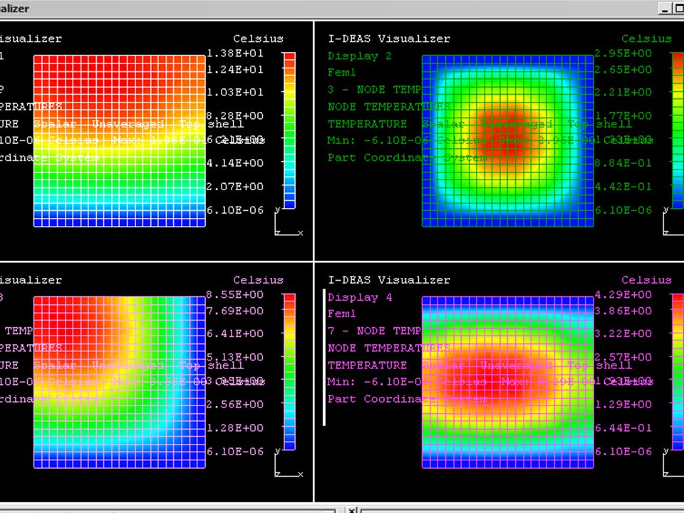
The Detector Board of 20Cu/60In/20Cu. The thickness of Detector Board is 3mm. The preliminary analysis give the maximum temperature on the Detector Board of the quadrant is about 4o.

10
Boundary Conditions Temperature at the edges of Detector Board is 0o
CZT Power (780 mW) distributed equally in 20mm X 20mm area
 distributed equally in 20mm X 20mm area.")
15
Analysis shows Heat Drain from two opposite sides of the Detector Board is necessary. Radiation losses not considered.

16
TEMPERATURE DIFFERENCE 5 o
STEPS TEMPERATURE DIFFERENCE Transfer of heat from CZT to the Detector Board 5 o Within Detector Board 4 o Detector Board to heat pipe Heat Pipe to Radiator

18
Implications of quadrants failures for thermal design
Suppose one of the quadrants fails then radiator will dissipate about 37 W (50 W ), the Radiator will have temperature of - 27o ( - 20o ). Suppose two of the quadrants fail then radiator will dissipate about 25 W (50 W), the Radiator will have temperature of - 40o ( - 20o ). Possible use of heaters to be considered after final simulation.
, the Radiator will have temperature of - 27o ( - 20o ). Suppose two of the quadrants fail then radiator will dissipate about 25 W (50 W), the Radiator will have temperature of - 40o ( - 20o ). Possible use of heaters to be considered after final simulation.")
19
CONCLUSIONS Total temperature difference is within 15 o to 20 o .
Procuring one Detector Board and measure temperature difference.

20
!!!!! THANKS !!!!!

Similar presentations