Download presentation
Presentation is loading. Please wait.

1
eQuest Quick Energy Simulation Tool

2
Main Points eQuest is a tool from the Department of Energy.
It takes the difficult interface of the more common and helpful DOE-2 and simplifies it. The learning curve with eQuest is much smaller than with the DOE-2 program. eQuest is able to model a multilevel building and all the different loads.

3
Energy Conservation eQuest has a function where Energy Efficiency Measures* can be created and manipulated to see the resulting changes to a model. eQuest also has a life cycle cost analysis tool for each EEM applied to the model. * EEM is another name for ECM, or Energy Conservation Measure

4
ESCO Analysis eQuest also has the opportunity to input several different utility bill rates and structures to find the annual cost difference for changing ESCOs. Utility rates can be complicated, and eQuest is equipped to handle the most complex billing structures.

5
eQuest Main Menu

6
Building Creation Wizard
The opening Design Development Wizard has several options: Project/Site/Utility Edit Building Shell Edit Air-Side System HW Plant Equipment

7
Project/Site/Utility
The first things that eQuest requests from the user is: Building address, Typical time table, and Utility rate structure.

8
Project/Site/Utility
The first things that eQuest requests from the user is: Building address, Typical time table, and Utility rate structure.

9
Utility Charges (both Gas and Electric)
Utility bills can be complex with a multitude of charges. eQuest allows for the user to input: A standard fixed rate A blocked charge rate Customer charges Demand rates Combined rates

10
Developing the Model The opening Design Development Wizard has several options: Project/Site/Utility Edit Building Shell Edit Air-Side System HW Plant Equipment

11
Building Shell Components
The building is constructed by first giving the program several values: Building Type, A rough estimate of the area, The number of floors, both above grade and below,

12
Building Footprint The total building area can be laid out and ploted using a simple CAD drawing Zones can also be plotted by whatever boundaries the user specifies.

13
Building Envelope Construction
Walls and roofs can be modified by selected form a list of components: Frame type and O.C. specifications Exterior finish Exterior and Interior insulation Additional insulation, commonly batt insulation The ground floor can be constructed similarily from lists of components: Exposure, such as Earth Contact or Adiabatic Space Interior finish Construction, such as slab thickness Exterior insulation Infiltration is also specified on this input screen

14
Building Envelope Construction

15
Interior Construction: Walls, Ceilings, Doors and Windows
Insulation and finishes can be specified for interior surfaces Doors: Up to three different types of doors can be specified Doors can be glass, opaque or numerous other types Once a type of door is selected, materil components can then be selected as well Frame type and width Number of doors per exterior wall This will be omitted for our design for now

16
Interior Construction: Walls, Ceilings, Doors and Windows
Up to three different types of windows can be selected Once a type of window, materials can be chosen, ranging from single pane to triple pane windows Each window can have a specific size, frame type and width Windows can be placed on exterior walls by giving a percentage of the wall that is window This will be omitted as well

17
Custom Window and Door Placement
Windows and doors in our analysis will be placed in a custom arrangement. This gives the design a wider range of window sizes than with the preset sizes. It also allows us to place the doors on the appropriate exterior surface.

18
Custom Window and Door Placement

19
Several Other Options Blinds can be applied to a set of windows or to one side of the building, as in the case of the Willet Center. Blinds can be set to partial visibility or full transparency Shades and overhangs can be applied to any window Roof skylights may be applied to different zones to help customize a building. A typical operation schedule can be given with opening and closing times.

20
Activity Areas Allocation
Areas of the building can be designated as a specific type. An area percentage is given for each type A ventilation requirement for each area Areas are then given a core or perimeter assignment. Occupancy Profile

21
Zone Group Definitions
Now that each area is defined, each area is assigned to a HVAC system and a zone This is done based on percentage of area that system covers

22
Non-HVAC End-uses Many different end-uses can be chosen at this point, both internal and external Ambient, task and exterior lighting Different equipment Pumps Motors Domestic hot water

23
Lighting Loads and Profiles
Once lighting is chosen as an end-use, a new screen and inputs becomes available Each area is given a power per area (W/sqft) of lighting An hourly profile can also be described
 of lighting. An hourly profile can also be described.")
24
Profiles

25
Developing the Model The opening Design Development Wizard has several options: Project/Site/Utility Edit Building Shell Edit Air-Side System HW Plant Equipment

26
HVAC Systems Once the HVAC system is given a name, it can begin to be defined A cooling and heating source is selected System type and assignment to different zones is selected

27
Temperatures and Air Flows
This page allows the user to select thermostat points for cooling and heating. Occupied and unoccupied Design Temperatures A minimum air flow is also given

28
Packaged Equipment This is where the heating and cooling elements are given specifications The loads of the equipment and the efficiency can both be entered (heating is requested, but not present in this screenshot)
")
29
System Fans The only system fan for our model is the supply fans that are built-in the two rooftop units Power, efficiency, fan flow and outside air ratios

30
Other Specifications Fan Schedule
Operating times during occupancy Night time run option Continuous run time or intermittent HVAC Zone Heating, Vents and Economizers Zone heating for the exhibit is baseboard heating There are no vents in our model An economizer can be selected to run with the RTU to help minimize energy costs

31
Developing the Model The opening Design Development Wizard has several options: Project/Site/Utility Edit Building Shell Edit Air-Side System HW Plant Equipment

32
Heating Primary Equipment
The heating system type is first selected Number of boilers and pumps The configuration The boiler specifications can then be selected.

33
HW System Control and Schedule
The maximum and minimum set temperatures for the boilers can be selected here Schedules for typical run time for the boilers are also given

34
Now that the construction of the model is done…

35
eQuest Main Menu

36
Energy Efficiency Wizard
The EEM wizard is used by selecting a component to adjust, such as wall insulation The program also includes a Life Cycle Cost analysis

37
Energy Efficiency Wizard
The EEM Run Details wizard allows the user to change the specification, in this case the insulation values of the wall

38
eQuest Main Menu

39
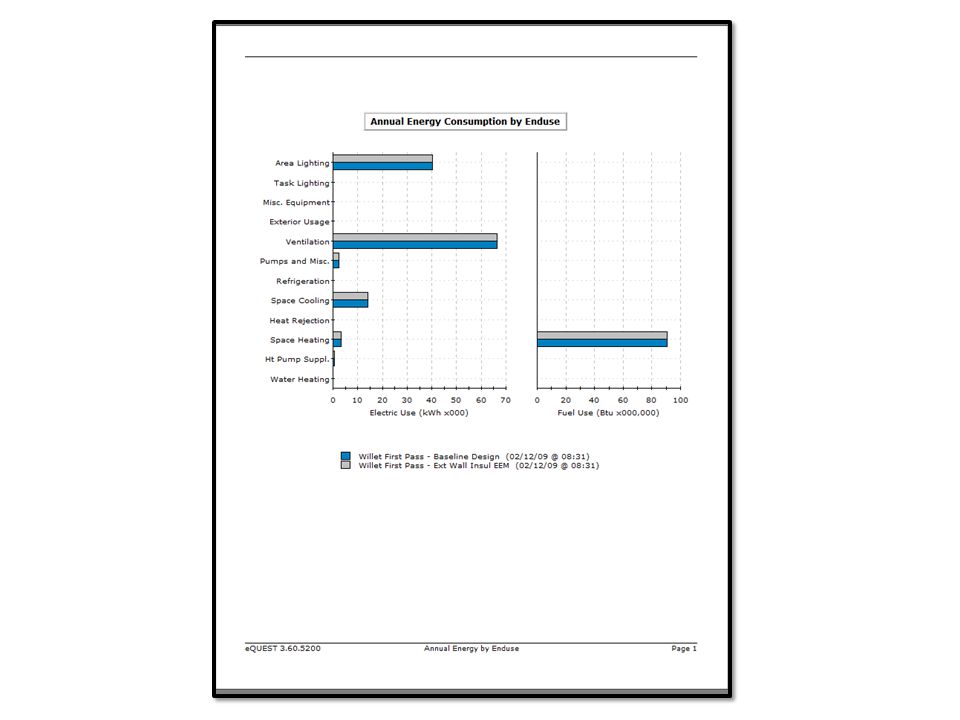
Simulated Building Performance
The program is equipped to handle multiple EEMs and a baseline. It is able to calculate daily values for energy consumption based on the building and the HVAC system inputs. It downloads weather data history from the internet. Once the simulation is performed, several reports are available

Similar presentations


;>")


>")


 Fenestration How much is optimum for the building? What should the form of the.>")
 van Dijk, Senior Scientist at Netherlands Organisation.>")


