Download presentation
Presentation is loading. Please wait.

1
Facility Wiring TDR

2
Overview zGuided - wire zUnguided - wireless zCharacteristics and quality determined by medium and signal zFor guided, the medium is more important zFor unguided, the bandwidth produced by the antenna is more important zKey concerns are data rate and distance

3
Design Factors zBandwidth yHigher bandwidth gives higher data rate zTransmission impairments yAttenuation zInterference zNumber of receivers yIn guided media yMore receivers (multi-point) introduce more attenuation
 introduce more attenuation")
4
Wiring Closet zOrderly Cable Layout zCan include all of the following: yNetwork equipment xFiber optic cables, CAT5 xWAN connections xLAN distribution yElectrical yVideo / Cable TV yTelephone yAlarm systems: intrusion, fire, door

5
Wiring Closet zOrderly Cable Layout Needs HELP!!!!!

6
Wiring Closet zOrderly Cable Layout

7
Wiring Closet

11
Patch Panels

12
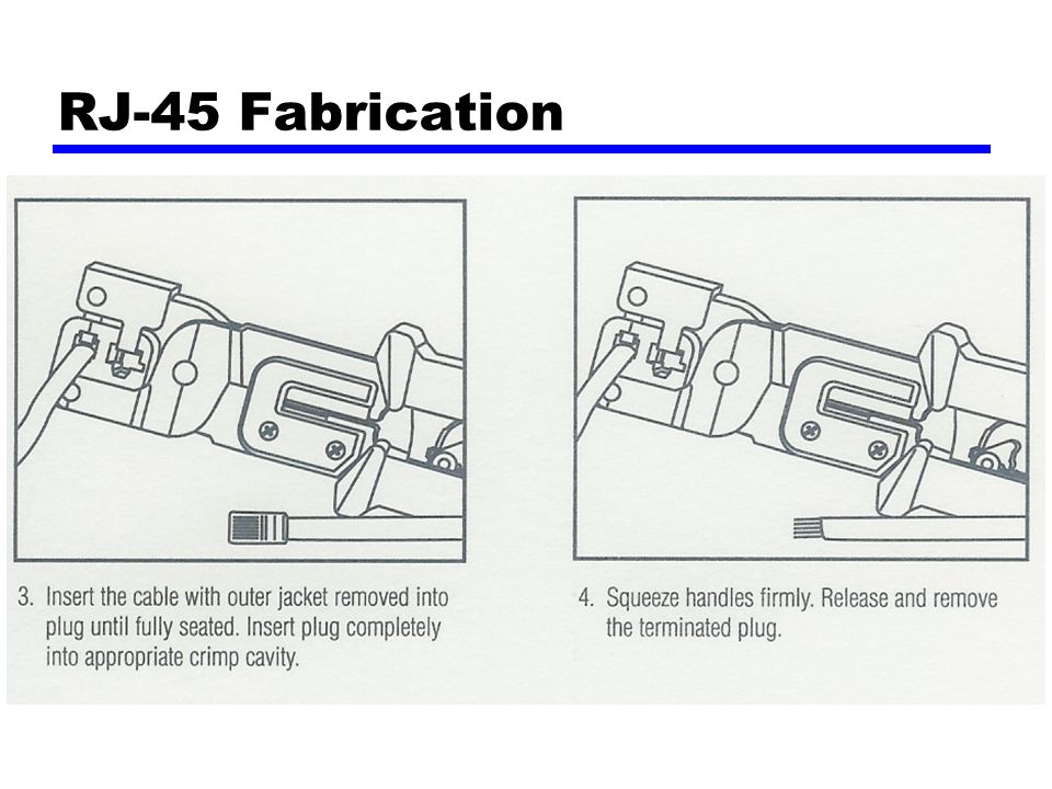
RJ-45 Fabrication

14
Time Domain Reflectometer

15
zWorks by transmitting a pulse of energy into a cable zObserving that energy as it is reflected by the system

16
Time Domain Reflectometer zBlind Spot yWidth of pulse ySpeed reduced based on media type

17
Time Domain Reflectometer zDistance vs. VOP zVelocity of Propagation – speed of light ySpeed of light in vacuum = 299,792,458 m/s ( C ) yVOP varies in different media – presented as a % yDistance pulse travels (D) = C x Time (T) D=C*T ; T = D/C yMeasured time from transmission of pulse to receipt of reflected pulse – calculate distance xRound trip delay 0.000667128 sec * 299,792,458 m/s = 200,000 xLength = 200,000 / 2 = 100,000 meters ySpeed reduced based on media type
 yVOP varies in different media – presented as a % yDistance pulse travels (D) = C x Time (T) D=C*T ; T = D/C yMeasured time from transmission of pulse to receipt of reflected pulse – calculate distance xRound trip delay sec * 299,792,458 m/s = 200,000 xLength = 200,000 / 2 = 100,000 meters ySpeed reduced based on media type.")
18
Time Domain Reflectometer zDistance - Time T = D/C

19
Time Domain Reflectometer zVOP for various media zImportant for VOP to be accurate zMeasured or Obtained from MFR

20
CABLE TYPETYPEVOP TELEPHONE 19 AWGGel-Filled68 22 AWGGel-Filled66 24 AWGGel-Filled62 26 AWGGel-Filled60 19 AWGAIR72 22 AWGAIR67 24 AWGAIR66 26 AWGAIR64 Polyethylene66 Polypropylene66 Teflon69 PIC67 Pulp72 CATV Belden Foam78S-82 Solid66 Comm/Scope(F)82 PARA I82 PARA III87 QR88 Time Domain Reflectometer zExamples of VOP
82 PARA I82 PARA III87 QR88 Time Domain Reflectometer zExamples of VOP")
21
Time Domain Reflectometer

22
A reflection with the same polarity indicates a fault with OPEN (high impedance) tendencies. The reflection shown at the second cursor is a COMPLETE OPEN.

23
A reflection with the opposite polarity indicates a fault with short (low impedance) tendencies. The reflection shown at the second cursor is a DEAD SHORT.

24
The middle reflection at the second cursor is a PARTIAL OPEN followed by a COMPLETE OPEN (end of the cable). The more severe the fault, the larger the reflection will be.

25
The middle reflection at the second cursor is a PARTIAL SHORT followed by a COMPLETE OPEN (end of the cable). The more severe the fault, the larger the reflection will be.

26
Two sections of coaxial cable with a barrel connector shown at the second cursor. The amount of reflection caused by the connector is directly proportional to the quality of the connector and connection.

27
Coaxial taps (both indoor and outdoor) will cause reflections along the waveform. The quality and value of each tap determines the amount of reflection.

28
A splitter or directional coupler can be identified although accurate measurements are difficult due to multiple reflections. The second cursor identifies the splitter. The two reflections following are the ends of each of the two segments.

29
A water soaked cable will display a waveform with a downward slope indicating the beginning of the water and an upward rise at the end of the water. Generally, the area in between the two reflections will appear "noisy".

30
Pulse Waveform 2 - Medium Pulse Width The width of the output pulse is also referred to as the blind spot or dead zone. It is more difficult to "see" a fault when it is contained within the blind spot.

31
Time Domain Reflectometer zhttp://www.tscm.com/riserbond.htmlhttp://www.tscm.com/riserbond.html zhttp://www.nuvotechnologies.com/pdf/crimping.pdfhttp://www.nuvotechnologies.com/pdf/crimping.pdf zhttp://www.pcnineoneone.com/howto/cat5diy1. htmlhttp://www.pcnineoneone.com/howto/cat5diy1. html zhttp://www.commserv.ucsb.edu/infrastructure/s tandards/history/EIA-TIA_568.asp#Four-pairhttp://www.commserv.ucsb.edu/infrastructure/s tandards/history/EIA-TIA_568.asp#Four-pair

Similar presentations


 211-8800 Ext: 5990 Email:>")


