Download presentation
Presentation is loading. Please wait.

1
Registers and Decoder

2
Four–Input 2 bit multiplexer

3
Computer Typical Arithmetic
Logic Unit

4
Internal Digital IC Faults
Malfunction in the internal circuitry-cause by one of the internal component failing or operating outside its specification Inputs or outputs shorted-input to be stuck either high or low Input output open-circuited-stuck to high or low IC output Short between 2 pins (other than ground or VCC- IC force 2 pins to be always identical

5
Internal Digital IC fault

6
Logic Probe

7
Pulse in the node

8
Logic probe used to trace shorted node

10
Computer ALU

11
Memory Terminology Memory Cell- a device or electrical circuit that can store a single bit Memory Word- A group of bits in a memory that represents information or data Byte- 8 Bit Word Nibble-a 4 bit binary number Capacity- specify how many bits can be stored in a particular memory device. Density-another term for capacity Address-this is a number that identifies location of a word in memory. Read Operation Binary word stored in a memory Write operation- a word is placed into a particular operation Access Time- memory device operating speed RAM SAM RWM

12
Continuation.. Static Memory Device-a semiconductor device that stored data permanently Dynamic Memory Device-a device that will not stored data permanently Internal Memory-computer main working memory Auxiliary Memory-Mass storage store amsiva amount of information

13
Input and output Lines perform by a memory
Select the address in memory that is being accessed for Read or Write Select either Read or Write operation to be performed Supply the input and data to be stored in the memory during a write operation Hold the output data coming from memory during a read operation Enable or (disable) memory so that it wil no respond to the address inputs and read write commands
 memory so that it wil no respond to the address inputs and read write commands.")
15
Problem 1 A certain semiconductor memory chips is specified as 2k X 8. How many words can be stored on this chips? What is the word size? How many total bits can this chips store? Given: Number of words in a memory is often 1024 = 1K 2K = 2 X 1024 = 2048 words Each word is 8 bits ( one byte) The total number of bits is therefore 2048 X 8 = 16,348 bits
 The total. number of bits is therefore X 8 = 16,348 bits.")
16
Problem 2 A certain memory has a capacity of 256K X 8.
How many data input and data input does it have? How many address lines does it have? What is its capacity in bytes?

17
Solution A) Eight of each, since the word size is eight.
B) The memory stores 256 =256 X 1024 = 262,144 words. Thus, there are 262,144 memory addresses. Since 262,144 = 2 it requires 8 bit address code to specify one of 262,144 addresses C) a byte is 8 bits, this memory has the capacity of 262,144 bytes 18
 The memory stores 256 =256 X = 262,144 words. Thus, there are 262,144 memory addresses. Since 262,144 = 2 it requires 8 bit address code to specify one of 262,144 addresses. C) a byte is 8 bits, this memory has the capacity of 262,144 bytes. 18.")
18
Read Only Memory

19
The READ operation There are 16 data words stored at 16 different address location. Example location 0011 is this data is stored in binary inside ROM

20
ROM Architecture Internal structure of a ROM IC is very complex (recommendation need not to know the details) Four basic parts of ROM Row decoder Column decoder Register array- register data that has been programmed into ROM And output buffers.

21
Rom Architecture

22
Address Decoder Determines which register in the array will be enabled to place its 8 bit data word into the bus. Example 1 What register will enabled by input address 1101? Ans. A3 A2 = 11 will activate column 3 A1 A0 = 01 will activate the row 1 select line.

23
Example 2 What input address will enable register 10?
Ans. A1 A0 = 10 and A3 A4 = 10 Therefore A3 A2 A1 A0 = 1010

24
Output buffers Data is feed into the output buffers, which will pass the data into the external data outputs provided that CS is low. If CS is High the output buffers are in high Z state and D0-D8 will be floating. Example: Intel 2708 is a MOS ROM that stores bit words. Its 1024 registers are arrange in a 64 X 16 array. In practice ROM capabilities typically range from 32 to over 1 M bytes

25
Example Describe the internal architecture of a ROM that stores 4K bytes and uses a square register array. Solution 4K is = 4 X 1024 = 4096 therefore it holds bits words. Since 4096 = 64 the register are arrange by 64 by 64 array There are 64 rows and 64 column This requires 1 of 64 decoder to decode the six address for the row select Also 1-of-64 decoder to decode the six address inputs for the column select Thus the total of 12 address inputs are required Therefore since 2 = 4096 proving that there are 4096 different address 2 12

26
Types of ROM Mask Program ROM-has its storage location written into (programmer) by the manufacturer according to customer’s specifications.
 by the manufacturer according to customer’s specifications.")
27
MROM bipolar transistor

28
Truth table

29
Cont… Programmable ROM (PROMs)
Expensive an is used in a high volume applications. Fusible links for less cost refered to as one time program. Example is 74186

30
Fusible-link

31
Cont… Erasable programmable ROM (EPROM)
Can be program by the user and it can be erased also as often desired. Once programmed, the EPROM is a nonvolatile memory that will hold its desired data indefinitely To erase the program exposed to UV light Available with a capacity of 128K X ns Example: Intel 2732 is a 4k X8 NMOS EPROM

32
EPROM

33
Truth Table

34
Cont…. Electrically Erasable PROM (EEPROM)
Retains the same floating-gate structure as the EPROM Developed product of EPROM (100 ns) Has the ability to electrically erase and rewrite individual bytes (8 bit words) in memory during the array During the write operation internal circuitry automatically erases all the cells at an address location prior to writing the new data Example: Intel K X 8 array with 13 address inputs (2 = 8292) and 8 data I/O pins 13
 Has the ability to electrically erase and rewrite individual bytes (8 bit words) in memory during the array. During the write operation internal circuitry automatically erases all the cells at an address location prior to writing the new data Example: Intel K X 8 array with 13 address inputs (2 = 8292) and 8 data I/O pins. 13.")
35
EEPROM

36
Truth Table

37
Flash Memory Non Volatile Fast read access time (120 ns)
Can be erased and can be program

38
Flash Memory

39
Table

40
28F256A Flash memory chips

41
28F256A Flash memory Chips

42
ROM Application Firmware- storage of data and program codes that must be available on power-up in microprocessor-based systems Data Tables- used in trigonometric tables Data Converter- data is expressed in one type of code and produces an output expressed in another type

43
Data Converter

44
Semiconductor RAM’s RAM-any memory address location is as easily accessible as any other.

45
RAM Architecture 1K 4K 8K 16K 64K Word sizes 1, 4, 8 bits

46
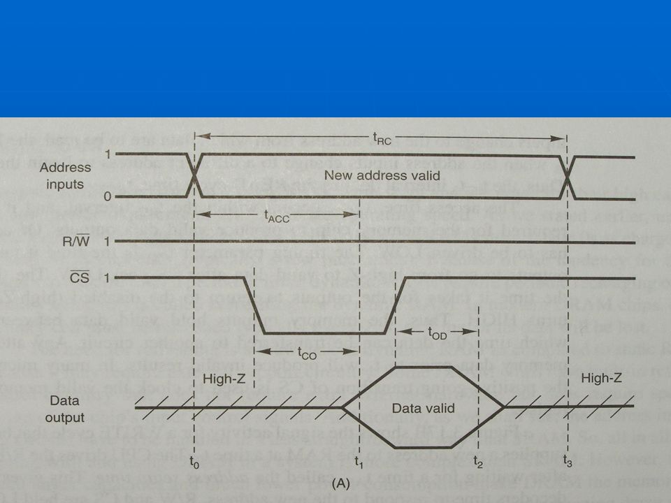
READ operation In order to read the content the RW must be 1
Chip select must be set to 0 The above combination enables the output buffers to show the selected register to appear four data output

47
WRITE Operation

48
RAM IC 2147H, MCM6206

49
NMOS Static RAM Cells

Similar presentations


>")
>")


 –Structure of diode ROM –Types of ROMs. –ROM with 2-Dimensional Decoding. –Using.>")

>")


