Download presentation
Presentation is loading. Please wait.

1
DIMENSIONING AND TOLERANCING

2
prismatic.sldasm

3
DIFFERENT TYPES OF FIT Clearance fit
Limits of size defined such that a clearance always results when mating parts are assembled Interference fit Limits of size are so prescribed that interference always results when mating parts are assembled. Transition fit Limits of size are so prescribed that either clearance or an interference may results when mating parts are assembled Line fit Limits of size are so prescribed that surface contact or clearance may result when mating parts are assembled

4
BASIC HOLE SYSTEM In the basic hole system the minimum (lower limit) hole size is taken as the basic size. Stock hole is made “first” and then shaft is made to particular type of fit (to suit the hole).
.")
5
BASIC SHAFT SYSTEM In the basic shaft system the maximum (upper limit) shaft size is taken as the basic size. Stock shaft is created “first” and hole is made to particular type of fit (to suit the shaft).
.")
6
IDENTIFY FIT SYSTEM Basic shaft or basic hole?
In the basic hole system the minimum (lower limit) hole size is taken as the basic size. Stock hole is made “first” and then shaft is made to particular type of fit (to suit the hole). In the basic shaft system the maximum (upper limit) shaft size is taken as the basic size. Stock shaft is created “first” and hole is made to particular type of fit (to suit the shaft).
 hole size is taken as the basic size. Stock hole is made first and then shaft is made to particular type of fit (to suit the hole). In the basic shaft system the maximum (upper limit) shaft size is taken as the basic size. Stock shaft is created first and hole is made to particular type of fit (to suit the shaft).")
7
IDENTIFY FIT SYSTEM “Shaft” “Hole” - = - = What type of fit is this?

8
IDENTIFY FIT SYSTEM

9
IDENTIFY FIT SYSTEM Basic hole More commonly used Basic shaft
Less commonly used

10
Shown are limit tolerances
IDENTIFY FIT SYSTEM Shown are limit tolerances

11
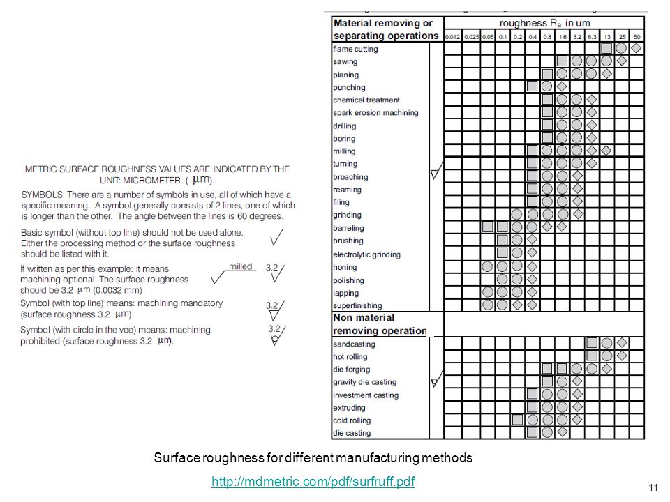
Surface roughness for different manufacturing methods
13
Φ Basic hole fits

14
Φ Basic shaft fits

15
Description of preferred fits

16
ANSI PREFERRED HOLE BASIS METRIC CLEARANCE FITS
Pages 312, 313, 314, 315 ANSI PREFERRED SHAFT BASIS METRIC CLEARANCE FITS Pages 316, 317, 318, 319 Engineering Design Graphics James Leake Jacob Borgerson

17
cylindrical_metric.sldasm
Nominal diameter 25mm Btw. what is wrong with this assembly? cylindrical_metric.sldasm

18
Loose running fit for nominal diameter 25mm preferred hole basic

19
Free running fit for nominal diameter 25mm preferred hole basic

20
Close running fit for nominal diameter 25mm preferred hole basic

21
Sliding fit for nominal diameter 25mm preferred hole basic

22
Locational transition fit for nominal diameter 25mm preferred hole basic

23
Locational transition fit for nominal diameter 25mm preferred hole basic

24
Locational interference fit for nominal diameter 25mm preferred hole basic

25
Medium drive fit for nominal diameter 25mm preferred hole basic

26
Force fit for nominal diameter 25mm preferred hole basic

27
Hole is always the same: H7
We obtained the desired fit by changing shaft tolerance

Similar presentations


