Download presentation
Presentation is loading. Please wait.

1
(CSC 102) Discrete Structures Lecture 5
 Discrete Structures Lecture 5")
2
Previous Lecture Summery
Basic Logic gates Constructing Circuits using logic gates Designing Circuits for given Inputs/outputs Equivalent Circuits Reductions of circuits

3
Applications of Logic

4
Todays Lecture Outline
NAND and NOR Gates Basics of Boolean Algebra Decimal and Binary numbers Half Adders Circuits using Half adders Full adder circuits Parallel Adder Circuits

5
Equivalent Circuits [(P∧ ∼Q) ∨ (P ∧ Q)] ∧ Q
Following is the circuit representations of the statement [(P∧ ∼Q) ∨ (P ∧ Q)] ∧ Q
![Equivalent Circuits [(P∧ ∼Q) ∨ (P ∧ Q)] ∧ Q](http://slideplayer.com/slide/1653372/7/images/5/Equivalent+Circuits+%5B%28P%E2%88%A7+%E2%88%BCQ%29+%E2%88%A8+%28P+%E2%88%A7+Q%29%5D+%E2%88%A7+Q.jpg "Following is the circuit representations of the statement. [(P∧ ∼Q) ∨ (P ∧ Q)] ∧ Q.")
6
Equivalent Circuits [(P ∧ ∼Q) ∨ (P ∧ Q)] ∧ Q ≡ (P ∧ (∼Q ∨ Q)) ∧ Q ; by the distributive law ≡ (P ∧ (Q ∨ ∼Q)) ∧ Q ; by the commutative law for ∨ ≡ (P ∧ t) ∧ Q ; by the negation law ≡ P ∧ Q ; by the identity law.
 ∨ (P ∧ Q)] ∧ Q ≡ (P ∧ (∼Q ∨ Q)) ∧ Q ; by the distributive law ≡ (P ∧ (Q ∨ ∼Q)) ∧ Q ; by the commutative law for ∨ ≡ (P ∧ t) ∧ Q ; by the negation law ≡ P ∧ Q ; by the identity law.")
7
Equivalent Circuits Thus the two circuits are logically equivalent.

8
Equivalent Circuits Find the Boolean expressions for the circuits and show that they are logically equivalent

9
Equivalent Circuits Find the Boolean expressions for the circuits and show that they are logically equivalent

10
P | Q ≡ ∼(P ∧ Q) and P ↓ Q ≡ ∼(P ∨ Q).
NAND and NOR Gates Another way to simplify a circuit is to find an equivalent circuit that uses the least number of different kinds of logic gates. Two gates not previously introduced are useful for this: NAND-gate and NOR-gate. A NAND-gate is a single gate that acts like an AND-gate followed by a NOT-gate. A NOR-gate acts like an OR-gate followed by a NOT-gate. Thus the output signal of a NAND-gate is 0 when, and only when, both input signals are 1, and the output signal for a NOR-gate is 1 when, and only when, both input signals are 0. The logical symbols corresponding to these gates are | (for NAND) and ↓ (for NOR), where | is called a Sheffer stroke and ↓ is called a Peirce arrow. Thus P | Q ≡ ∼(P ∧ Q) and P ↓ Q ≡ ∼(P ∨ Q).
 and ↓ (for NOR), where | is called a Sheffer stroke and ↓ is called a Peirce arrow. Thus. P | Q ≡ ∼(P ∧ Q) and P ↓ Q ≡ ∼(P ∨ Q).")
11
NAND and NOR Gates

12
NAND and NOR Gates It can be shown that any Boolean expression is equivalent to one written entirely with Sheffer strokes or entirely with Peirce arrows. Thus any digital logic circuit is equivalent to one that uses only NAND-gates or only NOR-gates.

13
Rewriting Expressions Using the Sheffer Stroke
Use the definition of Sheffer stroke to show that a. ∼P ≡ P | P b. P ∨ Q ≡ (P | P) | (Q | Q).
 | (Q | Q).")
14
Rewriting Expressions Using the Peirce Arrow
Show that the following logical equivalences hold for the Peirce arrow ↓, where P ↓ Q ≡ ∼(P ∨ Q). a. ∼P ≡ P ↓ P b. P ∨ Q ≡ (P ↓ Q) ↓ (P ↓ Q) c. P ∧ Q ≡ (P ↓ P) ↓ (Q ↓ Q) b. (P ↓ Q) ↓ (P ↓ Q) ≡ ∼(P ↓ Q) by part (a) ≡ ∼[∼(P ∨ Q)] by definition of ↓ ≡ P ∨ Q by the double negative law
. a. ∼P ≡ P ↓ P. b. P ∨ Q ≡ (P ↓ Q) ↓ (P ↓ Q) c. P ∧ Q ≡ (P ↓ P) ↓ (Q ↓ Q) b. (P ↓ Q) ↓ (P ↓ Q) ≡ ∼(P ↓ Q) by part (a) ≡ ∼[∼(P ∨ Q)] by definition of ↓ ≡ P ∨ Q by the double negative law.")
15
Boolean Algebra d ·10n Decimal representations
6152 = 6* * *10 + 2*1 = 6* * * *100. More generally, decimal notation is based on the fact that any positive integer can be written uniquely as a sum of products of the form d ·10n where each n is a nonnegative integer and each d is one of the decimal digits 0, 1, 2, 3, 4, 5, 6, 7, 8, or 9. The word decimal comes from the Latin root deci, meaning “ten.”

16
Boolean Algebra Converting decimal to binary representations
27 = = 1·24 + 1·23 + 0·22 + 1·21 + 1·20.

17
Boolean Algebra Any integer can be represented uniquely as a sum of products of the form d ·2n where each n is an integer and each d is one of the binary digits (or bits) 0 or 1.
 0 or 1.")
18
Converting binary to decimal
Represent in decimal notation.

19
Addition in Binary Notation
Add and 1112 using binary notation. Solution: Because 210 = 102 and 110 = 12, the translation of = 210 to binary notation is It follows that adding two 1’s together results in a carry of 1 when binary notation is used. Adding three 1’s together also results in a carry of 1 since 310 = 112 (“one one base two”).
.")
20
Addition in Binary Notation
Thus the addition can be performed as follows:

21
Boolean Algebra Just like Boolean logic, variables can only be 1 or 0, instead of true/false Not ~0 = 1 ~1 = 0 Or is used as a plus And is used as a multiplication 0+0 = * 0 = 0 0+1= * 1 = 0 1+0= * 0 = 0 1+1= ? * 1 = 1

22
Half Adder Consider adding two 1-bit binary numbers x and y
0+0 = 0 0+1 = 1 1+0 = 1 1+1 = 10 Carry is x AND y Sum is x XOR y The circuit to compute this is called a half-adder.

23
Circuit of Half Adder Sum = x XOR y Carry = x AND y

24
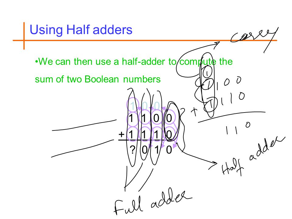
Using Half adders We can then use a half-adder to compute the sum of two Boolean numbers 1 ? 1
25
How to fix that We need to create an adder that can take a carry bit as an additional input Inputs: x, y, carry in Outputs: sum, carry out This is called a full adder Will add x and y with a half-adder Will add the sum of that to the carry in What about the carry out? It’s 1 if either (or both): x+y = 10 x+y = 01 and carry in = 1
: x+y = 10. x+y = 01 and carry in = 1.")
26
The Full adder

27
Parallel Adder Circuits
Two full-adders and one half-adder can be used together to build a circuit that will add two three-digit binary numbers PQR and STU to obtain the sum WXYZ. Such a circuit is called a parallel adder. Parallel adders can be constructed to add binary numbers of any finite length.

28
The Full adder The full circuitry of the full adder

29
Lecture summary Basic Logic gates Circuits using logic gates
Boolean Algebra Adders (Half and Full)
")
Similar presentations


>")


