Download presentation
Presentation is loading. Please wait.

1
A Technical Review of Proper Masonry Detailing
Matthew A. Dettman, P.E.

2
Overview Water Penetration Resistance Differential Movement
Wall Systems Flashing and Weep holes Coatings Differential Movement Cracking Movement Joints

3
Problems related to water penetration
Water entry into interior Efflorescence Spalling Corrosion Reduced insulating capacity Staining / Mold / Mildew

4
Keys to Providing Water Penetration Resistance
Quality Materials Good Construction Proper detailing Maintenance

5
Keys to Providing Water Penetration Resistance
Quality Materials Good Construction Proper detailing Maintenance

6
Three Basic Wall Types Drainage Wall Barrier Wall Single Wythe Wall

7
Drainage Wall

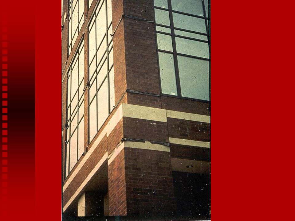
8
Drainage Wall Water travels down back side of outer wythe, collected on flashing, and channeled to exterior through weep holes Examples: Cavity walls Masonry veneer walls Rain screen walls

9
Drainage Walls Requirements
2 to 4 ½ inch clear cavity Flashing and weep holes to channel out excessive water

10
Rain Screen Wall Equalizes pressure within cavity
Vents at top and bottom of wall or panel Flashing and weep holes Compartmentalized Allows for ventilation and evaporation

11
Barrier Wall Collar joint between wythes acts a barrier to moisture along with the thickness of the wall Examples Brick and Block Composite Wall

12
Barrier Wall Voids allow water penetration
Must be filled solid with mortar or grout

13
Single Wythe Walls

14
Single Wythe Masonry units with coating or integral water repellent
Mortar with integral water repellent Through-wall flashing Weep Holes Vents

15
Flashing Details Locations Placement

16
Flashing Locations base of wall sills heads of windows at shelf angles
copings lower wall/ higher roof intersection other discontinuities in air space

21
Good Flashing Detail

22
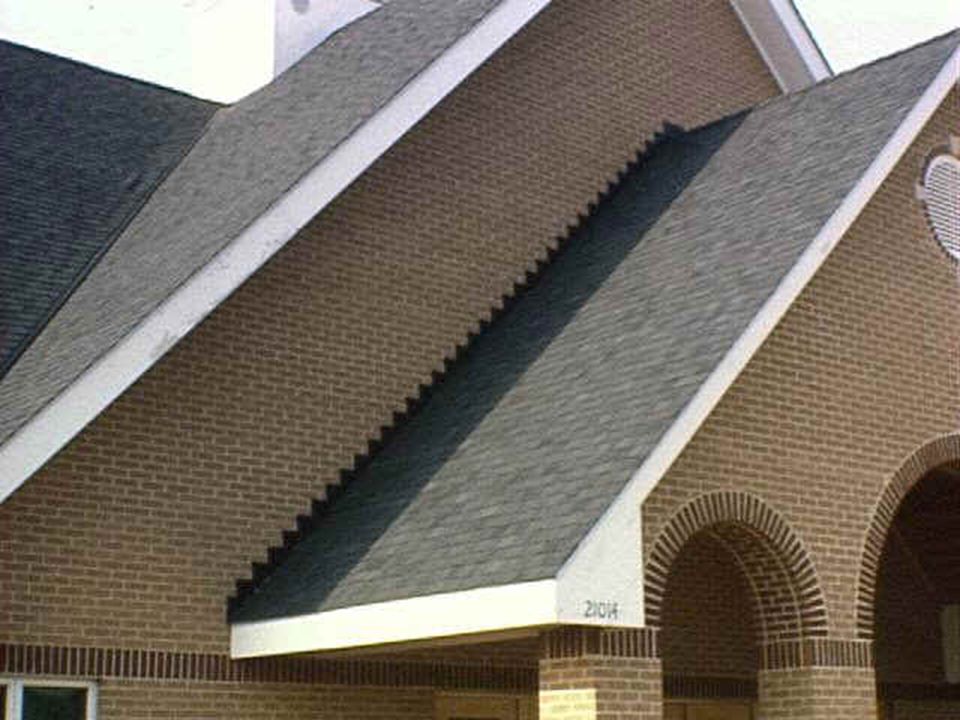
Poor Detail

23
Drip Edge

25
SS Drip Edge

26
Shelf Angles

27
Flashing Single Wythe Walls

28
Flashing with Shear Transfer

29
Flashing Reinforced Wall

30
End Dams

31
Flashing Laps

32
Drainage Materials

33
Weep Holes

34
Weep Tubes

35
Vent Weep Holes

36
Rope Wicks

37
Flashing Materials Sheet Metal Composites Plastic and Rubber Compounds

38
Sheet Metals Material Advantages Disadvantages Hard to solder and form
Damaged by excessive flexing and can stain Difficult to solder, corrodes early in acidic and salty air Stainless Steel Cold-Rolled Copper Galvanized Steel Durable, non staining Durable Easy to paint and durable Stainless steel is technically any of a large and complex group of corrosion resistant iron chromium alloys possessing excellent weather and chemical resisting properties. Preformed sections must be properly sized so that modification on the site is minimal. Typical: Type 304 stainless steel with a minimum thickness of in. (0.25 mm). Lapped sections must be soldered. Stainless steel drip edges used in combination with other flashing materials also works well. Copper is a non-ferrous metal with good ductility. Like stainless steel, it also possesses excellent weather and chemical resistant properties. Preformed sections are easier to modify in the field. Be careful of green patina stains! Galvanized steel is less expensive than stainless, but is more subject to attack from salts and acids. The galvanized coating may also crack at bends, lowering the corrosion resistance. As with stainless, hard to solder laps.
. Lapped sections must be soldered. Stainless steel drip edges used in combination with other flashing materials also works well. Copper is a non-ferrous metal with good ductility. Like stainless steel, it also possesses excellent weather and chemical resistant properties. Preformed sections are easier to modify in the field. Be careful of green patina stains! Galvanized steel is less expensive than stainless, but is more subject to attack from salts and acids. The galvanized coating may also crack at bends, lowering the corrosion resistance. As with stainless, hard to solder laps.")
39
Composites Material Advantages Disadvantages
Difficult to solder, damaged by excessive flexing, metal drip edge suggested Degrades in UV light, more easily torn than metal Lead-coated copper Copper laminates Flexible, durable, non-staining Easy to form Some companies provide flashings that have combined metals and plastics. Copper composites are popular since they combine the durability and malleability of copper with non-staining characteristics of the plastic coating. Composites containing aluminum should be avoided.

40
Plastics and Rubber Compounds
Material Advantages Disadvantages Flexible, easy to form, non-staining Fully adhered, separate lap adhesive not needed, self healing, flexible, easy to form and join Easy to form and join, non-staining, low cost Aesthetics if not used with a metal drip edge, full support recommended Full support required, degrades in UV light, metal drip edge required Easily damaged, full support required, metal drip edge required, questionable durability EPDM Rubberized asphalt PVC Plastics are categorized as polymeric materials of large molecular weight, usually polyvinyl chloride (PVC) or polyethylene. Manufacturers of plastic flashings should be consulted for documentation establishing the longevity of the plastic in a caustic environment (pH = 12.5 to 13.5), the composition of the plastic, ease of working at temperatures ranging from 20 to 100°F and ability to withstand exposure to ultraviolet light. Ethylene Propylene Diene Monomer (EPDM) is a synthetic rubber that is used as a single ply roofing membrane as well as flashing. It has better low temperature performance than PVC and will not embrittle. It offers ultraviolet light and ozone resistance and can be left exposed. Self-adhering, rubberized asphalt membranes consist of a composite of flexible plastic film for puncture and tear resistance combined with a rubberized asphalt adhesive layer. This material adheres to itself, requiring less effort to seal laps or corners which speeds installation. It also self-adhered to the substrate which prevents water form migrating under the flashing and is self-healing in the event of punctures. However, it should not be applied to damp, dirty, or dusty surfaces and has a typical lower limit installation temperature of 25 °F. Because it degrades in the presence of extended UV exposure, it should not be left exposed and requires a metal drip edge.
 or polyethylene. Manufacturers of plastic flashings should be consulted for documentation establishing the longevity of the plastic in a caustic environment (pH = 12.5 to 13.5), the composition of the plastic, ease of working at temperatures ranging from 20 to 100°F and ability to withstand exposure to ultraviolet light. Ethylene Propylene Diene Monomer (EPDM) is a synthetic rubber that is used as a single ply roofing membrane as well as flashing. It has better low temperature performance than PVC and will not embrittle. It offers ultraviolet light and ozone resistance and can be left exposed. Self-adhering, rubberized asphalt membranes consist of a composite of flexible plastic film for puncture and tear resistance combined with a rubberized asphalt adhesive layer. This material adheres to itself, requiring less effort to seal laps or corners which speeds installation. It also self-adhered to the substrate which prevents water form migrating under the flashing and is self-healing in the event of punctures. However, it should not be applied to damp, dirty, or dusty surfaces and has a typical lower limit installation temperature of 25 °F. Because it degrades in the presence of extended UV exposure, it should not be left exposed and requires a metal drip edge.")
41
Bldg felt and poly sheeting

42
Colorless Coatings Used for a variety of reasons
Recommended for Concrete Masonry Questionable for Clay Masonry

43
Possible Dangers Water can still penetrate Could cause spalling
If efflorescence occurs under coating, it may be impossible to remove Recoating will be necessary

44
Coating Types Colorless Coatings Paints

45
Colorless Coatings Penetrating Film-forming Silanes Siloxanes Acrylics
Stearates

46
Coating Types Paints Cement based Latex Alkyd Oil-based Paints

47
Differential Movement
Movements Temperature Movement Moisture Movement Elastic Deformation Movement Joints Design Placement

48
Causes of Cracking Differential Movement Restraint Settlement
Elastic Deformations Creep

49
Types of Movement

50
Temperature Movement Coefficient of Thermal Expansion
Brick = 3.6 x 10⁻⁶ Concrete Masonry = 4.3 x 10⁻⁶ Aluminum = 12.8 x 10⁻⁶ Steel = 6.5 x 10⁻⁶

51
Moisture Movement Brick - irreversible expansion
Concrete masonry – drying shrinkage and carbonation

52
Types of Movement Joints
Expansion Joint - Brick Masonry Control Joint - Concrete Masonry Building Joint - Structures

53
Expansion Joint Used in Clay Masonry
Used to separate brick into sections so cracking will not occur Horizontal / Vertical Entire joint is unobstructed and formed from a highly elastic, continuous material

54
Types of Expansion Joints (Details)
")
55
Expansion Joint

56
Typical Spacing and Locations of Expansion Joints
Long Walls Corners Setbacks & Offsets Parapet walls Beneath shelf angles

57
Expansion Joints at Corners

58
Horizontal Expansion Joint

59
False Horizontal EJ

60
Hiding Expansion Joints

61
Control Joint Used in Concrete Masonry
Relieve horizontal tensile stresses Reduce restraint and permit longitudinal movement Separate dissimilar materials

62
Types of Control Joints
Pre-formed gasket Formed paper Special shape units

63
Pre-formed Gasket

64
Formed Paper (also known as Michigan Joint)
")
65
Special Shape Unit

66
Joint Reinforcement at CJ

67
Bond Beams Do not cut bond beam reinforcement unless specifically indicated on the plans

68
Control Joint Locations

69
Control Joint Spacing Two methods: Empirical Engineered
based on historical performance Engineered based on a crack control coefficient

70
Empirical Control Joint Criteria
Spacing for above grade exposed concrete masonry walls Distance between joints is the lesser of: Length to height ratio or 1 ½ feet Notes: Based on horizontal reinforcement of in.2/ft Applies to both Type I and Type II units Can be modified based on local experience

71
Engineered Crack Control Criteria
Criteria for Controlling Cracking in Reinforced Concrete Masonry Walls Crack Control Coefficient in./in. (mm/mm) ________________ __________ __________ ___ Maximum wall _length, ft (m)_________25 (7.62)__20 (6.10) panel dimensions_ length/height ratio_ _____2 ½ ______2___ Min. horizontal reinf. ratio As/An Notes: As = cross-sectional area of steel, in2/ft (mm2/m) An = net cross-sectional area of masonry, in2/ft (mm2/m)
 ________________ __________ __________ ___ Maximum wall _length, ft (m)_________25 (7.62)__20 (6.10) panel dimensions_ length/height ratio_ _____2 ½ ______2___. Min. horizontal reinf. ratio As/An Notes: As = cross-sectional area of steel, in2/ft (mm2/m) An = net cross-sectional area of masonry, in2/ft (mm2/m)")
72
Engineered Crack Control Criteria (cont.)
Notes: Need not apply if As/An > see Table 4. See Table 3 for As/An = minimum requirement. Minimum reinforcement ratio need not apply if length is < ½ maximum length shown in table. CCC’s less than may be available in some areas and spacing should be adjusted accordingly. Control joint spacing may be adjusted up or down based on local experience.

73
Table 3—Maximum Spacing of Hor. Reinf. for A > 0.0007A
1 Wall thick in. Maximum spacing of horizontal reinforcement, in. (mm) Reinforcement size #5 #4 #3 4x 3/16 4 x 8 gage 4 x 9 2x 2 x 8 2 x 9 Ungrouted or partially grouted walls 6 144 128 64 72 56 48 40 24 8 96 32 16 10 136 80 12 120 1. A includes cross-sectional area of grout in bond beams.
 Reinforcement size. #5. #4. #3. 4x. 3/16. 4 x 8. gage. 4 x 9. 2x. 2 x 8. 2 x 9. Ungrouted or partially grouted walls A. includes cross-sectional area of grout in bond beams.")
74
Brick and Block Together
Align Expansion Joints and Control Joints

75
Bond Breaks Use to separate bands of different masonry types

Similar presentations


, plank lap (horizontal), T1-11 ply, vinyl, fiber cement, aluminum, stucco.&>")


>")


