Download presentation
Presentation is loading. Please wait.

1
Development of Computational Model of Sport Utility Vehicle Srdan Simunovic, Gustavo Aramayo and Thomas Zacharia Computer Science and Mathematics Division Oak Ridge National Laboratory NHHTSA Project Review, October 20 1998

2
http://www-explorer.ornl.gov

3
Outline Status Modeling Approach Available Models Things to Finalize

4
Status Developed parametric finite element model of 1998 Ford Explorer XLT 4x2 Tested models –full frontal impact –frontal offset impact –frontal offset oblique impact Developed WWW-based model manipulation –WWW based model generation available 12/98

5
Related Parametric FEM Projects at ORNL Aluminum Intensive Vehicle Model Development Ultra Light Steel Auto Body

6
Aluminum Intensive Vehicle

10
ULSAB

14
Fixed FEM Mesh Model Initial FEM model was based on dirty geometry –scanned geometry was not extensively modified –regularity and connectivity of FEM mesh was enforced by direct placement of nodes on surfaces and by single FEM mesh realization Model has varying degree of FEM mesh regularity and quality –frame - high –body - low Model was tested in frontal and frontal-offset impact

15
Fixed FEM Model Features 25k Nodes, 25k Elements Relatively good results –good deformation, crash duration, acceleration –mainly due to importance of frame in impact response Model modifications not practical –regularity enforced by numerous ad-hoc constraints

16
Parametric FEM Model Objective –More FEM meshes in less time Methodology developed can be easily applied to other FEM models Want to learn more on vehicle impact simulations Have not been done yet for such complex models

17
Advantages of Parametric Model Rapid generation of crash situation-specific models Simple model modification through parameter modification Allows for investigation of convergence of simulation results Becomes possible to determine the best model for specific impact scenario

18
Disadvantages of Parametric Modeling Approach Longer initial model development time Geometry needs to be clean Software not yet available for entire process Manipulation of large number of parameters is cumbersome, therefore, model modification is usually limited to initial developers

19
Coarse FEM Mesh

20
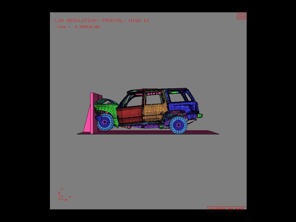
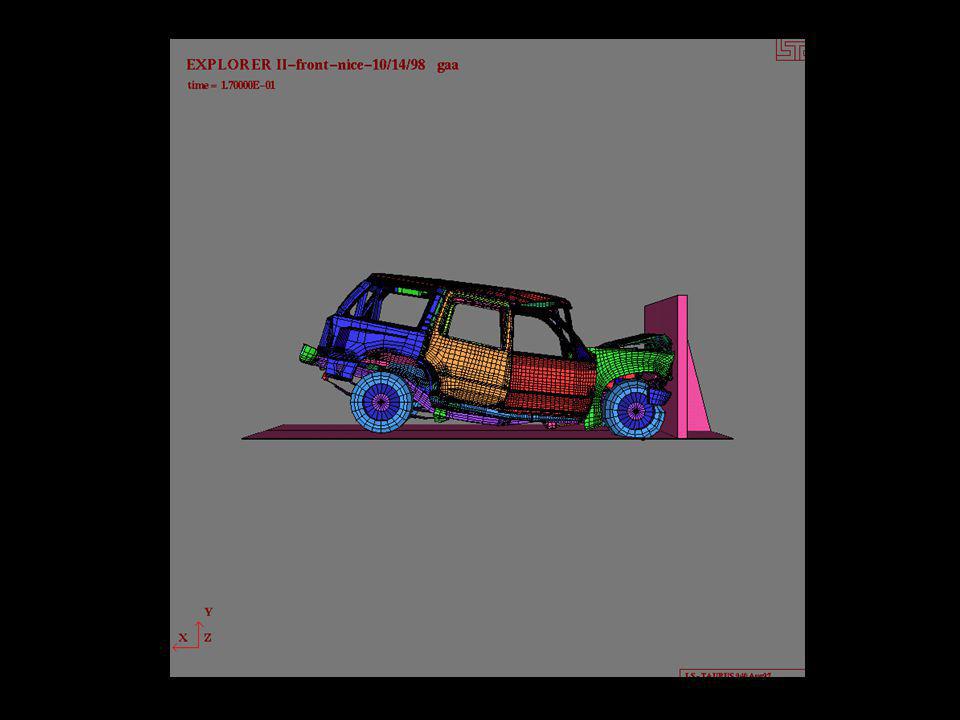
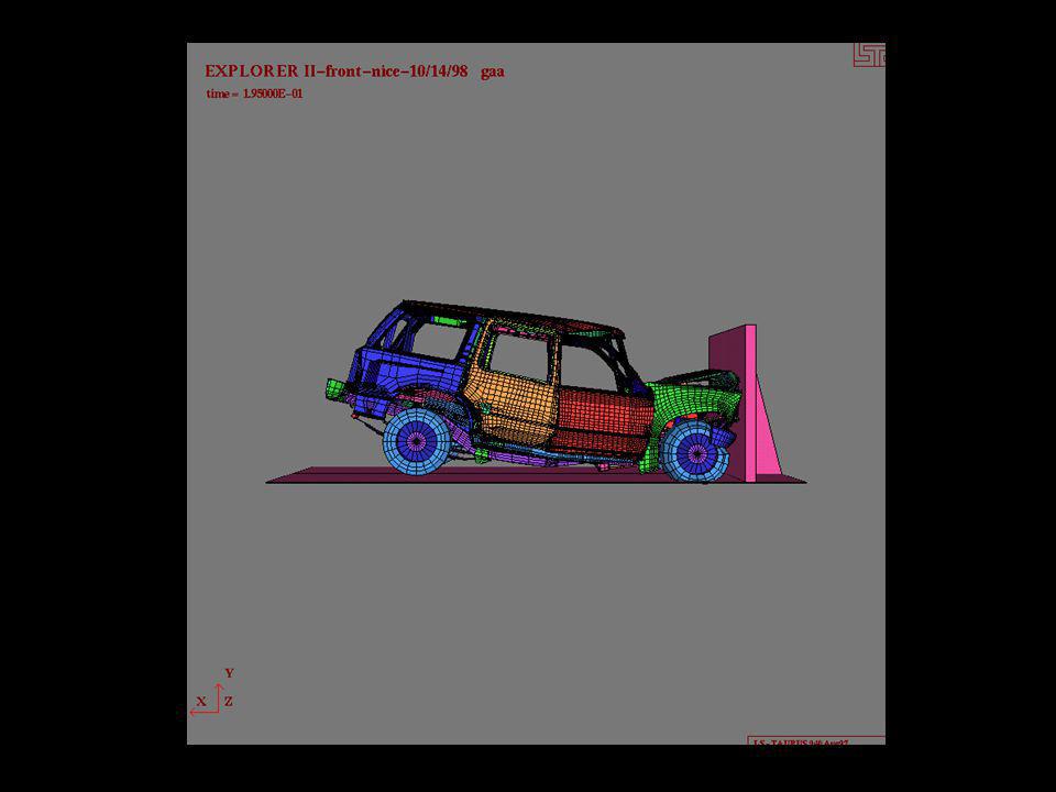
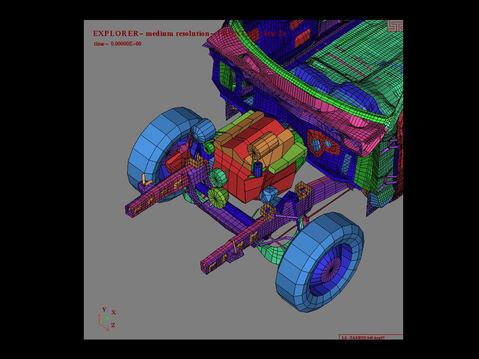
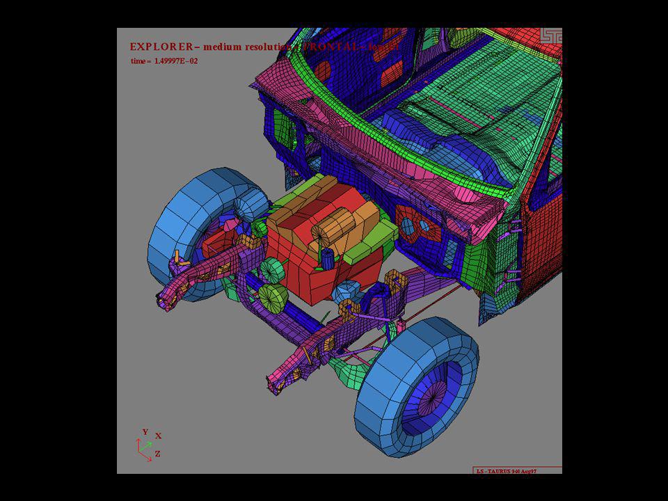
Frontal Impact Model

21
Rear Impact

22
Frontal Impact

23
FEM Mesh Parametrization Clean up geometry –connections between CAD surfaces must be accurate –CAD surfaces must be reorganized to fit FEM model Pick up general mesh topology For each part develop FEM mesh projection approach Determine topology constrains enforced by neighboring parts Create FEM mesh through projections on CAD surfaces

27
FEM Mesh Parametrization Enforce FEM mesh connectivity through part boundaries by mesh topology constraints Make FEM mesh projections using CAD entities, not coordinates Make things as you go –CAD, FEM mesh, mesh generator scripts, parsers, CAD-to-FEM-to-CAD, visualization Debug!

30
Basic FEM Model

31
Coarse FEM Mesh

32
Basic Model - Results

40
Frontal Impact Model

50
Frontal Impact - Results

64
Model Modifications Immediate fixes –Engine mounts damping effect –Elevate frame –Reconnect left body mount –Break-off conditions for bumper Users can specify needed modifications as they run simulations

65
Offset Impact Model

67
Offset Impact - Results

70
Pole Impact Results

77
Rear Impact

78
Detailed FEM Mesh in the Back

79
Rear Impact

80
Frontal Impact

81
Side Impact Model

82
Detailed FEM Mesh on the Side

83
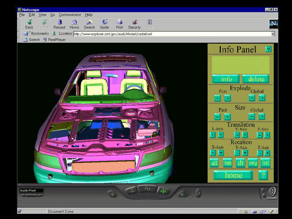
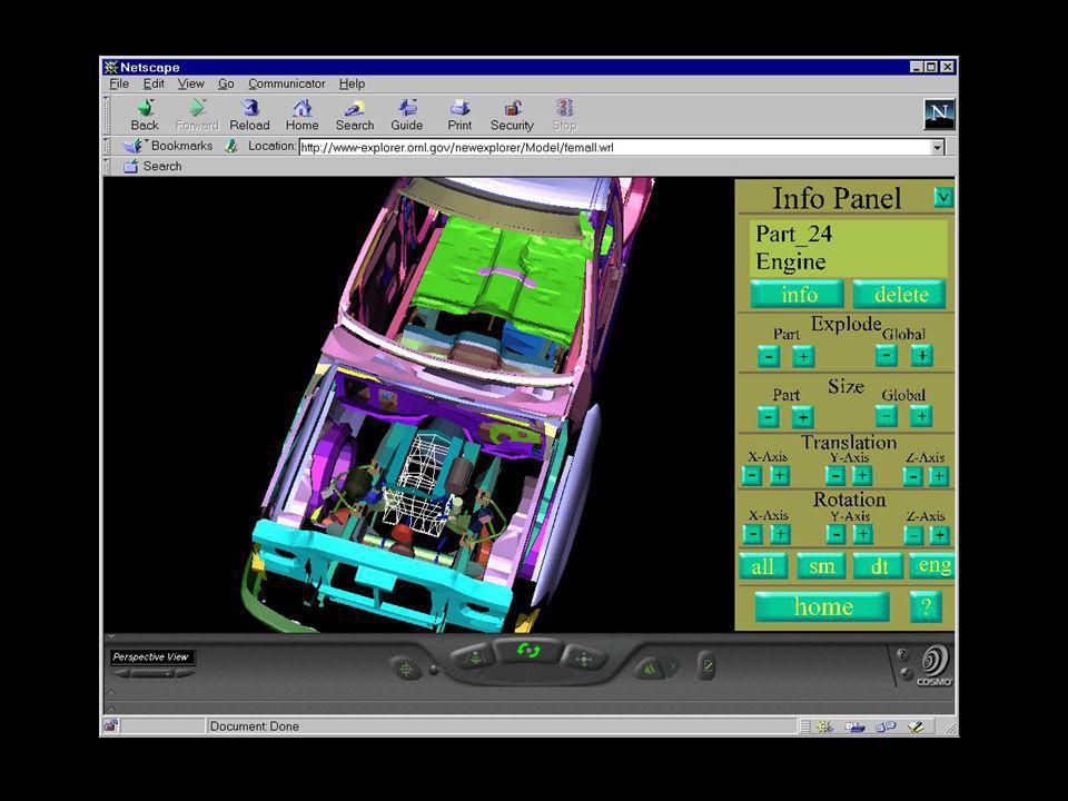
WWW Model Interface Large number of mesh control parameters in basic model (> 200) –very flexible FEM mesh topology –direct parameter manipulation intractable to anyone other than model developers Model modification can be facilitated through VRML interface User access through API-like process
 –very flexible FEM mesh topology –direct parameter manipulation intractable to anyone other than model developers Model modification can be facilitated through VRML interface User access through API-like process")
88
To Do - FEM Model Related Frame modifications –engine placement and mounts –transmission placement and mounts –drive axle placement –raise frame Body modifications –close few minor gaps

93
To Do - Parametric FEM Related Mesh topology –parameter placement evaluations (need suggestions) –parameter propagation tests Verify with NHTSA tests WWW interface for FEM model –parameter propagation display (needs speed fix) –connection between parts –subpart display –parameter display and user input (speed fix) –set up server for remote mesh generation (Unix, Win/NT) –develop annotation procedure (primitives developed)
 –parameter propagation tests Verify with NHTSA tests WWW interface for FEM model –parameter propagation display (needs speed fix) –connection between parts –subpart display –parameter display and user input (speed fix) –set up server for remote mesh generation (Unix, Win/NT) –develop annotation procedure (primitives developed)")
94
Deliverables Current LS DYNA3D models available on WWW –www-explorer.ornl.gov Next model release in early December 1998 –we can generate specific models in the meantime if needed, please help us to debug! –Full verification with NHTSA tests –materials property update as becomes available WWW interface for model inspection –new releases available daily

Similar presentations


 Fracture Behavior Computer Simulation (d) Lab Testing>")


 Use of computer systems to assist in the creation, modification, analysis, and optimization.>")


