Download presentation
Presentation is loading. Please wait.

1
CDROM, Floppy and Hard Disk Structure
Plus some basic concepts

2
Table of Contents CD Floppy Disk History Structure Data Recording
How The CD Drive Works CD File Systems Multiple Sessions CD-ReWritable (CD-RW) DVD Floppy Disk History Structure Data Recording/Retrieval Formatting 3½ Inch (2HD) Disks Hard Disk Some Basic Concepts Boot Sector Cluster FAT NTFS
 DVD. Floppy Disk. History. Structure. Data Recording/Retrieval. Formatting. 3½ Inch (2HD) Disks. Hard Disk. Some Basic Concepts. Boot Sector. Cluster. FAT. NTFS.")
3
PART 1 CD-ROM

5
History Compact Disc - Digital Audio (CD-DA), the original CD specification developed by Philips and Sony in 1980 Specifications were published in Red Book, continued to be updated (lastest version in 1999) In 1985 a standard for the storage of computer data by Sony and Philips, CD-ROM (Compact Disc Read Only Memory) Developments in the technology have been ongoing and rapid Compact disc Interactive (CD-I) Compact Disc Television (CD-TV) Compact Disc Recording (CD-R) Digital Video Disc (DVD)
 In 1985 a standard for the storage of computer data by Sony and Philips, CD-ROM (Compact Disc Read Only Memory) Developments in the technology have been ongoing and rapid. Compact disc Interactive (CD-I) Compact Disc Television (CD-TV) Compact Disc Recording (CD-R) Digital Video Disc (DVD)")
6
Structure The thickness of a CD can vary between 1.1 and 1.5mm
CDROM can store 720 MB of data. A CD consists of four layers The biggest part is clear polycarbonate (nominally 1.2mm) There is a very thin layer of reflective metal (usually aluminum) on top of the polycarbonate Then a thin layer of some protective material covering the reflective metal A label or some screened lettering on top of protective material
 There is a very thin layer of reflective metal (usually aluminum) on top of the polycarbonate. Then a thin layer of some protective material covering the reflective metal. A label or some screened lettering on top of protective material.")
7
CD Layers (cont’d)
")
8
Structure A CDROM Drive uses a small plastic-encapsulated disk that can store data This information is retrieved using a Laser Beam A CD can store vast amounts of information because it uses light to record data in a tightly packed form

9
Structure (cont’d) On surface of CDROM, laser beam to use to was be "punched" to according the spiral called the pits. These positions do not have "punch" as land. The 0.12 micron deep pit, approximately 0.6 microns wide. The pit and land length from 0.9 to 3.3 microns. The distance between the spiral is 1.6 micron. Track density on a CDROM is about 16,000 tracks per inch.

11
CD Safety The label side of a CD is the most vulnerable part of the disk The other side is protected by the thick (1.2mm) and hard polycarbonate It is possible to carefully clean and even to polish this surface to remove fingerprints and even scratches Many flaws on the polycarbonate surface will simply go unread.

12
CD vs. Magnetic Media In Magnetic Media (like floppy/hard disk) the surface is arranged into concentric circles called “tracks” Number of sectors per track is constant for all tracks The CD has one single track, starts at the center of the disk and spirals out to the circumference of the disk This track is divided into sectors of equal size

13
CD Data Recording Information is recorded on a CD using a series of bumps Laser gun Controller curcuit In the recording, Lazer gun was used to write data to disk Signal corresponding to 0 => laser off. Signal corresponding to 1 => laser on => burned disk surface into a point of losing the ability to reflect

14
Data Recording (cont’d)
The unmarked areas between pits are called "lands” Lands are flat surface areas The information is stored permanently as pits and lands on the CD-ROM. It cannot be changed once the CD-ROM is mastered, this is why its called CD-ROM

15
Data Reading Laser gun Lens Prism Sensitive diode Laser reflection on rotating disk surface, the pit will be lost reflected rays => that is “0” signal, the land they received reflected rays => that is “1” signal

16
How The CD Drive Works A motor rotates the CD
The rotational speed varies so as to maintain a constant linear velocity (the disk is rotated faster when its inner "SPIRALS" are being read)
")
17
How The CD Drive Works (cont’d)
A laser beam is shone onto the surface of the disk The light is scattered by the pits and reflected by the lands, these two variations encode the binary 0's and 1's A light sensitive diode picks up the reflected laser light and converts the light to digital data

18
How The CD Drive Works (cont’d)
")
19
Information transfer rate
CD-ROM Drive Speed The CD-ROM drives are classified by their rotational speed Based on the original speed of a CD-Audio (e.g. A "2X" CD-ROM drive will run at twice the speed of a CD- Audio) Speed Information transfer rate 1X 150 Kbytes/s 2X 300 Kbytes/s …
 Speed. Information transfer rate. 1X. 150 Kbytes/s. 2X. 300 Kbytes/s. …")
20
CD Physical Specifications
Diameter 120mm ±0.3mm Transparent Layer Thickness 1.2mm ±0.1mm Total Thickness 1.1mm - 1.5mm Transparent Layer Index of Refraction 1.55 ±0.10 Reflectance of Metal Layer through Transparent Layer 70% minimum Laser Wavelength 780nm ±10nm Track Pitch 1.6 micron ±0.1 micron Scanning Linear Velocity 1.20m/s m/s (±0.01m/s)
")
21
CD File Systems 1. ISO-9660 The base standard defines three levels of compliance Level 1 limits file names to 8+3 format. Many special characters (space, hyphen, equals, and plus) are forbidden Level 2 and 3 allow longer filenames (up to 31) and deeper directory structures (32 levels instead of 8) Level 2 and 3 are not usable on some systems, special MS-DOS
 are forbidden. Level 2 and 3 allow longer filenames (up to 31) and deeper directory structures (32 levels instead of 8) Level 2 and 3 are not usable on some systems, special MS-DOS.")
22
CD File Systems (cont’d)
2. Rock Ridge Extensions to ISO-9660 file system Favored in the Unix world Lifts file name restrictions, but also allows Unix-style permissions and special files to be stored on the CD Machines that don't support Rock Ridge can still read the files because it's still an ISO-9660 file system (they won't see the long forms of the names) UNIX systems and the Mac support Rock Ridge DOS and Windows currently don't support it
 UNIX systems and the Mac support Rock Ridge. DOS and Windows currently don t support it.")
23
CD File Systems (cont’d)
3. Joliet Favored in the MS Windows world Allows Unicode characters to be used for all text fields (including file names and the volume name) Disk is readable as ISO-9660, but shows the long filenames under MS Windows HFS (Hierarchical File System) Used by the Macintosh in place of the ISO-9660, making the disk unusable on systems that don't support HFS
 Disk is readable as ISO-9660, but shows the long filenames under MS Windows. HFS (Hierarchical File System) Used by the Macintosh in place of the ISO-9660, making the disk unusable on systems that don t support HFS.")
24
Multiple Sessions Allows CDs to be written more than once (not re-written) Some CD writers support this feature About 640MB of data can be written to the CD, as some space is reserved for timing and other information Each session written has an overhead of approximately 20MB per session

25
CD-ReWritable (CD-RW)
It is essentially CD-R Allows discs to be written and re-written up to 1000 times The storage capacity is the same as that for CD-R Based on phase-change technology. The recording layer is a mixture of silver, indium, antimony and tellurium

26
CD-RW Recording Process
The recording layer is polycrystalline The laser heats selected areas of the recording track to the recording layer's melting point of 500 to 700 degrees Celsius

27
CD-RW Recording (cont’d)
The laser beam melts the crystals and makes them non-crystalline (amorphous phase) The medium quickly cools, locking in the properties of the heated areas The amorphous areas have a lower reflectivity than the crystalline areas This creates a pattern which can be read as pits and lands of the traditional CD To erase a CD-RW disc, the recording laser turns the amorphous areas back into crystalline areas
 The medium quickly cools, locking in the properties of the heated areas. The amorphous areas have a lower reflectivity than the crystalline areas. This creates a pattern which can be read as pits and lands of the traditional CD. To erase a CD-RW disc, the recording laser turns the amorphous areas back into crystalline areas.")
28
DVD Digital Versatile Disk (Formerly Digital Video Disk)
Same size (120mm) and thickness (1.2mm) as CD Improvements in the logarithms used for error correction Much greater data accuracy using smaller Error Correction Codes (ECC) More effective use of the track space
 and thickness (1.2mm) as CD. Improvements in the logarithms used for error correction. Much greater data accuracy using smaller Error Correction Codes (ECC) More effective use of the track space.")
29
DVD vs. CD DVD uses a tighter spiral (track or helix) with only 0.74 microns between the tracks (1.6 microns on CDs) DVD recorders use a laser with a smaller wavelength, 635nm or 650 nm (visible red light) vs. 780nm (infrared) for CDs DVD has smaller "burns" (pits) in the translucent dye layer (0.4 microns minimum vs microns minimum on CDs) These technologies allow DVDs to store large amounts of data
 vs. 780nm (infrared) for CDs. DVD has smaller burns (pits) in the translucent dye layer (0.4 microns minimum vs microns minimum on CDs) These technologies allow DVDs to store large amounts of data.")
30
DVD (cont’d) Standard single-sided DVDs store up to 4.7GB of data
Dual-sided discs hold about 8.5GB of data (9.4GB for back-to-back layers dual-sided discs) In back-to-back layers discs, it must be turned over to access the data on the reverse side DVD uses MPEG2 compression for high quality pictures DVD drives have a much faster transfer rate than CD drives DVD-ROM drives will read and play existing CD-ROM and CD-A disks
 In back-to-back layers discs, it must be turned over to access the data on the reverse side. DVD uses MPEG2 compression for high quality pictures. DVD drives have a much faster transfer rate than CD drives. DVD-ROM drives will read and play existing CD-ROM and CD-A disks.")
31
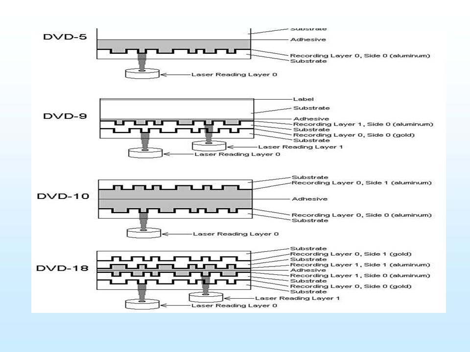
DVD (cont’d) Types Characteristics DVD-5
4.7GB Single-Side, Single-Layer capacity 4,7 GB. DVD-9 8.5GB Single-Side, Dual-Layer Capacity 8,5 GB. DVD-10 9.4GB Double-Side, Single-Layer Capacity 9,4 GB. DVD-18 17.1GB Double-Side, Dual-Layer Capacity 17,1 GB.

33
PART 2 Blu-ray VS HD-DVD

34
Blu-ray disc Blu-ray Disc (official abbreviation BD) is an optical disc storage medium designed to replace the DVD format. The standard physical medium is a 12 cm plastic optical disc, the same size as DVDs and CDs. Blu-Ray Discs contain 25 GB per layer, with dual layer discs (50 GB) the norm for feature-length video discs and additional layers possible later.
 the norm for feature-length video discs and additional layers possible later.")
35
HD - DVD HD DVD-ROM, HD DVD-R and HD DVD-RW have a single-layer capacity of 15 GB, and a dual-layer capacity of 30 GB. HD DVD-RAM has a single-layer capacity of 20 GB. Like the original DVD format, the data layer of an HD DVD is 0.6 mm below the surface to physically protect the data layer from damage. All HD DVD players are backward compatible with DVD and CD.

36
USB Flash drive A USB flash drive consists of a flash memory data storage device integrated with a USB (Universal Serial Bus) interface. USB flash drives are typically removable and rewritable, and physically much smaller than a floppy disk. Most weigh less than 30 gram. Storage capacities in 2010 can be as large as 256 GB with steady improvements in size and price per capacity expected.

37
USB speed USB 1.0 – speed 1.5 Mb/s USB 1.1 – speed 12 Mb/s
USB 3.0 – speed 5 Gb/s

38
Hard disk drive Disk platter Read/Write head Head arm/Head slider
Head actuator mechanism Spindle motor Logic board Air filter Cables & Connectors

39
Hard Disk Fixed and removable
Fast (disk rotates at 60 to 200 times per second) Currently 20 – 2 TB (may be limited by the version of the operating system) Like floppies, uses the magnetic properties of the coating material, but the technology is different
 Currently 20 – 2 TB (may be limited by the version of the operating system) Like floppies, uses the magnetic properties of the coating material, but the technology is different.")
40
Boot Sector (Boot Record)
A vital sector, disk will be unusable if this sector damages MBR at CHS 0, 0, 1 in hard disks, contains Partition Table Each partition has its own boot sector too Each operating system has its own boot sector format For Booting, Bootstrap Loader loads Boot Sector data it in a particular address of memory (0000:7C00h) and sets the PC In hard disks, the small program in MBR attempts to locate an active (bootable) partition in partition table If found, the boot record of that partition is read into memory (location 0000:7C00) and runs
 and sets the PC. In hard disks, the small program in MBR attempts to locate an active (bootable) partition in partition table. If found, the boot record of that partition is read into memory (location 0000:7C00) and runs.")
41
DOS/Win Formatted Disk
A DOS/Win formatted floppy/hard disk’s Boot Sector contains A jump and a NOP (No Operation Performed) op-code (operation code) BPB (BIOS Parameter Block) Sectors per cluster Number of Root directory entries Sectors per FAT Volume Label … A program, to load OS if bootable/show error msg if not in floppies, to locate the active partition in hard disks Error messages
 op-code (operation code) BPB (BIOS Parameter Block) Sectors per cluster. Number of Root directory entries. Sectors per FAT. Volume Label. … A program, to load OS if bootable/show error msg if not in floppies, to locate the active partition in hard disks. Error messages.")
42
Cluster Data units of disk must be addressed, which units belong to which file / are free / are damaged (bad sectors) / … On disks having large capacity, purposing one sector as a unit makes addressing table so large Cluster is defined Represents the smallest amount of disk space that OS can be allocated The smaller the cluster size, the more efficiently disk space usage, the more number of bits to address one unit The number of sectors per cluster is stored in the Boot Record

43
FAT FAT-12/FAT-16/FAT-32 are Microsoft favorite File Allocation Tables (before NTFS) FAT-12 uses 12 bits for addressing, a max. of 4096 units, considering one sector as a cluster, 2MB can be addressed FAT-16 with max.(128) sectors/cluster (64KB cluster size wasting large amount of disk space) up to 4GB, this is why Win95 cannot support more than 4GB partiotions FAT-32, the same system, 32 bit fields for addressing
 sectors/cluster (64KB cluster size wasting large amount of disk space) up to 4GB, this is why Win95 cannot support more than 4GB partiotions. FAT-32, the same system, 32 bit fields for addressing.")
44
NTFS NT File System Better performance Less wasted space More security
Supports all sizes of clusters (512b - 64 KB) The 4 KB cluster is somehow standard Practically no partition size limitation Very flexible, all the system files can be relocated, except the first 16 MFT (Master File Table) elements
 The 4 KB cluster is somehow standard. Practically no partition size limitation. Very flexible, all the system files can be relocated, except the first 16 MFT (Master File Table) elements.")
45
NTFS (cont’d) NTFS disk is symbolically divided into two parts
The first 12% is assigned to MFT area The rest 88% represents usual space for files storage MFT area can simply reduce if needed, clearing the space for recording files At clearing the usual area, MFT can be extended again

46
Hard Drive Interfaces ATA interfaces dominate today’s market
Many changes throughout years Parallel ATA (PATA) historically prominent Serial ATA (SATA) since 2003 Small Computer System Interface (SCSI) Pronounced “Scuzzy” Used in many high-end systems
 historically prominent. Serial ATA (SATA) since Small Computer System Interface (SCSI) Pronounced Scuzzy Used in many high-end systems.")
47
ATA Overview IDE - International Development Enterprises Cable
Keywords Speed Max size ATA-1 40-pin PIO and DMA 3.3 MBps to 8.3 MBps 504 MB ATA-2 EIDE ATAPI 11.1 MBps to 16.6 MBps 8.4 GB ATA-3 SMART ATA-4 Ultra 16.7 MBps to 33.3 MBps INT13 BIOS Upgrade 137 GB ATA-5 40-pin 80-wires ATA/33 ATA/66 44.4 MBps to 6.6 MBps ATA-6 Big Drive 100 MBps 144 PB ATA-7 80-wires 7-pin ATA/133 SATA 133 MBps to 300 MBps IDE - International Development Enterprises

48
ATA-1 Programmable I/O (PIO)—traditional data transfer
3.3 MBps to 8.3 MBps DMA—direct memory access 2.1 MBps to 8.3 MBps Allowed two drives (one master, one slave)
")
49
ATA-2 Commonly called EIDE (though a misnomer)
Added second controller to allow for four drives instead of only two Increased size to 8.2 GB Added ATAPI Could now use CD drives

50
ATA-3 Self-Monitoring Analysis and Reporting Technology
S.M.A.R.T. No real change in other stats

51
ATA-4 Introduced Ultra DMA Modes Ultra DMA Mode 2 also called ATA/33
Ultra DMA Mode 0: 16.7 MBps Ultra DMA Mode 1: 25 MBps Ultra DMA Mode 2: 33 MBps Ultra DMA Mode 2 also called ATA/33

52
INT13-Interrupt Extensions
ATA-1 standard actually written for hard drives up to 137 GB BIOS limited it to 504 MB due to cylinder, head, and sector maximums ATA-2 implemented LBA (Logical block addressing) to fool the BIOS, allowing drives to be as big as 8.4 GB INT13 Extensions extended BIOS commands Allowed drives as large as 137 GB
 to fool the BIOS, allowing drives to be as big as 8.4 GB. INT13 Extensions extended BIOS commands. Allowed drives as large as 137 GB.")
53
ATA-5 Introduced newer Ultra DMA Modes Ultra DMA Mode 3: 44.4 MBps
Ultra DMA Mode 4 also called ATA/66 Used 40-pin cable, but had 80 wires Blue connector—to controller Gray connector—slave drive Black connector—master drive ATA/66 cable

54
ATA-6 “Big Drives” introduced
Replaced INT13 & 24-bit LBA to 48-bit LBA Increased maximum size to 144 PB 144,000,000 GB Introduced Ultra DMA 5 Ultra DMA Mode 5: 100 MBps ATA/100 Used same 40-pin, 80-wire cables as ATA-5

55
ATA-7 Introduced Ultra DMA 6 Ultra DMA Mode 6: 133 MBps ATA/133
Used same 40-pin, 80-wire cables as ATA-5 Didn’t really take off due to SATA’s popularity Introduced Serial ATA (SATA) Increased throughput to 150 MBps to 300 MBps
 Increased throughput to 150 MBps to 300 MBps.")
56
Serial ATA Hot-swappable Can have as many as eight SATA devices
Serial ATA (SATA) creates a point-to-point connection between the device and the controller Hot-swappable Can have as many as eight SATA devices Thinner cables resulting in better airflow and cable control in the PC Maximum cable length of inches compared to 18 inches for PATA cables
 creates a point-to-point connection between the device and the controller. Hot-swappable. Can have as many as eight SATA devices. Thinner cables resulting in better airflow and cable control in the PC. Maximum cable length of 39.4 inches compared to 18 inches for PATA cables.")
57
Serial ATA More on SATA eSATA
PATA device my be connected to SATA using a SATA bridge Can have as many as eight SATA devices Add more SATA functionality via a PCI card eSATA External SATA Extends SATA bus to external devices eSATA Port

58
SCSI Small Computer System Interface

59
SCSI Pronounced “Scuzzy” Been around since ’70s
Devices can be internal or external Historically the choice for RAID Faster than PATA Could have more than four drives SATA replacing SCSI in many applications

60
SCSI Chains A SCSI chain is a series of SCSI devices working together through a host adapter The host adapter is a device that attaches the SCSI chain to the PC All SCSI devices are divided into internal and external groups The maximum number of devices, including the host adapter, is 16

61
Internal Devices Internal SCSI devices are installed inside the PC and connect to the host adapter through the internal connector Internal devices use a 68-pin ribbon cable Cables can be connected to multiple devices

62
External Devices External SCSI devices are connected to host adapter to external connection of host adapter External devices have two connections in the back, to allow for daisy-chaining A standard SCSI chain can connect 15 devices, including the host adapter

63
SCSI IDs Each SCSI device must have a unique SCSI ID
The values of ID numbers range from 0 to 15 No two devices connected to a single host adapter can share the same ID number No order for the use of SCSI IDs, and any SCSI device can have any SCSI ID Make sure you can look at any SCSI device and understand how to set its SCSI ID!

64
SCSI IDs The SCSI ID for a particular device can be set by configuring jumpers, switches, or even dials Use your hexadecimal knowledge to set the device ID Device 1 = Off, Off, Off, On Device 7 = Off, On, On, On Device 15 = On, On, On, On Host adapters often set to 7 or 15 but can be changed

65
Termination Terminators are used to prevent a signal reflection that can corrupt the signal Pull-down resistors are usually used as terminators Only the ends of the SCSI chains need to be terminated Most manufacturers build SCSI devices that self-terminate Discussion Point Termination All electronic signals can reflect back (or echo) along the wire. On some systems, such as SCSI and coaxial networks, this can cause chaos, as devices do not know what signal to listen to. A terminator is basically a resistor that absorbs the signal to prevent it from reflecting back. All SCSI chains, without exception, have to be terminated at both ends of the chain, but never in the middle.
 along the wire. On some systems, such as SCSI and coaxial networks, this can cause chaos, as devices do not know what signal to listen to. A terminator is basically a resistor that absorbs the signal to prevent it from reflecting back. All SCSI chains, without exception, have to be terminated at both ends of the chain, but never in the middle.")
66
Protecting Data with RAID

67
Protecting Data The most important part of a PC is the data it holds
Companies have gone out of business because of losing data on hard drives Hard drives will eventually develop faults Fault tolerance allows systems to operate even when a component fails Redundant Array of Inexpensive Disks (RAID) is one such technology
 is one such technology.")
68
RAID Level 0 Disk striping Not fault tolerant
Writes data across multiple drives at once Requires at least two hard drives Provides increased read and writes Not fault tolerant If any drive fails, the data is lost

69
RAID Level 1 Disk mirroring/duplexing is the process of writing the same data to two drives at the same time Requires two drives Produces an exact mirror of the primary drive Mirroring uses the same controller Duplexing uses separate controllers

70
RAID Levels 2 to 4 RAID 2 RAID 3 and 4
Disk striping with multiple parity drives Not used RAID 3 and 4 Disk striping with dedicated parity Dedicated data drives and dedicated parity drives Quickly replaced by RAID 5

71
RAID Level 5 Disk striping with distributed parity
Distributes data and parity evenly across the drives Requires at least three drives Most common RAID implementation Software-based RAID 5

72
RAID 5 (Stripe with Parity)
Decimal 22 21 20 4 2 1 3 Decimal 21 20 Odd Parity 2 1 3 1 Data 1 Data 1 Parity

73
RAID Level 6 Super disk striping with distributed parity
RAID 5 with asynchronous and cached data capability The CompTIA A+ Certification exams are interested only in your understanding RAID levels 0, 1, and 5. I’m unaware of anyone actually using RAID levels 2, 3, or 4 in modern systems. Just be aware that these other levels of RAID exist.

74
Implementing RAID SCSI has been the primary choice in the past
Faster than PATA PATA allowed only four drives SATA today viewed as comparable choice Speeds comparable to SCSI Dedicated SATA controllers can support up to 15 drives

75
Hardware vs. Software Hardware RAID Software RAID Dedicated controller
Operating system views it as single volume Software RAID Operating system recognizes all individual disks Combines them together as single volume

76
Personal RAID ATA RAID controller chips have gone down in price
Some motherboards are now shipping with RAID built-in The future is RAID RAID has been around for 20 years but is now less expensive and moving into desktop systems

77
THANK YOU

Similar presentations


>")


