Download presentation
Presentation is loading. Please wait.

1
Instructor SGT Christopher Vester Bco 62nd Engineers
Prepare a Range Card Instructor SGT Christopher Vester Bco 62nd Engineers

2
Task: Prepare a Range Card
Conditions: During daylight in a defensive fighting position, given your assigned weapon system. You have an assigned sector of fire and secondary sector of fire (both with recognizable targets). You have blank standard range cards (DA FM 5517-R), a pencil, a lensatic compass, and a map of the area. Standards: Prepare a range card for your assigned position in duplicate. Sketch in the terrain in you assigned sector of fire. Sketch in sector limits, the gun symbol, and dead space. Complete the DATA section by entering the weapon, the unit, the data, and sketch in magnetic north direction. Sketch in terrain features that are likely targets, numbering them in priority. Record the direction, elevation, range and description of each target
. You have blank standard range cards (DA FM 5517-R), a pencil, a lensatic compass, and a map of the area. Standards: Prepare a range card for your assigned position in duplicate. Sketch in the terrain in you assigned sector of fire. Sketch in sector limits, the gun symbol, and dead space. Complete the DATA section by entering the weapon, the unit, the data, and sketch in magnetic north direction. Sketch in terrain features that are likely targets, numbering them in priority. Record the direction, elevation, range and description of each target.")
3
The success of a defense depends on the positioning of soldiers and weapons. To position their weapons effectively, platoon leaders must know the characteristics, capabilities, and limitations of their weapons, the effects of terrain, and the enemy. However, the platoon leader is not done after merely positioning his weapons. He must ensure that each weapon can effectively engage the enemy, and the sum of his weapons can effectively mass coordinated direct fires on the enemy. The platoon leader accomplishes this by making his soldiers produce detailed range cards and by making his squad leaders and section leaders produce detailed, coordinated sector sketches. He personally inspects individual soldier positions, reviews subordinate sector sketches, and coordinates with adjacent units to develop a detailed and accurate platoon sector sketch.

4
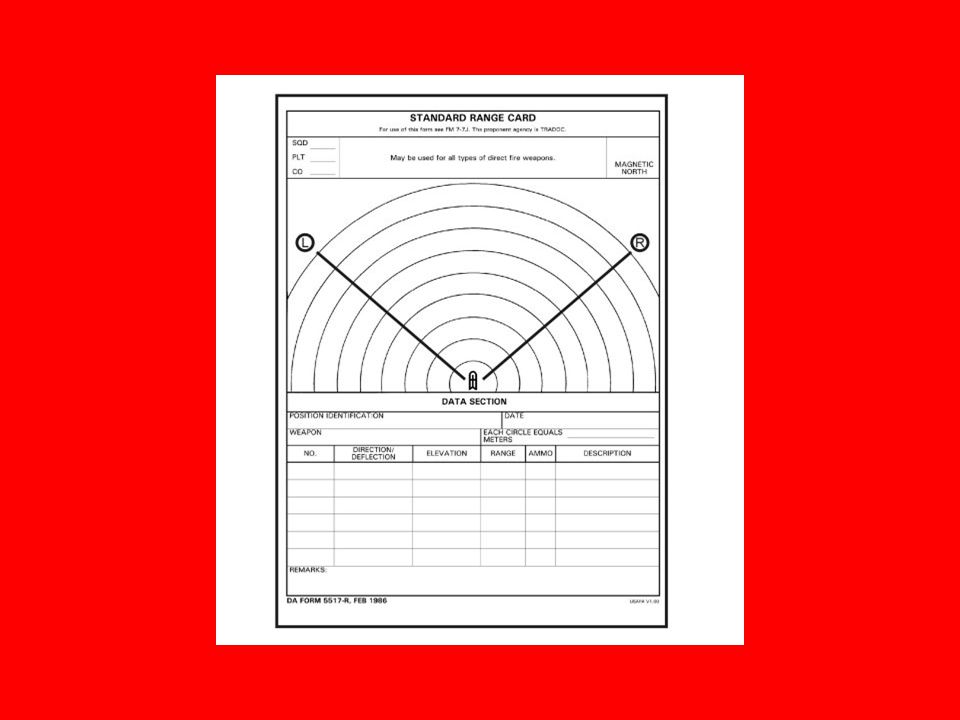
Range Card A range card is a sketch of the assigned sector that a direct fire weapon system is intended to cover. A range card aids in planning and controlling fires and aids the crews and squad gunners in acquiring targets during limited visibility. It is also an aid for replacement personnel or platoons or squads to move into the position and orient on their sector. The individual soldier or gunner should make the range card so that he becomes more familiar with the terrain in his sector. He should continually assess the sector and, if necessary, update his range card. To prepare a range card, the gunner must know the following information.

5
Sectors of fire. Target reference points. Dead space. Maximum engagement line. Weapons or gunners reference point. Weapons symbol, left and right limits, and north seeking arrow.

6
Sectors of Fire A sector of fire is a piece of the battlefield for which a gunner is responsible. He may be assigned a primary and a secondary sector. Leaders use sectors of fire to ensure fires are distributed across the platoon’s area of responsibility. A sector of fire is assigned to cover possible enemy avenues of approach. Leaders should overlap sectors to provide the best use of overlapping fire and to cover areas that cannot be engaged by a single weapon system. The leader assigns left and right sector limits using prominent terrain features or easily recognizable objects such as large rocks, telephone poles, fences, or stakes.

8
Reference Points and Target Reference Points
Leaders designate natural or man-made features as reference points. A soldier uses these reference points for target acquisition and range determination. Some reference points may also be designated as target reference points. A TRP is an easily recognizable point on the ground (natural or manmade) used to initiate, distribute, and control fires. The company or battalion designates TRPs, and platoon and squad leaders also should designate TRPs. TRPs always should be visible. These also may be useful as indirect-fire targets. The commander or platoon leader designates TRPs used as indirect fire targets so that target numbers can be assigned. TRPs should be visible through all spectrums available to the unit. They must be easily identifiable to the defender during daylight. TRPs must be heated so they can be recognized with thermal sights, and they must have an infrared signature so they can be recognized through night vision devices.
 used to initiate, distribute, and control fires. The company or battalion designates TRPs, and platoon and squad leaders also should designate TRPs. TRPs always should be visible. These also may be useful as indirect-fire targets. The commander or platoon leader designates TRPs used as indirect fire targets so that target numbers can be assigned. TRPs should be visible through all spectrums available to the unit. They must be easily identifiable to the defender during daylight. TRPs must be heated so they can be recognized with thermal sights, and they must have an infrared signature so they can be recognized through night vision devices.")
10
Dead Space Dead space is any area that cannot be observed or covered by direct-fire systems within the sector of fire. All dead space within the sector must be identified to allow the platoon leaders and squad leaders to plan indirect fires (mortars, artillery, MK19, or M203) to cover the area. The squad leader must walk the engagement area to identify dead space for his M249s and M240B. When the vehicles are used in the defense, the section leaders must walk the engagement area so gunners can detect dead spaces through their remote weapons sighting system.
 to cover the area. The squad leader must walk the engagement area to identify dead space for his M249s and M240B. When the vehicles are used in the defense, the section leaders must walk the engagement area so gunners can detect dead spaces through their remote weapons sighting system.")
12
Maximum Engagement Line
The MEL is the depth of the sector and normally is limited to the maximum effective engagement range of the weapons systems. However, it can be less if there are objects that prevent the soldier from engaging targets at maximum effective ranges of his assigned weapon. To assist in determining the distance to each MEL, the soldier should use a map to ensure that the MELs are depicted accurately on the range card. Identifying the MEL will decrease ammunition expenditure during an engagement.

14
Weapons symbol, left and right limits, and north seeking arrow.
Weapon Symbol. Indicates the type of weapon that the range card was designed for. Magnetic North. Take the range card and orient it with the assigned sector of fire. Use a lensatic compass to determine magnetic north. Keep the range card oriented to the sector of fire and draw the magnetic north symbol in the appropriate direction in the Magnetic North box. Left Limit and Right Limit. Left and right limits are imaginary lines from the gunner’s firing position to a designated point on the ground. Use terrain features when possible to designate left and right limits. Other recognizable objects such as a building or other man-made structures can be used. The area between the left and right limits depicts the gunner’s sector of fire or area of responsibility.

16
Armored Vehicle Symbols
Weapon Symbols Armored Vehicle Symbols

18
Preparation Procedures
The individual soldier or gunner prepares two copies of the range card. If alternate and supplementary firing positions are assigned, two copies are required for these as well. One copy is kept with the gunner and the other is given to the section or squad leader for his sketch.

19
Placement of weapon symbol and left and right limits.
Draw the weapon symbol in the center of the small circle. Draw two lines from the position of the weapons system extending left and right to show the limits of the sector. The area between the left and right limits depicts the gunner’s sector of fire or area of responsibility. Number the left limit as No. 1, number the right limit No. 2, and place a circle around each number. Record the azimuth and distance of each limit in the data section.

20
Circle Value Determine the value of each circle by finding a terrain feature farthest from the position and within the weapon system’s capability. Determine the distance to the terrain feature. Round off the distance to the next even hundredth, if necessary. Determine the maximum number of circles that will divide evenly into the distance. The result is the value of each circle. Draw the terrain feature on the appropriate circle on the range card. Clearly mark the increment for each circle across the area where DATA SECTION is written. For example, in the picture a hilltop at 3,145 meters is used. The distance is rounded to 3,200 meters, divided by 8, and equals 400. Thus, each circle has a value of 400 meters.

21
Terrain Features for Left and Right Limits
The Picture, shows a farmhouse at 1,500 meters on the left limit. The wood line at 2,000 meters annotates the right limit. Determine the distance to these features by using a map or laser range finder. Note how the circle markings can assist in positioning the features on the range card.

22
Reference points and target reference points.
Draw all reference points and target reference points in the sector. Mark each with a circled number beginning with 1. The picture shows the hilltop as reference point (RP) 1, a road junction as RP 2, and road junction RP 3. There are times when a TRP and a reference point are the same point (for example, RP 2 and RP 3 above). The TRP is marked with the first designated number in the upper right quadrant, and the reference point is marked in the lower left quadrant of the cross. This occurs when a TRP is used for target acquisition and range determination. Road junctions are drawn by determining the range to the junction, by drawing the junction, and by drawing the connecting roads from the road junction.
 1, a road junction as RP 2, and road junction RP 3. There are times when a TRP and a reference point are the same point (for example, RP 2 and RP 3 above). The TRP is marked with the first designated number in the upper right quadrant, and the reference point is marked in the lower left quadrant of the cross. This occurs when a TRP is used for target acquisition and range determination. Road junctions are drawn by determining the range to the junction, by drawing the junction, and by drawing the connecting roads from the road junction.")
23
Dead Space Dead space is shown as an irregular circle with diagonal lines drawn inside. Any object that prohibits observation or coverage with direct fire will have the circle and diagonal lines extend out to the farthest maximum engagement line. If the area beyond the dead space can be engaged, the circle is closed.

24
Maximum engagement lines
MELs are shown as in the picture. They are drawn at the maximum effective engagement range per weapon if there is no dead space to limit their range capabilities. MELs are not drawn through dead space.

25
Weapon reference point
The WRP is represented as a line with a series of arrows extending from a known terrain feature and pointing in the direction of the weapon system symbol. This feature is numbered last. The WRP location is given a six-digit grid. When there is no terrain feature to be designated as the WRP, the weapon system’s location is shown as an eight-digit grid coordinate in the remarks block of the range card. (In the picture to the left the WRP is number 4.)
")
26
Example of a completed range card
Complete the data section. (1) Position Identification. List primary, alternate, or supplementary positions. Alternate and supplemental positions must be clearly identified. (2) Date. Show date and time the range card was completed. Range cards, like fighting positions, are constantly updated. The date and time are vital in determining current data. (3) Weapon. The weapon block indicates weapon type. (4) Each Circle Equals ____ Meters. Write in the distance, in meters, between circles. (5) NO (number). Start with L and R limits, then list TRPs and RPs in numerical order. (6) Direction/Deflection. The direction is listed in degrees. The deflection is listed in mils. (7) Elevation. The elevation is listed in mils. (8) Range. This is the distance, in meters, from weapon system position to L and R limits and TRPs and RPs. (9) Ammunition. List types of ammunition used. (10) Description. List the name of the object (for example, farmhouse, wood line, or hilltop). (11) Remarks. Enter the WRP data. As a minimum, WRP data includes a description of what the WRP is, its six-digit or eight digit grid coordinate, the magnetic azimuth, and the distance from the WRP to the position. d. Complete the marginal information at the top of the card. (1) Unit Description. Enter unit description such as squad, platoon, or company. Never indicate a unit higher than company. (2) Magnetic North. Orient the range card with the terrain and draw the direction of the magnetic north arrow.
 Position Identification. List primary, alternate, or supplementary positions. Alternate and supplemental positions must be clearly identified. (2) Date. Show date and time the range card was completed. Range cards, like fighting positions, are constantly updated. The date and time are vital in determining current data. (3) Weapon. The weapon block indicates weapon type. (4) Each Circle Equals ____ Meters. Write in the distance, in meters, between circles. (5) NO (number). Start with L and R limits, then list TRPs and RPs in numerical order. (6) Direction/Deflection. The direction is listed in degrees. The deflection is listed in mils. (7) Elevation. The elevation is listed in mils. (8) Range. This is the distance, in meters, from weapon system position to L and R limits and TRPs and RPs. (9) Ammunition. List types of ammunition used. (10) Description. List the name of the object (for example, farmhouse, wood line, or hilltop). (11) Remarks. Enter the WRP data. As a minimum, WRP data includes a description of what the WRP is, its six-digit or eight digit grid coordinate, the magnetic azimuth, and the distance from the WRP to the position. d. Complete the marginal information at the top of the card. (1) Unit Description. Enter unit description such as squad, platoon, or company. Never indicate a unit higher than company. (2) Magnetic North. Orient the range card with the terrain and draw the direction of the magnetic north arrow.")
27
Sector Sketches Individual soldiers, crew-served weapon crews in the squads, and ICV gunners prepare range cards. Squad leaders prepare squad sector sketches, and section leaders prepare section sector sketches. The platoon leader reviews his squads’ and sections’ sector sketches and ensures the sketches meet his intent. If he finds any gaps or other flaws, the platoon leader adjusts weapons locations or sectors. Once the platoon leader approves the squad and section sector sketches, he prepares a consolidated report for the company commander and incorporates this into a consolidated platoon sector sketch. The platoon leader or platoon sergeant physically prepares the platoon sector sketch. The sector sketch can be on acetate taped to a map or it can be a hand drawn sketch. Accurate and detailed sketches aid in direct fire planning and in direct fire control and distribution.

28
Squad and Section Sector Sketch
The squad leaders and section leaders make two copies of their sector sketches; one copy goes to the platoon leader, the other remains at the position. The squad leaders and section leaders draw sector sketches as close to scale as possible, showing: Main terrain features in the sector and the range to each. Each primary position. Engagement area or primary and secondary sectors of fire covering each position. M240B machine gun FPL or PDF (if applicable) M249 squad automatic weapon FPLs or PDFs. M2 and MK 19 FPLs or PDFs. Type of weapon in each position. Reference points and TRPs in the sector. Observation post locations. Dead space. Obstacles. MELs for all weapon systems. MELS for Javelin (if applicable) and AT4s. Indirect fire targets.
 M249 squad automatic weapon FPLs or PDFs. M2 and MK 19 FPLs or PDFs. Type of weapon in each position. Reference points and TRPs in the sector. Observation post locations. Dead space. Obstacles. MELs for all weapon systems. MELS for Javelin (if applicable) and AT4s. Indirect fire targets.")
29
Squad Sector Sketch

30
Questions?

Similar presentations


>")


