Download presentation
Presentation is loading. Please wait.

1
NATURAL AND STEP RESPONSES OF RLC CIRCUITS
NATURAL AND STEP RESPONSES OF RLC CIRCUITS

2
NATURAL RESPONSE OF A PARALLEL RALC CIRCUIT
iL I0 iR + + ic L R V0 V C Ordinary, second-order differential equation with constant coefficients. Therefore, this circuit is called a second-order circuit.

3
GENERAL SOLUTION OF SECOND-ORDER DIFFERENTIAL EQUATIONS
Assume that the solution of the differential equation is of exponential form V=Aest where A and s are unknown constants. This equation can be satisfied for all values of t only if A=0 or the term in parentheses is zero. A=0 cannot be used as a general solution because to do so implies that the voltage is zero for all time-a physical impossibility if energy is stored in either inductor or capacitor.

4
THE CHARACTERISTIC EQUATION
is called the characteristic equation The two roots of the characteristic equation are

5
If either s1 or s2 is substituted into Aest, the assumed solution satisfies the differential equation, regardless of the value of A These two solutions as well as their summation V=V1+V2 satisfy the differential equation

6
FREQUENCIES The behavior of V(t) depends on the values of s1 and s2. Writing the roots in a notation as widely used in the literature The exponent of e must be dimensionless, so both s1 and s2 (and hence and 0) must have the dimension of the reciprocal of time (frequency). s1 and s2 are referred to as complex frequencies, is called the neper frequency, and 0 is called the resonant radian frequency. They have the unit radians per second (rad/s)
 must have the dimension of the reciprocal of time (frequency). s1 and s2 are referred to as complex frequencies, is called the neper frequency, and 0 is called the resonant radian frequency. They have the unit radians per second (rad/s)")
7
The nature of the roots s1 and s2 depends on the values of and 0
The nature of the roots s1 and s2 depends on the values of and 0. There are three possible cases: 1) If 02<2, both roots will be real and distinct. The voltage response is said to be overdamped. 2) If 02>2, both roots will be complex and, in addition, will be conjugates of each other. The voltage response is said to be underdamped. 3) If 02=2, roots will be real and equal. The voltage response is said to be critically damped.
 If 02<2, both roots will be real and distinct. The voltage response is said to be overdamped. 2) If 02>2, both roots will be complex and, in addition, will be conjugates of each other. The voltage response is said to be underdamped. 3) If 02=2, roots will be real and equal. The voltage response is said to be critically damped.")
8
EXAMPLE I0 + + Find the roots of the characteristic equation if R=200 , L=50 mH, and C=0.2 F. C L R V0 V Overdamped

9
Repeat the problem for R=312.5
Underdamped

10
Find the value of R for a critically damped circuit.
For critical damping, 2=02

11
THE OVERDAMPED RESPONSE
When the roots of the characteristic equation are real and distinct, the response is said to be overdamped in the form The constant A1 and A2 are to be determined by the initial conditions V(0+) and dV(0+)/dt.
 and dV(0+)/dt.")
12
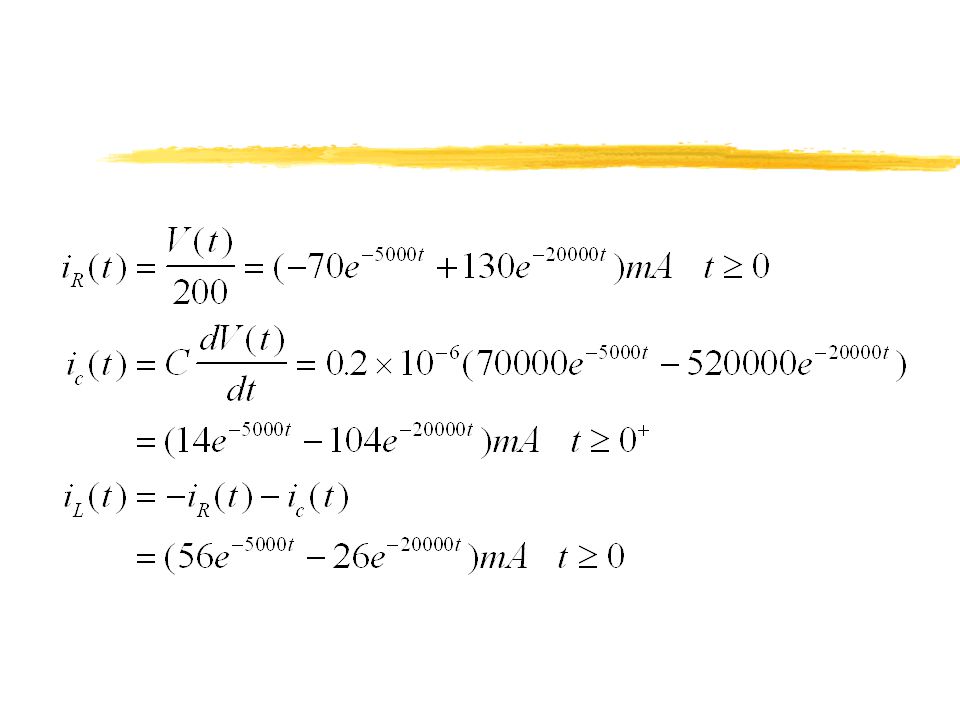
EXAMPLE iL I0 iR + + Fin V(t), if R=200 , L=50 mH, and C=0.2 F. V0=12V, I0=30 mA. ic L R V0 V C
, if R=200 , L=50 mH, and C=0.2 F. V0=12V, I0=30 mA. ic L R V0 V C")
13
From the previous example, we determined s1=-5000 rad/s and s2=-20000 rad/s. Then

16
THE UNDERDAMPED RESPONSE
When 02>2, the roots of the characteristic equation are complex, and the response is underdamped. d is called the damped radian frequency.

17
A1 and A2 are complex conjugates
A1 and A2 are complex conjugates. Therefore, their sum is a real number and their difference is imaginary. Then j(A1-A2) is also a real number. Denoting B1=A1+A2, and B2=j(A1-A2)
 is also a real number. Denoting B1=A1+A2, and B2=j(A1-A2)")
18
DAMPING FACTOR The trigonometric functions indicate that the response is oscillatory; that is, the voltage alternates between positive and negative values. The rate at which the voltage oscillates is fixed with d. The rate at which the amplitude decreases is determined by . Because determines how quickly the amplitude decreases, it is called as the damping factor. If there is no damping, =0 and the frequency of oscillations is 0. When there is a dissipative element, R, in the circuit, is not zero and the frequency of oscillations is, d, less than 0. Thus, when is not zero, the frequency of oscillation is said to be damped.

19
EXAMPLE iL I0 iR + + Find V(t) if R=20 k, L=8H, C=0.125F, V0=0, and I0= mA ic L R V0 V C
 if R=20 k, L=8H, C=0.125F, V0=0, and I0= mA ic L R V0 V C")
20
V(0+)=V0=0, then iR(0+)=V(0+)/R=0.
ic(0+)=-iL(0+)=12.25 mA
=-iL(0+)=12.25 mA.")
21
THE CRITICALLY DAMPED RESPONSE
The second-order circuit is critically damped when 2=02. The two roots of the characteristic equation are equal For a critically damped circuit, the solution takes the following form D1 and D2 are constant which must be determined using the initial conditions V(0+) and dV(0+)/dt
 and dV(0+)/dt.")
22
EXAMPLE iL I0 iR + + Determine the value of R for a critically damped response when, L=8H, C=0.125F, V0=0, and I0= mA ic L R V0 V C From the previous example 02=106. Then Again, from the previous example V(0+)=0 and dV(0+)/dt=98000 V/s Then D1=0 and D2=98000 V/s.
=0 and dV(0+)/dt=98000 V/s Then D1=0 and D2=98000 V/s.")
23
THE STEP RESPONSE OF A PARALLEL RLC CIRCUIT
ic iL iR + t=0 I L R V C

24
The equation describing the step response of a second-order circuit is a second-order differential equation with constant coefficients and with a constant forcing function. The solution of this differential equation equals the forced response which is in the same form of the forcing function (constant for a step input) plus a response function identical in form to the natural response. Thus, the solution for the inductor current is in the form
 plus a response function identical in form to the natural response. Thus, the solution for the inductor current is in the form.")
25
EXAMPLE ic iL iR + C=25nF, L=25mH, R=400 The initial energy in the circuit is zero. I=24 mA. Find iL(t) t=0 I L R V C Since there is no initial energy in the circuit, iL(0+)=0 and V(0+)=0 V(0+)=L[diL(0+)/dt]=0, then diL(0+)/dt=0 Overdamped circuit
=0 and V(0+)=0. V(0+)=L[diL(0+)/dt]=0, then diL(0+)/dt=0. Overdamped circuit.")
26
As t , circuit reaches dc steady state where inductor is short and capacitor is open. All of the input current flows through the inductor. Then If=24 mA.

27
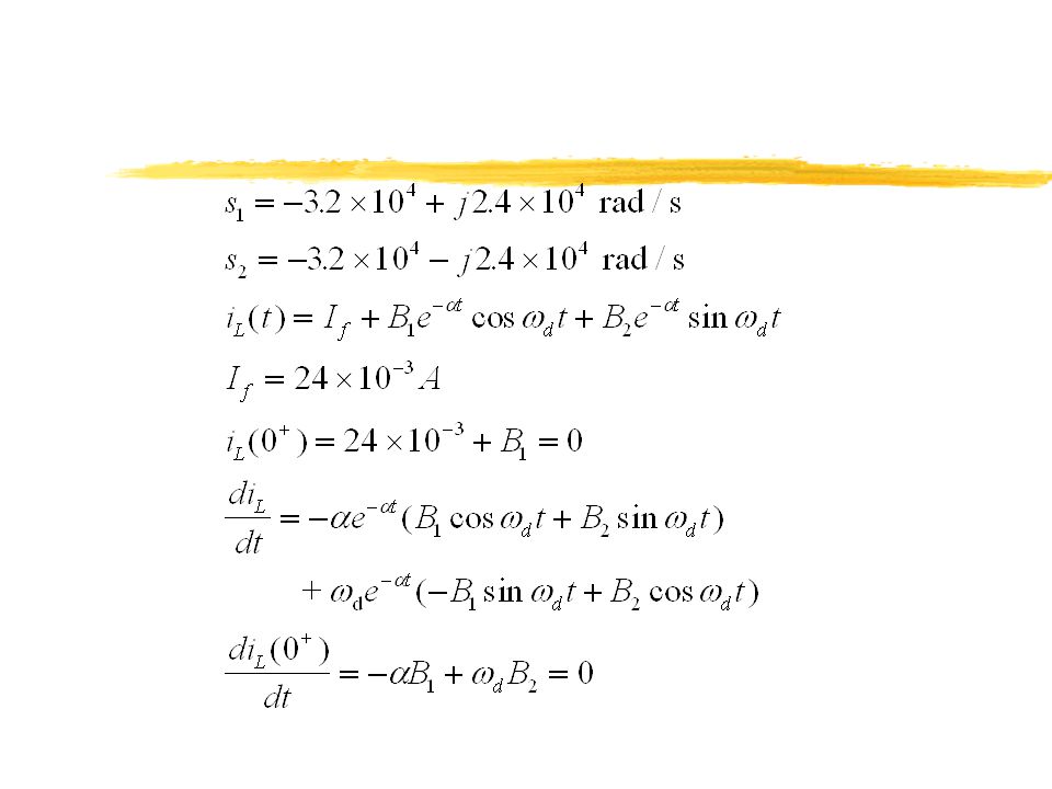
EXAMPLE: If the resistor in the circuit is increased to 625, find iL(t) in the circuit.
Since L and C remain fixed, resonant frequency has the same value. But neper frequency decreases to 3.2x10⁴ rad/s. With these values circuit is underdamped with complex conjugate roots.

29
EXAMPLE: Find iL(t) if R=500
The resonant frequency remains the same, but neper frequency becomes 4x10⁴ rad/s. These values correspond to critical damping. Roots of the characteristic equation are real and equal at s=-40000

32
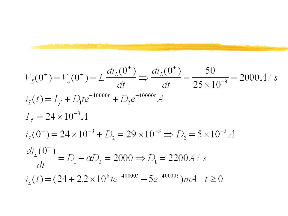
EXAMPLE C=25nF, L=25mH, R=500 The initial current in the inductor is 29 mA, the initial voltage across the capacitor is 50 V. I=24 mA. Find iL(t) and V(t) ic + iL iR + t=0 I L R V C Vc From the previous example, we know that this circuit is critically damped with s1=s2= rad/s
 and V(t) ic. + iL. iR. + t=0. I. L. R. V. C. Vc. From the previous example, we know that this circuit is critically damped with s1=s2= rad/s.")
35
THE NATURAL AND STEP RESPONSE OF A SERIES RLC CIRCUIT
+ C i V0

36
These equations are in the same form that of the equations for the parallel RLC circuit. Therefore, the solution will be overdamped, critically damped, or underdamped depending on relative magnitudes of the resonant frequency and neper frequency.

37
L t=0 R + + VR + VL + C V i Vc

38
100mH t=0 The capacitor is initially charged to 100V. At t=0, switch closes. Find i(t) and Vc(t) for t0 + + i Vc 560 100V

41
EXAMPLE t=0 + There is no initial stored energy in the circuit at t=0. Find Vc(t) for t0. 0.1H 280 + 48V 0.4F Vc

42
As t , circuit reaches dc steady state (inductor short, capacitor open). Thus, Vcf=48V
. Thus, Vcf=48V")
44
A CIRCUIT WITH TWO INTEGRATING AMPLIFIERS
+ Vg + Vo1 + + Vo + Assuming ideal opamps, find the relation between Vo and Vg

46
EXAMPLE 0.1F 1F 250k 5V 500k 9V + Vg + Vo1 + + Vo + -5V -9V
No energy is stored in the circuit when the input voltage Vg jumps instantaneously from 0 to 25 mV. Derive the expression for Vo(t) for 0 ttsat. How long is it before the circuit saturates?
 for 0 ttsat. How long is it before the circuit saturates")
48
The second integrating amplifier saturates when Vo reaches 9V or t=3s
The second integrating amplifier saturates when Vo reaches 9V or t=3s. But it is possible that the first opamp saturates before t=3s. To explore this possibility use the following equation Thus, at t=3s, Vo1=-3V. The first opamp does not reach saturation at t=3s. The circuit reaches saturation when the second amplifier saturates.

49
TWO INTEGRATING AMPLIFIERS WITH FEEDBACK RESISTORS
Rb + Vg + Vo1 + + Vo + The reason that the op amp saturates in the integrating amplifier is the feedback capacitor’s accumulation of charge. To overcome this problem, a resistor is placed in parallel with each feedback capacitor.

52
The characteristic equation is
The roots of the characteristic equation are real

53
EXAMPLE The parameters of the circuit are Ra=100 k, Rb=25 k, R1=500 k, R2=100 k, C1=0.1F, and C2=1F. The power supply of each op amp is 6V. The input voltage jumps from 0 to 250 mV at t=0. No energy is stored in the feedback capacitors at the instant the input is applied. Find Vo(t) for t0.
 for t0.")
54
The characteristic equation is s2+30s+200=0. Then
s1=-20 rad/s and s2=-10 rad/s. The final values of the output is the input voltage times the gain of each stage, because capacitors behave as open circuits as t

Similar presentations


 LC circuits and Oscillation Frequency>")


 Prof. Phillips April 7, 2003.>")

