Download presentation
Presentation is loading. Please wait.

1
EUSART Serial Communication

2
UART Universal Asynchronous Receiver/Transmitter
Receive: Convert serial to parallel (SIPO) Transmit: Convert parallel to serial (PISO) Asynchronous: No clock; bytes sent in chunks. Start (0) and stop (1) signal for each byte
 Transmit: Convert parallel to serial (PISO) Asynchronous: No clock; bytes sent in chunks. Start (0) and stop (1) signal for each byte.")
3
EUSART Enhanced Universal Synchronous / Asynchronous Receiver/Transmitter Synchronous: Constant stream of data matched with clock signal. More efficient, no start/stop framing required. Enhanced: Advanced features Sleep mode/auto-wake Calculate incoming baud rate Error Detection Full-duplex asynchronous, Half-duplex synchronous 8 or 9 bit character length

4
Flip-Flop Flip-flops store a single bit of data.
SR NOR latch: Simplest type of flip flop.

5
D Flip-Flop Similar function, but uses clock to feed Data signal to Q in time with clock cycle.

6
Receive Shift Register (RSR): Cascade of flip-flops
Data written serially by shifting. Upon filling register, all bits read simultaneously on clock cycle.

7
Transmit Altered shift register (TSR) reverses process.
All bits written to register simultaneously. Bits shift to next flip-flop on cycles. Last bit feeds output.

8
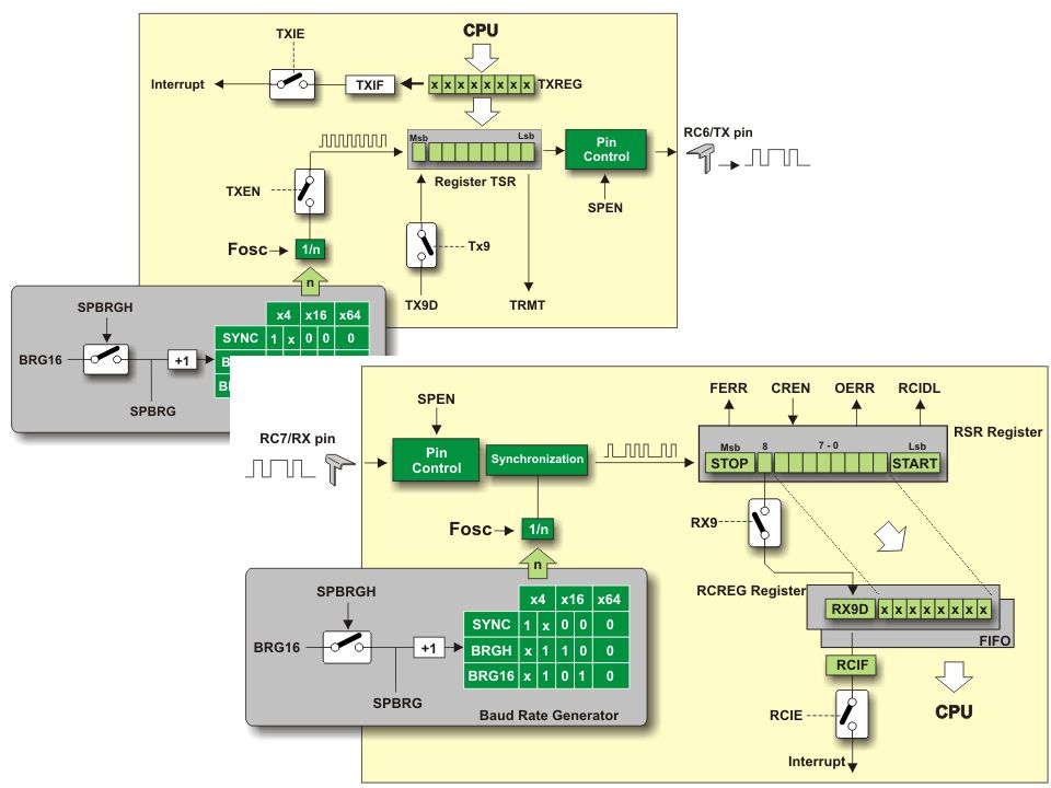
Registers TXSTA & RCSTA: Status registers. TSR & RSR: Shift registers.
Set modes. TSR & RSR: Shift registers. Not directly accessible. TXREG & RCREG: Container for transmitted data. BAUDCTL: 8-bit Baud Rate Control Register. SPBRG & SPBRGH: 16-bit Baud Rate Generator.

9
TXSTA – Transmit Status Register
CSRC - Clock Source Select bit - determines clock source. It is used only in synchronous mode. 1 - Master mode. Clock is generated internally from Baud Rate Generator 0 - Slave mode. Clock is generated from external source. +TX9 - 9-bit Transmit Enable bit 1 - 9-bit data transmission via EUSART system 0 - 8-bit data transmission via EUSART system. *TXEN - Transmit Enable bit *1 - Transmission enabled 0 - Transmission disabled. *SYNC - EUSART Mode Select bit 1 - EUSART operates in synchronous mode 0 - EUSART operates in asynchronous mode. SENDB - Send Break Character bit is only used in asynchronous mode and only in case it is required to observe LIN bus standard. 1 - Sending Break character is enabled 0 - Break character transmission is completed. *BRGH - High Baud Rate Select bit determines baud rate in asynchronous mode. It does not affect EUSART in synchronous mode. 1 - EUSART operates at high speed 0 - EUSART operates at low speed. TRMT - Transmit Shift Register Status bit 1 - TSR register is empty 0 - TSR register is full. TX9D - Ninth bit of Transmit Data can be used as address or parity bit.

10
RCSTA – Receive Status Register
*SPEN - Serial Port Enable bit *1 - Serial port enabled. RX/DT and TX/CK pins are automatically configured as input and output respectively 0 - Serial port disabled. +RX9 - 9-bit Receive Enable bit 1 - Receiving 9-bit data via EUSART system 0 - Receiving 8-bit data via EUSART system. SREN - Single Receive Enable bit is used only in synchronous mode when the microcontroller operates as master. 1 - Single receive enabled 0 - Single receive disable. *CREN - Continuous Receive Enable bit acts differently depending on EUSART mode. Asynchronous mode: *1 - Receiver enabled 0 - Receiver disabled. Synchronous mode: *1 - Enables continuous receive until the CREN bit is cleared 0 - Disables continuous receive. +ADDEN - Address Detect Enable bit is only used in address detect mode. 1 - Enables address detection on 9-bit data receive 0 - Disables address detection. The ninth bit can be used as parity bit. ~FERR - Framing Error bit 1 - On receive, Framing Error is detected 0 - No framing error. ~OERR - Overrun Error bit. 1 - On receive, Overrun Error is detected 0 - No overrun error. RX9D - Ninth bit of Received Data can be used as address or parity bit.

11
BAUDCTL – Baud Rate Control Register
*Bit 7: ABDOVF — Flag bit indicates time of overflow; sets rate. 1 - Auto-baud timer overflowed 0 - Auto-baud timer did not overflow. Bit 6: RCIDL — Idle/Sleep; only used in asynchronous mode. 1 - Receiver is idle 0 - START bit has been received and receiving is in progress. Bit 4: SCKP Synchronous: indicate which Idle state is used for the data Clock (CK) 1 - Synchronization on rising edge of the clock 0 - Synchronization on falling edge of the clock. Asynchronous: indicate transmit polarity. 1 - Transmit inverted data to the RC6/TX/CK pin 0 - Transmit non-inverted data to the same pin. *Bit 3: BRG16 — Enable 16-bit 1 – Enable 16-bit (disables BAUDCTL from setting rate). 0 – Disable 16-bit mode. Bit 1: WUE — Auto-wake/Interrupt 1 - Receiver waits for a falling edge on the RC7/RX/DT pin to wake from sleep. 0 - Receiver operates normally. Bit 0: ABDEN — Reset Baud – auto-baud recalculation on next character (async only) 1 - Auto-baud detect mode is enabled. Bit is automatically cleared on baud rate detect. 0 - Auto-baud detect mode is disabled.
 1 - Synchronization on rising edge of the clock. 0 - Synchronization on falling edge of the clock. Asynchronous: indicate transmit polarity. 1 - Transmit inverted data to the RC6/TX/CK pin. 0 - Transmit non-inverted data to the same pin. *Bit 3: BRG16 — Enable 16-bit. 1 – Enable 16-bit (disables BAUDCTL from setting rate). 0 – Disable 16-bit mode. Bit 1: WUE — Auto-wake/Interrupt. 1 - Receiver waits for a falling edge on the RC7/RX/DT pin to wake from sleep. 0 - Receiver operates normally. Bit 0: ABDEN — Reset Baud – auto-baud recalculation on next character (async only) 1 - Auto-baud detect mode is enabled. Bit is automatically cleared on baud rate detect. 0 - Auto-baud detect mode is disabled.")
12
Transmitter Set Baud: BRGH (TXSTA) & BRG16 (BAUDCTL)
TXEN = 1: Enable transmitter (TXSTA) SPEN = 1: Enable Serial Port (RCSTA) TX/CK pin is output SYNC: Synchronous-1 or Asynchronous-0 (TXSTA) TXREG: Write data to be sent here. TSR: Data automatically transferred to TSR shift register from which it is serialized and output. TXREG is cleared and awaits new data to repeat transmission.
 SPEN = 1: Enable Serial Port (RCSTA) TX/CK pin is output. SYNC: Synchronous-1 or Asynchronous-0 (TXSTA) TXREG: Write data to be sent here. TSR: Data automatically transferred to TSR shift register from which it is serialized and output. TXREG is cleared and awaits new data to repeat transmission.")
13
Receiver Set Baud: BRGH (TXSTA) & BRG16 (BAUDCTL)
CREN = 1: Enable receiver (RCSTA) SPEN = 1: Enable Serial Port (RCSTA) Input to RX/DT pin SYNC: Synchronous-1 or Asynchronous-0 (TXSTA) RX/DT serial pin data sent to RSR shift register. RCREG: 8 or 9-bit data from RSR automatically transferred here. Input data will be readable from RCREG register.
 SPEN = 1: Enable Serial Port (RCSTA) Input to RX/DT pin. SYNC: Synchronous-1 or Asynchronous-0 (TXSTA) RX/DT serial pin data sent to RSR shift register. RCREG: 8 or 9-bit data from RSR automatically transferred here. Input data will be readable from RCREG register.")
14
TX/RC Interrupts Interrupt represents each successive byte. Transmit
Enable TXIE or RCIE to enable interrupt. Transmit When TXREG is empty, TXIF flag is set. FlagInterrupt: Send to TXREG TXIF is reset until TXREG is re-emptied. Receive Upon filling RCREG, RCIF flag is set. FlagInterrupt: Read RCREG RCIF flag is reset until RCREG is re-filled.

16
Example Code Utilizing data received by EUSART.
Interrupt Routine If RCIF flag is set, read EUSART (RCREG). Flag code when read. Main function: Enable interrupt. Endless loop. If flagged, read new data and place in array.
. Flag code when read. Main function: Enable interrupt. Endless loop. If flagged, read new data and place in array.")
17
Address Detection ADDEN bit (RCSTA) determines address size.
ADDEN = 1 allows 9-bit, excludes 8-bit ADDEN = 0 disables address detection

18
Errors Framing Error: In asynchronous mode Overrun Error
Stop bit not received at expected time. Enables FERR bit (RCSTA). Interrupt not necessarily generated, simply informs of possibly incorrect data. FERR is cleared by once data is read. Overrun Error RCREG is FIFO and can hold no more than two bytes. Third byte while RCREG is still full Enables OERR bit (RCSTA). No more data received until OERR is manually cleared (clear CREN). Manual clearing of SPEN (RCSTA) will reset entire EUSART.
. Interrupt not necessarily generated, simply informs of possibly incorrect data. FERR is cleared by once data is read. Overrun Error. RCREG is FIFO and can hold no more than two bytes. Third byte while RCREG is still full. Enables OERR bit (RCSTA). No more data received until OERR is manually cleared (clear CREN). Manual clearing of SPEN (RCSTA) will reset entire EUSART.")
19
Reference http://ww1.microchip.com/downloads/en/AppNotes/00944A.pdf

Similar presentations
 Michael LennardZachary PetersBao Nguyen.>")


 Lecturer: Hui Wu Session 1, 2005.>")


>")


 Kevin Stuart Matt Betts March 27, 2007 ME 6405, Sp 07.>")
>")


>")