Download presentation
Presentation is loading. Please wait.

1
Digital Logic Design Lecture 29

2
Announcements Homework 9 due today Please fill out Course Evaluations online. Final exam will be on Thursday, Dec. 18 10:30- 12:30 in CHE 2118 (our regular classroom). Shang will hold a review for the final exam in AVW 2120 on Friday, 12/12 from 11am-12:15pm. Information about final exam (including review problems for the review session) now up on course webpage.
. Shang will hold a review for the final exam in AVW 2120 on Friday, 12/12 from 11am-12:15pm. Information about final exam (including review problems for the review session) now up on course webpage..")
3
Agenda Last Time: – State Table Reduction (7.4) – The State Assignment Problem (7.5) This Time: – Finish The State Assignment Problem (7.5) – Completing the Design of Clocked Synchronous Sequential Networks (7.6)
 – The State Assignment Problem (7.5) This Time: – Finish The State Assignment Problem (7.5) – Completing the Design of Clocked Synchronous Sequential Networks (7.6)")
4
Simplest Approach

5
Next-State and Output K-maps

6
Guidelines for Obtaining State Assignments Rule I: Two or more present states that have the same next state for a given input combination should be made adjacent. Rule II: For any present state and two adjacent input combinations, the two next states should be made adjacent. Rule III: Two or more present states that produce the same output symbol, for a given input combination should be made adjacent (only needs to be done for one of the two output symbols).
..")
7
Example

9
Next consider Rule III: Look at present states that produce output symbol 1 on the same input.

10
State Assignment Map K-map for the state variables in which each cell of the map denotes a combination of the binary digits that can be assigned to a state of the sequential network. A (B,G) 2x (C,F) (D,H) 2x (A,E) (A,B) (B,C) 3x (D,E) (F,G) 2x (D,H) (D,F) (E,G) I.S.
 2x (C,F) (D,H) 2x (A,E) (A,B) (B,C) 3x (D,E) (F,G) 2x (D,H) (D,F) (E,G) I.S..")
11
State Assignment Map K-map for the state variables in which each cell of the map denotes a combination of the binary digits that can be assigned to a state of the sequential network. AB (B,G) 2x (C,F) (D,H) 2x (A,E) (A,B) (B,C) 3x (D,E) (F,G) 2x (D,H) (D,F) (E,G) I.S.
 2x (C,F) (D,H) 2x (A,E) (A,B) (B,C) 3x (D,E) (F,G) 2x (D,H) (D,F) (E,G) I.S..")
12
State Assignment Map K-map for the state variables in which each cell of the map denotes a combination of the binary digits that can be assigned to a state of the sequential network. ABG (B,G) 2x (C,F) (D,H) 2x (A,E) (A,B) (B,C) 3x (D,E) (F,G) 2x (D,H) (D,F) (E,G) I.S.
 2x (C,F) (D,H) 2x (A,E) (A,B) (B,C) 3x (D,E) (F,G) 2x (D,H) (D,F) (E,G) I.S..")
13
State Assignment Map K-map for the state variables in which each cell of the map denotes a combination of the binary digits that can be assigned to a state of the sequential network. ABG C (B,G) 2x (C,F) (D,H) 2x (A,E) (A,B) (B,C) 3x (D,E) (F,G) 2x (D,H) (D,F) (E,G) I.S.
 2x (C,F) (D,H) 2x (A,E) (A,B) (B,C) 3x (D,E) (F,G) 2x (D,H) (D,F) (E,G) I.S..")
14
State Assignment Map K-map for the state variables in which each cell of the map denotes a combination of the binary digits that can be assigned to a state of the sequential network. ABGE C (B,G) 2x (C,F) (D,H) 2x (A,E) (A,B) (B,C) 3x (D,E) (F,G) 2x (D,H) (D,F) (E,G) I.S.
 2x (C,F) (D,H) 2x (A,E) (A,B) (B,C) 3x (D,E) (F,G) 2x (D,H) (D,F) (E,G) I.S..")
15
State Assignment Map K-map for the state variables in which each cell of the map denotes a combination of the binary digits that can be assigned to a state of the sequential network. ABGE CD (B,G) 2x (C,F) (D,H) 2x (A,E) (A,B) (B,C) 3x (D,E) (F,G) 2x (D,H) (D,F) (E,G) I.S.
 2x (C,F) (D,H) 2x (A,E) (A,B) (B,C) 3x (D,E) (F,G) 2x (D,H) (D,F) (E,G) I.S..")
16
State Assignment Map K-map for the state variables in which each cell of the map denotes a combination of the binary digits that can be assigned to a state of the sequential network. ABGE CFD (B,G) 2x (C,F) (D,H) 2x (A,E) (A,B) (B,C) 3x (D,E) (F,G) 2x (D,H) (D,F) (E,G) I.S.
 2x (C,F) (D,H) 2x (A,E) (A,B) (B,C) 3x (D,E) (F,G) 2x (D,H) (D,F) (E,G) I.S..")
17
State Assignment Map K-map for the state variables in which each cell of the map denotes a combination of the binary digits that can be assigned to a state of the sequential network. ABGE HCFD (B,G) 2x (C,F) (D,H) 2x (A,E) (A,B) (B,C) 3x (D,E) (F,G) 2x (D,H) (D,F) (E,G) I.S.
 2x (C,F) (D,H) 2x (A,E) (A,B) (B,C) 3x (D,E) (F,G) 2x (D,H) (D,F) (E,G) I.S..")
18
State Assignment Map K-map for the state variables in which each cell of the map denotes a combination of the binary digits that can be assigned to a state of the sequential network.

19
Transition Table Using the state assignment map and state table, a transition table is constructed.

20
Transition Table K-maps for next-state and output functions.

21
Next-State and Output K-maps

22
Unused States

23
Approach 1: – The corresponding entries in the K-maps are don’t cares. – This provides greater flexibility when obtaining minimal expressions for next-state and output functions. Approach 2: – The network may enter one of the unused states (when first turned on, due to noise, hardware failure, etc.) – It may be desirable that the network go to some well- defined state at the end of the clock period. – Next state entries for each of the unused states should be specified.
 – It may be desirable that the network go to some well- defined state at the end of the clock period. – Next state entries for each of the unused states should be specified..")
24
Illustrating Approach 1

25
Illustrating Approach 2

26
Completing the Design Choose which type of clocked flip-flops should be used for memory. Depending on this choice, appropriate excitation signals must be generated by the combinational logic that precedes the input terminals of the flip-flops. Excitation table can be constructed from transition table once flip-flop type is selected.

27
Application tables for Flip-Flops

28
From Transition Table to Excitation Table

29
Completing the Design with D-flip-flops

30
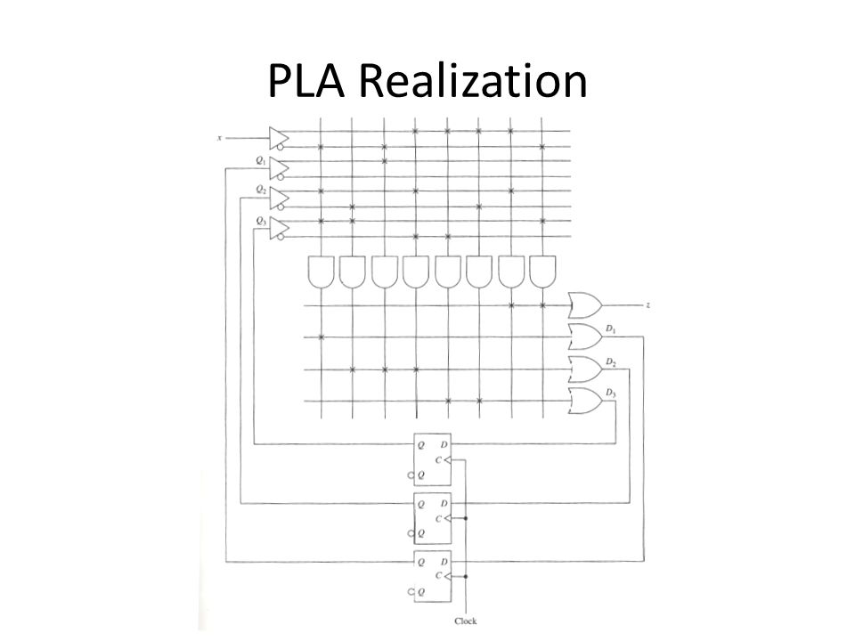
Realizations using PLDs

31
PROM Realization

32
PLA Realization

34
Additional Example

35
From Transition Table to Excitation Table

36
K-Maps

38
Additional Example

39
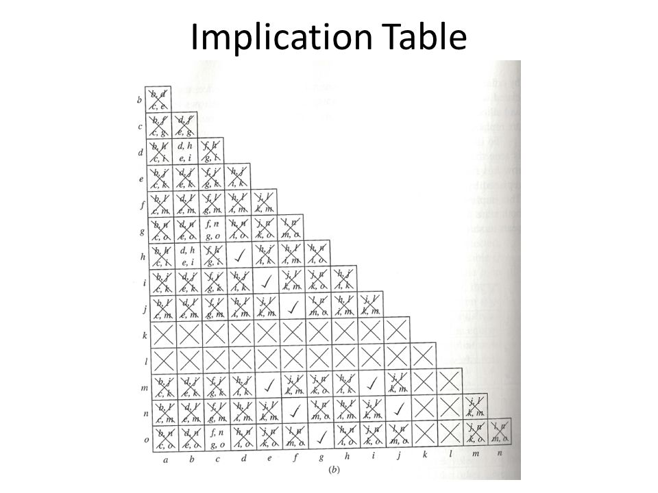
Recall 0110/1001 Sequence Recognizer

40
Alternative State Table

41
Implication Table

Similar presentations


>")


 =D A = AX + BX B(t+1) =D B = AX Y = AX + BX.>")
 The slides included herein were taken from the.>")


