Download presentation
Presentation is loading. Please wait.

1
BUILDING CONSTRUCTION

2
INTRODUCTION As architects and the building industry continue to design and build structures that vary in type, design, materials, and building methods, it has become increasingly important that members stay familiar with both basic and new concepts of building construction. Construction methods are constantly being replaced by new and more efficient and cost effective methods to construct buildings.

3
SUBSURFACE INVESTIGATIONS
The purpose of characterizing subsurface conditions is to determine if the soils beneath a facility exhibit properties that ensure the facility will remain stable under static and seismic conditions during construction and operation and after it is closed. A complete comprehensive soil stratigraphy should be developed that will adequately characterize the lateral and vertical extent of all soil units beneath the proposed facility. Characteristics to be measured include, but are not limited to, shear strength, liquefaction potential, compressibility, phreatic surface elevations and the water content of the soil materials

4
SITE INVESTIGATION

5
SITE INVESTIGATION Site Investigation is the gathering of the information about the proposed location of a project, e.g. highway or buildings.

6
The Purpose of Site Investigation
The site investigation is aimed at providing sufficient reliable subsurface information for most economical, satisfactorily safe foundation for the proposed structure. The site investigation should reveal sufficient subsurface information for the design and construction of a stable foundation safe from both collapse and detrimental movements.

7
The Scope of Site Investigation
Topography Soil profile Ground-water condition

8
The Stages of Site Investigation
In general, a site investigation program should comprise four stages, i.e. : Desk study and site reconnaissance, Preliminary ground investigation, Detailed ground investigation

9
Desk study and site reconnaissance
The desk study is the first stage of the site investigation process which involves researching the site to gain as much information as possible, both geological and historical. A good starting point is to use Ordinance survey maps which allow the selection of the site by obtaining accurate grid reference through the maps. In addition to present maps, old maps are used to gain historical information such as former uses of the site; concealed mine workings; in filled ponds; old pits; disused quarries; changes in potential landslide areas, etc.

10
The source of information that useful in desk study:
Geological map Geological maps are probably most important source of information as these give and excellent indication of the sort of ground conditions like to be encountered. Aerial photography Aerial photography is another extremely useful source of information on topography and ground conditions. Records of previous investigation Records of previous investigation reports also helpful in a desk study. The many sources of site investigation data include previous company and Public Works Department.

11
The reconnaissance phase of a site investigation
This site investigation is done through a site visit or walk-over survey. Important evidences to look for are site lay out, surface condition, climate and hazards water levels, etc. Generally the desk study and reconnaissance is aimed at the feasibility study of the being planned. If the desk study shows that the site is feasible for the structure, then preliminary investigation should follows.

12
Preliminary Investigation
Preliminary Investigation is aimed at predicting the geological structures, soil profiles and the position of ground water table by geophysical method or by making a few boreholes. The investigation should give information on the existence on ground structures that may need closer examination: for example, The extent of disturbed strata, The location and extend of natural cavities and mine workings. Fractures and river crossings or alluvial areas that may have buried soft material or pet, their liability to cause subsidence, surface movements or instability Information on suitability of soil for fills work, ground water condition and the possibility of flooding should be provided at this stage.

13
Detailed Investigation
At this stage, the extent of the test, number and depth of boreholes, selection of appropriate equipment for field testing and the choice of laboratory testing are made. Soil exploration consists of three steps: Boring and in-situ testing, Sampling, Laboratory testing.

14
Monitoring Monitoring during construction and maintenance period is required whether the expectations of the proceeding investigation have been realize. No one can ensure that the soil parameters used for design is the most representative of the soil conditions at the site unless the response is observed. Field observation can help for early diagnosis and redemption of any problem that might be encountered during construction. Among the measurement made during the monitoring stage are the settlement, displacement, deformation, inclination, and pore water pressure.

15
Steps of Soil Exploration
BORING Soil borings are the most common method of subsurface exploration in the field. A bore hole is used to determine the nature of the ground in a qualitative manner and then recover disturbed and undisturbed samples for quantitative examination. Some types of borings are hand/mechanical auger borings, wash borings, percussion drilling, rotary drilling, and core borings. An auger is a screw-like tool used to bore a hole. Some augers are operated by hand: others are power operated

16
Hand/Mechanical Auger
Hand augers may be used for boring to a depth of about 6 m. Power augers may be used for boring to a depth of about 10 to 30 m. As the hole is bored a short distance, the auger may be lifted to removed soil. The removed soil can be used for field classification and laboratory testing, but it must not be considered as an undisturbed soil sample. Power auger set with a drill rig can be used to obtain samples from deeper strata. Some rigs can be used to drill a hole to 100 m depth.

17
Wash Boring Wash borings consists of simultaneous drilling and jetting action. A hole is bored through a casing by using a drilling bit. Jetting action is accomplished by pumping water downward through the drilling bit to soften the soil. Samples taken using the wash boring methods are disturbed sample.

18
Percussion Drilling Percussion Drilling is the process of making boreholes by striking the soil then removing it. The tools are repeatedly dropped down the borehole while suspended by wire from the power winch. Water is circulated to bring the soil cuttings to the ground surface. A casing and a pump are required to circulate the water.

19
Rotary Drilling Rotary Drilling uses rotation of the drill bit with the simultaneous application of pressure to advance the hole. This method is the most rapid method of advancing a hole in soil and rock. Drilling mud may be needed to prevent soil cave-in. Sample obtained from drilling by this method is relatively less disturbed as compared to samples obtained by the preceding methods.

20
Auger boring Power drills
Boring tools Auger boring Power drills

21
SOIL BORING

22
GENERAL REQUIREMENTS OF FOUNDATION:-
The only requirement is that it should not fail i.e. it should work efficiently under all conditions of working. Failures are of two types; Bearing capacity failure. Excessive settlement. So the foundation must be safe against both the above failures and also it must be properly located. This proper orientation of a foundation can be well explained with the following example;

23
GENERAL REQUIERMENT FOR ANY DESIGN:-
By design we always mean that what are the stresses acting on a particular member and the corresponding size of the members that theses stresses can be carried out efficiently. The general principle of the design is to design the structure into different elements. We are going to discus only one element, i.e. foundation. Designing is done in two stages; Analysis Sizing.

24
STRUCTURAL ANALYSIS:-
In first step of every design, we analyze the state of stress and see the strain due to these stresses. In analysis we see the type of loading, type of strain and the modes of failure. In foundation design these stresses are called as bearing capacity and strains as settlements. So in foundation design, analysis means the determination of bearing capacity and settlement. We have various methods both field tests and empirical methods for finding bearing capacity and settlements.

25
SIZING:- Step # 01(Material Selection)
Before going to sizing, we decide about the material to be used in the construction of the footing e.g. wood, concrete, steel etc. it depends upon the availability of the material and economy. The cost of project mainly depends on it. Since the foundation system is a very complex system, the construction material is not homogeneous. It consists of soil and other materials (wood, concrete etc.). here we will take concrete only.
. here we will take concrete only.")
26
SIZING:- Step # 02 (Dimensioning)
Now using the data from analysis and the material selected the dimension are chosen (i.e. thickness, width, depth of pad) and the design is completed. Step # 03 (Documentation) Now the design is represented in the form of drawings and the construction specifications (i.e. procedure, problems and solutions) are also mentioned.
 and the design is completed. Step # 03 (Documentation) Now the design is represented in the form of drawings and the construction specifications (i.e. procedure, problems and solutions) are also mentioned.")
27
STRUCTURAL DESIGN:- In design that takes into account the technical aspects related to concrete is called as Structural Design.

28
GEOTECHNICAL DESIGN OF FOUNDATION:-
For the geotechnical deign of the foundation the following steps are observed; The choice of foundation system between deep and shallow foundation. Fix the vertical location of the foundation i.e. Df in case of shallow and ‘L’ in case of pile foundation. Bearing capacity and settlement analysis and choose an appropriate value of the design pressure “qd”, bearing capacity equation and settlement equation. Using the information of (3) fix the dimensions in the plane i.e. ‘B’ & ‘L’. Evaluate the construction problems such as the problem of excavation, dewatering, water proofing and water tightening, deterioration of concrete and suggest their remedial measures.
 fix the dimensions in the plane i.e. ‘B’ & ‘L’. Evaluate the construction problems such as the problem of excavation, dewatering, water proofing and water tightening, deterioration of concrete and suggest their remedial measures.")
29
STEPS OF GEO-TECHNICAL DESIGN
Selection of the type of foundation system. Fix the vertical location i.e. Df of the foundation. Bearing Capacity and Settlement Analysis and from this a suitable value of “qd” i.e. the design pressure. The dimensions in plane (B & L) Construction Specification.
 Construction Specification.")
30
Physical Requirements:-
Following are the different physical requirements; Footing should be below Top organic soil. Susceptible zone. Surface erosion zone. Frost line. Scour depth. There should be the specified edge distance i.e. Level Difference

31
Step No. 1:-Selection of the foundation type:-
For this the following steps are kept in mind Type of structure and its requirements Sub soil profile at the site. Overall impact on the environment. Relative cost and construction facilities. Broadly speaking the types of foundation are; Shallow Foundations. Deep Foundations. Floating Foundations.

32
Step No. 2:- DEPTH OF FOUNDAION;
For depth of foundation, the following two considerations are kept in mind, Mechanical Consideration. Physical Consideration. In mechanical consideration we check Bearing Capacity and Settlement. For Bearing Capacity Terzaghi’s equation (for general share failure) is applied i.e. qult = ScCNc + γ Df Nq + Sγ0.5γBNγ From this equation it is clear that with the same soil, the properties remain the same and if ‘b’ is kept constant, then the Bearing Capacity goes on increasing by increasing the depth, but economy is also given due regards.
 is applied i.e. qult = ScCNc + γ Df Nq + Sγ0.5γBNγ. From this equation it is clear that with the same soil, the properties remain the same and if ‘b’ is kept constant, then the Bearing Capacity goes on increasing by increasing the depth, but economy is also given due regards.")
33
Step No. 3:- BEARING CAPACITY ANALYSIS:-
FOR BEARING CAPACITY:- qult = CNc + γDfNq + 0.5γBNγ qult / F.O.S = safe gross B.C or safe B.C (qult )Net = CNc+ γDf (Nq-1) + 0.5γBNγ (qult )Net / F.O.S = safe net B.C For square footing and circular footing; qult = 1.3CNc + γDfNq + 0.5γBNγ For pure clay Nc =5.7, Nq=1 & Nγ=0 B.C calculated by these equations is called B.C w.r.t. shear.
Net = CNc+ γDf (Nq-1) + 0.5γBNγ. (qult )Net / F.O.S = safe net B.C. For square footing and circular footing; qult = 1.3CNc + γDfNq + 0.5γBNγ. For pure clay. Nc =5.7, Nq=1 & Nγ=0. B.C calculated by these equations is called B.C w.r.t. shear.")
35
Masonry Stone Bricks Terra cotta Mortars Plasters

36
Stone 1. Types of building stones a. Igneous b. Sedimentary
c. Metamorphic 2. Cutting and shaping techniques 3. Stone finishes 4. Types of walls

37
1. Types of building stones
a. Igneous b. Sedimentary c. Metamorphic

38
Rock cycle Metamorphic Igneous Erosion & Precipitation
Heat Sedimentary Heat & Pressure Metamorphic

39
Igneous rocks Cobble Hill granite quarry, Barre, VT
Asher and Adams Pictorial Album of American Industry, 1876 Cobble Hill granite quarry, Barre, VT

40
Granites

41
Barre white granite

42
Sedimentary Limestones

43
Limestone Indiana limestone Trenton limestone

44
Trenton limestone St. Marc des Carriers, Quebec

45
Sandstone Longmeadow sandstone Billings Library, Burlington, VT

46
Sandstone to Quartzite
Metamorphic Sandstone to Quartzite Limestone to Marble Shale to Slate

47
Quartzite Redstone quarry, Burlington, VT

48
Monkton Quartzite redstone

49
Marble

50
Slate

51
Hand sawing marble, Diderot, 1762

52
Steam channeling machine, 1891

53
Wire saw cutting granite

54
Stone plane

55
Stone Finishes

58
Cobble Ashlar

59
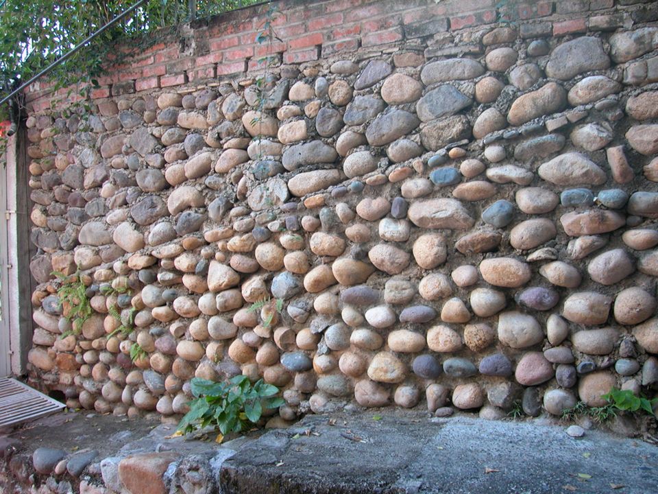
Rubble

66
Doors General Classifications Flush doors Panel doors
Smooth on both sides Mahogany or birch plywood Panel doors Heavy frame around perimeter Parts Stiles Rails Panels Louvers Stiles – vertical members Rails – horizontal members Panels – Thin material enclosed by stiles and rails

67
Exterior Doors Typical sizes Sloping sills to shed water
6’-8” tall by 1-3/4” thick Entry door minimum 3’-0” Insulated Sloping sills to shed water

68
Exterior Doors French doors Swinging doors Sliding doors Garage doors
Mullions and muntins between glass panes One large glass panes Individual, pairs, groups Garage doors Overhead One piece or sectional Widths Singles: 8’, 9’, 10’ Doubles: 15’,16’, 18’ Height generally 7’-0” Swinging doors Hinged Swing into the house Sliding doors Wood or metal frames Tempered glass Access to deck/patio Common widths 6’-0” 8’-0”

69
Interior Doors Standard sizes Standard widths Height: 6’-8”
Thickness: 1-3/8” Width: Varies based on 2” module Standard widths Entry: 3’-0” Bedrooms: 2’-6” Baths: 2’-0” or 2’-4” Closets: As large as possible

70
Interior Doors Bi-fold Sliding/Bypass
Set of two doors make up one unit Hung on a track Popular for closets Sliding/Bypass Used in wide openings

71
Interior Doors Pocket doors Double-action Hung on a track
Slides into a wall cavity Frees floor space Packaged with framed pocket Double-action Spring hinge mounted Swings two ways One or two doors

72
Windows Purpose Admits light Provides fresh air and ventilation
Adds detail, balance, interest Visually enlarges interior space

73
Window Types Double-hung Horizontal sliding/gliding Casement
Two sashes slide up and down Most commonly used Horizontal sliding/gliding Two or more sashes slide horizontally Operates on a track Casement Hinged sashes; outward swing

74
Window Types Awning Hopper Fixed Sash hinged on top; swings outward
Allows open unit during rain Hopper Hinged sash on bottom; swings inward Allows for unusual shapes Fixed Do not open Combined with other windows

75
Window Types Bay and Bow Skylights Fixed or casement
Project from structure Bay windows offer traditional style Sides 450 or 300 Depth between 18” and 24” Roof structure Bow windows are in a circular pattern Skylights Built into roof Admit light

76
Door/Window Schedules
Marks placed on floor plan identify doors & windows Numbers or letters inside circles or polygons identify individual units Placed close to door & window symbols Same mark used for doors/windows with same size and characteristics

77
STAIRS AND STAIRCASES

78
Definition: Different parts of staircase:
Construction designed to bridge a large vertical distance, by dividing it into smaller vertical distances called steps. Different parts of staircase: STEP--Tread-Riser BALUSTRADE--Baluster-Handrail- Newel Post

80
Guide lines for fixing the dimensions
Rise (R) : 150mm to 180mm Tread (T) : 220 mm to 250 mm- for residential buildings. Rise (R) : 120 to 150 mm Tread (T) : 250 mm to 300 mm – for public buildings [T + 2R] : Between 500 mm to 650 mm The width of the stair 0.8 m to 1 m for residential building and 1.8 m to 2 m for public building.
 : 150mm to 180mm. Tread (T) : 220 mm to 250 mm- for residential buildings. Rise (R) : 120 to 150 mm. Tread (T) : 250 mm to 300 mm – for public buildings. [T + 2R] : Between 500 mm to 650 mm. The width of the stair. 0.8 m to 1 m for residential building and. 1.8 m to 2 m for public building.")
81
Guide lines for fixing the dimensions Contd…
The width of the landing is equal to the width of stairs. The number of steps in each flight should not be greater than 12 The pitch of the stair should not be more than 38 degrees. The head room measured vertically above any step or below the mid landing shall not be less than 2.1 m. The height of the balusters should be around 0.75 to 1 m. The space between two balusters should not be more than cm.

82
CLASSIFICATION Based on shape of plan: Stair Plans Straight staircase
“U” staircase “C” Staircase Stair Plans

83
Adjustable Staircase “L” Staircase Stair Plans

84
Based on shape Straight stairs Dog legged stairs
Open well or open newel stairs Geometrical stairs such as spiral, circular, etc. Free standing stair cases Bifurcated staircase

85
Some photos Dog legged SC Straight SC Geometric SC Bifurcated SC

86
Open Well or Newel stair cases
II- FLIGHT LANDING OPEN WELL OPEN WELL III- FLIGHT I- FLIGHT WITH INTERMEDIATE FLIGHT WITHOUT INTERMEDIATE FLIGHT

87
Types of staircases based on materials
Stainless steel Timber/Wood Glass Iron Aluminium Concrete

88
Central Carriage Glass SC
Concrete Bullnose SC

89
“U” Shaped SC Helix Spiral SC

90
Stepsure Winder System
Easier to negotiate than triangular winders Provides a spacious passing point Tuscan Staircase Characteristic to the Tuscan style are clean lines and strong visual elements such as steel balusters, cut stringers, with paint finishes that highlight clear-finished treads and continuous handrails. Tuscan stairs were often tiled over concrete.

91
Victorian Staircase Victorian staircases have a solid architecture style, strong on decoration, with large newel posts, elaborate turnings, and complex tread bracket designs. Elaborate handrail contours and patterns, handrails were often larger (80mm * 60mm) and continuous. Timbers are deep in colour, or are stained to a rich dark finish.
 and continuous. Timbers are deep in colour, or are stained to a rich dark finish.")
92
Different Designs of Balusters

93
Special Staircases: Some examples

94
Glass Staircases These are made by using stainless steel bars and brackets, and thick glass slabs as treads.

95
Disappearing Steps They work by having the frame of the stairs slide out from the wall, powered by hydraulic pistons, and having the stair planks fold over the frame one at a time. When finished, the stair frame slides back in the wall and the planks stand straight up, flush against the wall.

96
Scala Constrain del Bovolo, Venice
Spiral staircase used as facade

97
Staircase as a Sculpture
by Olafur Eliasson, 2004, Munich, Germany. These staircase are not a structural but just an aesthetic element of design

98
FLOORS AND FLOORINGS

99
After the foundations have been completed and the external walls constructed the construction of the floors commences. Floors construction

100
Function of a ground floor
To carry loads imposed on them. To prevent dampness rising from the ground into the building. To provide a degree of thermal insulation. To prevent growth of vegetable matter in the building. To provide a suitable wearing surface. Basically there are two types of ground floors:- solid floors and suspended floors.

101
Solid ground floor One in which the whole floor area is in contact with the subsoil. Comprised of three main components:- Hardcore The purpose of this is (a) To ensure consistent material over the whole floor area. (b) To reduce capillary action of moisture from the ground because of voids within the hardcore layer. (c) To make up levels after removing topsoil and reduced level excavation. (d) to provide a clean dry and firm working surface. The top of the hardcore should be blinded with a fine dust or sand to fill the voids, prevent grout loss from concrete and protect D.P.M. if placed in this position.
 To ensure consistent material over the whole floor area. (b) To reduce capillary action of moisture from the ground because of voids within the hardcore layer. (c) To make up levels after removing topsoil and reduced level excavation. (d) to provide a clean dry and firm working surface. The top of the hardcore should be blinded with a fine dust or sand to fill the voids, prevent grout loss from concrete and protect D.P.M. if placed in this position.")
102
Solid ground floor Damp proof membrane (DPM) An impervious layer to prevent moisture travelling through the floor to the inside of the building eg. polythene sheeting. Concrete bed This provides the solid level surface to which screeds and finishes can be applied.
 An impervious layer to prevent moisture travelling through the floor to the inside of the building eg. polythene sheeting. Concrete bed This provides the solid level surface to which screeds and finishes can be applied.")
103
Floor detail at junction with a cavity wall
1200 gauge polythene DPM Skirting 50 mm min Insulation Sand and Cement screed Sand and Cement screed DPC 150mm minimum above Ground level 100mm Concrete sub floor Ground level Hardcore

104
Square edge flooring 150mm wide and 20mm thick.
Timber floors Supporting wall Suspended timber floor joists are supported by the walls which transfer the load from the floor, through the wall to the foundations. The traditional method of providing a flooring surface on top of these joist’s was sawn timber boards which had square edges. These boards were butted together and nailed down unto the top of the joist. The quality of the flooring boards was improved by the addition of tongue and grooved joints. Square edge flooring 150mm wide and 20mm thick. Floor joist Supporting wall

105
Timber ground floors If timber ground floors are used ventilation must be provided beneath the floor construction. The reason for this ventilation is to prevent the moisture content of the timber rising above an unacceptable level (i.e.. 20%) which would create the conditions for possible fungal attack. Sheet materials such as plywood and chipboard are now the most popular coverings to floor joists. The most common size of sheets are mm x 2440mm. Floor joists are usually placed at 400mm centres. Joist spaced at 400mm centres. Plywood sheeting Positions for ventilation
 which would create the conditions for possible fungal attack. Sheet materials such as plywood and chipboard are now the most popular coverings to floor joists. The most common size of sheets are 1220mm x 2440mm. Floor joists are usually placed at 400mm centres. Joist spaced at 400mm centres. Plywood sheeting. Positions for ventilation.")
106
Suspended T beam concrete floor
Pre-stressed concrete floor beams cast in the shape of an inverted T Concrete blocks laid between T beams 100mm sand and cement screed on top of beam floor Pre-stressed concrete floor beams Pre-stressed T beam concrete floors were one of the first methods of creating suspended concrete floors. The beams were set in position in such a way that a 450mm concrete block fitted neatly between the beams. The load of the floor was transferred to the foundations by the beams.

107
Suspended concrete floors
HomeSPAN is the trade name for a suspended concrete flooring system which has recently been developed for the domestic market. This flooring system comprises of flat precast concrete planks generally 600mm wide and 150mm deep. It can carry domestic loadings up to 5m clear span. These concrete floors have excellent sound insulation and fire resistance. After settlement, cracking is dramatically reduced as most cracks results from the shrinkage of timber joist. Suspended concrete flooring slabs. Walls constructed to support floor slabs.

109
ROOF SLOPES

110
STRUCTURAL STEEL ROOF

111
STEEL STRUCTURAL SECTION

112
TRUSSES

113
OPEN WEB ROOF JOISTS

114
STEEL RIGID FRAME

115
FLAT ROOF WITH PARAPETS

116
FLAT ROOF SECTION

117
PARAPET DETAIL

118
PARAPET WALL SECTIONS

119
PARAPET

120
ROOF WATER CONTROL

121
GABLE ROOF SECTION

122
KNEE WALLS

123
ROOF TERMINOLOGY

124
HIP ROOF FRAMING

125
HIP ROOF – COMMON AND HIP RAFTERS

126
FRAMING SQUARE - RAFTER

127
FRAMING SQUARE – HIP RAFTER

128
GAMBREL ROOF FRAMING

129
FLAT ROOF FRAMING

130
DORMER

131
SHED DORMER

132
THANK YOU

Similar presentations