Download presentation
Presentation is loading. Please wait.

1
ProMinent Fluid Controls, Inc.
Basic Training January 25-26, 2010

2
Introduction to ProMinent Global
$450 million corporation 2100 employees 54 affiliated subsidiaries 60 agencies 12 manufacturing sites Privately owned since 1960 HQ in Heidelberg, Germany New company - ProMaqua

3
ProMinent USA Formed in 1977 in Florida Relocated to Pittsburgh in 1978 $26 million company Manufacturing and assembly (Made in USA) 104 employees Added 17,000 sq ft in 2009 Quotation Program New products for 2010 NSF/ANSI 61 approval for PVDF liquid ends!!

4
PFC Commitment Financial and R&D support from Germany Best support/service in the industry CSD – 5 people Technical – 11 people Marketing – 3 Engineering - 14 Stability/privately held No shareholders Superior quality products Breadth of product line Great people!!!!

5
Mission Statement At ProMinent Fluid Controls, Inc., our mission is to serve others, enrich lives, and make a positive difference in all we do through the application of our products as the recognized experts in chemical feed.

6
Vision To choose to take a road less traveled by becoming a company who makes a difference in people’s lives by providing superior customer service that is sought out and recognized by our business partners and customers leading to successful growth.

7
Values FUBITA Fun - We will be passionate in pursuing fun
Unity - We will be single-minded in our pursuit of serving others Belief - We will always have hope and faith in others Integrity - We will be men and women of honor Trust - We will make PFC USA a safe place to take risks Accountability - We will be rigorous in keeping our commitments and fulfilling our responsibilities

8
New Building, People, Products!!
ProMinent USA New Building, People, Products!!

9
General Product Overview
ProMinent Fluid Controls, Inc

10
General Product Overview
Solenoid Metering Pumps Motor-Driven Metering Pumps Analytical Instrumentation Packaged Systems Specialty Products - ProMaqua

11
ProMinent Metering Pumps
Solenoid Pump Line Concept Beta Gamma/l Delta EXtronic Motor-driven Pump Line Sigma ProMus Makro Orlita

12
Solenoid Pumps Concept Flows to 3.4 gph Pressures to 232 psi
Pulse control PP, PVC, PVDF Low cost Some of you guys are good with pumps, some are good with instrumentation, Million dollar club is good with both 12

13
Solenoid Pumps Beta Flows to 8.4 gph Pressures to 232 psi
Pulse control PP, PVC, PVDF PTFE, 316SS Competitive price Some of you guys are good with pumps, some are good with instrumentation, Million dollar club is good with both Also have learned to integrate and sell both 13

14
For projects and specifications
Solenoid Pumps Gamma/L Flows to 8.4 gph Pressures to 232 psi “Smart Pump” Programmable Calibration Analog control Flow Verification For projects and specifications Some of you guys are good with pumps, some are good with instrumentation, Million dollar club is good with both Also have learned to integrate and sell both 14

15
For projects and specifications Unique to industry
Solenoid Pumps Delta Flows to 21 gph Pressures to 363 psi “Smart Pump” Opto-Guard Opto-Drive Programmable Calibration For projects and specifications Unique to industry Some of you guys are good with pumps, some are good with instrumentation, Million dollar club is good with both Also have learned to integrate and sell both 15

16
EXtronic Explosion-Proof Pump
ProMinent ProMinent EXtronic explosion-proof metering pump for hazardous locations.

17
Rated for Explosion-Proof Class 1, Division 1, Groups B, C & D
EXtronic Pump Rated for Explosion-Proof Class 1, Division 1, Groups B, C & D Certifications: FM certified; NEMA 4X rating Solenoid driven, microprocessor Operating voltage: Up to 500 V possible Operations: Manual, Pulse, and Analog Control (4-20 mA)
")
18
EXtronic (cont.) Liquid Ends: PP, PVC/Acrylic, PTFE, PVDF, 316 SS/SB Self-degassing in PVC High viscosity in PP Flows to 15.8 gph Pressures to 363 psig

19
Motor-driven Pumps Sigma 1,2,3 Flows to 264 gph Basic design
“Smart Pump” Programmable Calibration Flow Verification Same as Gamma/L Unique to industry Some of you guys are good with pumps, some are good with instrumentation, Million dollar club is good with both Also have learned to integrate and sell both 19

20
Motor-driven Pumps ProMus Flows to 100 gph Pressures to 3500 psi Hydraulically Actuated Diaphragm PVDF for Bleach SS, Hast-C, Alloy 20 Process applications API-675

21
Motor-driven Pumps Makro Simplex (33 to 658 gph) Duplex (66 to 1316 gph) Multi-Plex (up to 5 liquid ends) Non-lost motion Mechanical Hydraulic Packed plunger

22
Motor-driven Pumps Orlita (API-675) MFS – Teflon diaphragm (flows to 1600 gph) MHS – SS diaphragm (high pressure 40K psi) PS – Packed plunger DR – Valveless rotary piston

23
End of Pump Presentation
Any questions??

24
ProMinent Instrumentation
DMTa - Single variable transmitter D1C - Single variable controller D2C - Dual variable controller DDC - Five variable controller Aquatrac - Boiler/Tower controllers Ammonia Analyzer

25
Instrumentation DMTa transmitter 2-wire technology Measured variables include: Free/total chlorine pH ORP Temperature Conductivity

26
D1C Analyzer/Controller Measured variables include:
Instrumentation D1C Analyzer/Controller Measured variables include: Free/total chlorine pH ORP Conductivity Chlorine Dioxide Chlorite Ozone Hydrogen Peroxide PAA Fluoride Reagentless

27
Instrumentation D2C Analyzer/Controller Measured variables include: pH/Chlorine pH/ORP pH/pH Free chlorine/Total chlorine pH/Chlorine dioxide

28
Instrumentation DDC Measured variables include: Free/total/comb chlorine pH ORP Temperature Web-based SD card for 400 days of recording

29
Aquatrac Instrumentation
Cooling Tower Control Boiler Control Conductivity Biocide feed Inhibitor feed Pulse outputs ORP/pH Ethernet capable MicroFlex SlimFlex/ProMtrac MultiFlex AEGIS

30
Ammonia Analyzer Free ammonia 20 ppm max Datalogger Communication Reagentless Trackster-ready

31
End of Instrumentation Presentation
Any questions??

32
Pre-Engineered Systems
Standard and Custom designs ProMix-S Polymer Systems Certified Electrical Panel Shop

33
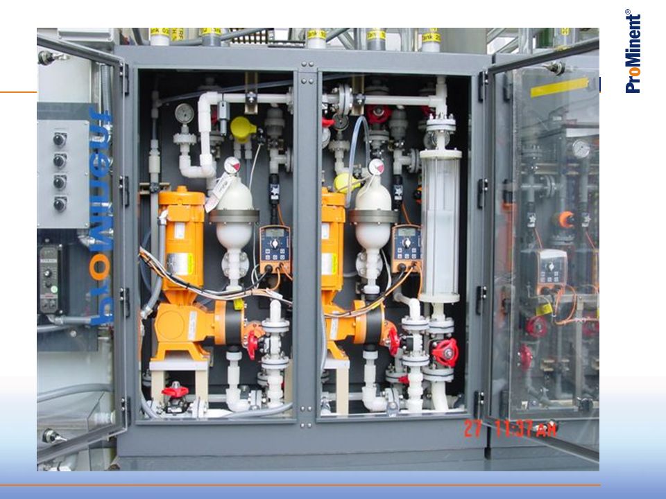
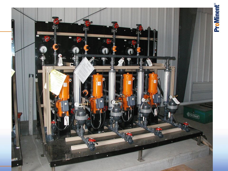
Packaged Systems Engineered solution: Pumps Controllers Accessories Engineered in-house Assembled in-house

36
ProMix-S Polymer Feed System
High efficiency mixing chamber 3 distinct mixing zones – consistent tapered mixing energy Unique injection check valve with easy access Can be used online or as make-down system Precise delivery of activated polymer solution

37
Standardized designs on panels Custom panels
Panel Shop UL 508, UL 698A, NFPA 70 (NEC), & NFPA 79 Standardized designs on panels Custom panels
, & NFPA 79. Standardized designs on panels. Custom panels.")
38
Specialty Products - ProMaqua
Chlorine Dioxide Generators Ozone Generators UV Disinfection Reverse Osmosis Polymer Systems (Tomal)
")
39
Specialty Products - ProMaqua
BelloZon Chlorine Dioxide Generation LegioZon BonoZon Ozone Generation Dulcodes UV Disinfection Reverse Osmosis Electrolysis

40
Tomal PolyRex Versatile system for batchwise preparation of polymer solutions. Powder or Liquids

41
Tomal metering equipment for 3 different chemicals.

42
End of Specialty Products
Any questions??

43
New PFC Products

44
Finally approved for PVDF Concept Beta Gala Delta Sigma ProMus
NSF 61 Certification Finally approved for PVDF Concept Beta Gala Delta Sigma ProMus Hypo, sulfuric, caustic, silicic acid, alum, ferric, bisulfite Plans are to label pumps Postcard ready

45
New Beta/b Pump New Complete redesign of the pump New electronics New design New functions Similar to Beta/a Same capacity ratings Same pump models Available January 2010?

46
New external contact External contact input with Pulse Control as standard Range 1:64 – 64:1 Adapted for water meters, etc. Optimal efficiency of the pump No additional devices required

47
Capacities Pump type Stroke frequency Capacity Backpressure (spm)
(gph) (psi) BT4b 1000 180 0.20 145 BT4b 1601 0.29 232 BT4b 1602 0.58 BT4b 1604 1.00 BT4b 0708 1.88 102 BT4b 0413 3.25 58 BT4b 0220 5.02 29 BT5b 2504 0.77 363 BT5b 1008 1.80 BT5b 0713 2.91 BT5b 0420 4.52 BT5b 0232 8.45
 (psi) BT4b BT4b BT4b BT4b BT4b BT4b BT4b BT5b BT5b BT5b BT5b BT5b")
48
Safety diaphragm for Sigma Series
Diaphragm rupture monitoring system using a multi-layer diaphragm. Upon rupture, chemical is contained between layers and channeled to sensor area. The switch is activated for a visual indication of rupture or generate an alarm/stop pump. Visual indication is for both Basic and Control versions Basic version can have dry contact option Control version has pump stop and alarm. 2

49
Safety diaphragm Sigma
S Multilayer safety diaphragm, with optical rupture indicator (Standard) A Multilayer safety diaphragm, with rupture indicator, electrical, „pump stopping function B Multilayer safety diaphragm, with rupture indicator, electrical, „pump alarm function 49
 A Multilayer safety diaphragm, with rupture indicator, electrical, „pump stopping function. B Multilayer safety diaphragm, with rupture indicator, electrical, „pump alarm function. 49.")
50
Multilayer Safety Diaphragm
Sensor area Diaphragm rupture EPDM + Polyester layer PTFE Operation layer Gap Metallic core PTFE Safety layer J. Gede

51
Multilayer Safety Diaphragm
Operating status, diaphragm is o.k. A diaphragm rupture causes a rise of pressure in the sensor area which triggers the diaphragm rupture sensor. J. Gede

52
Safety Diaphragm for Sigma Series
Sigma 1 available by 1/1/10 Sigma 2 available now? Sigma 3 available in January Cross compatibility Possible to put Old liquid ends on New drive units Not possible to put New liquid ends on Old drive unit Word from PMHD is that all Safety Diaphragms will be available in 2010 3 52

53
Free Chlorine Sensor CLO 1 and CLO 2
CLO 1 for high pressures up to 116 psi Amperometric sensor without membrane No pH Compensation needed – up to pH 9 Measures HOCl and OCl 2 and 10 ppm sensors ( , ) CLO 2 for disinfection with open electrolysis Not suitable for dirty water High temps up to 158F 2 ppm only ( )
 CLO 2 for disinfection with open electrolysis. Not suitable for dirty water. High temps up to 158F. 2 ppm only ( )")
54
Sensor CLO 1 and 2-mA - Technical Data
Measuring ranges: 0-2 and 0-10ppm pH-range: 1 – 10 Operating temperature: 41 – 113°F Max. pressure: 116 psi Response time t90: 30 s Sample flow: 8 – 160 gph Voltage supply: 16 – 24 VDC Output signal: 4 – 20 mA/ temperature compensated, not calibrated Shaft material: PVC/ PVDF Membrane cap material: PVDF Membrane material: Silicone Protection Class: IP 65

55
New Features of Chlorine Dioxide Sensor Type CDR 1
Resistance against pollutants by hydrophobic silicone membrane Reduced clogging from solid particles/dirt Reduced interference by chemicals which are dissolved in water Operating temperature up to 140°F by suitable sensor materials Available now p/n CDR 1-mA-0.5 ppm ppm CDR 1-mA-2 ppm ppm CDR 1-mA-10 ppm ppm

56
Sensor CDR 1-mA - Technical Data
Measuring ranges: CDR 1-mA ppm CDR 1-mA ppm CDR 1-mA ppm pH-range: 1 – 10 Operating temperature: 1 – 131°F (short term 140°F) Max. pressure: 44 psi Response time t90: 2 – 3 min Sample flow: gph Voltage supply: 16 – 24 VDC Output signal: 4 – 20 mA temperature compensated, not calibrated Shaft material: PVC-C Membrane cap material: PVDF Membrane material: Silicone Protection Class: IP 65 Compatible controller: D1CA, B, D2C Compatible housings ; DGMA und DLG III 223 mm 25 mm
 Max. pressure: 44 psi. Response time t90: 2 – 3 min. Sample flow: 8-16 gph. Voltage supply: 16 – 24 VDC. Output signal: 4 – 20 mA temperature compensated, not calibrated. Shaft material: PVC-C. Membrane cap material: PVDF. Membrane material: Silicone. Protection Class: IP 65. Compatible controller: D1CA, B, D2C. Compatible housings ; DGMA und DLG III. 223 mm. 25 mm")
57
Newly Released Products from PMHD
Free Chlorine Sensor CLE 3-mA 0-5 ppm p/n Not in PFC catalog On order from PMHD Free Chlorine Sensor CLE 3.1-mA p/n Currently in PFC catalog In stock

58
Metering Pump Hydraulics

59
What is a Metering Pump? Hydraulic Institute Definition:
“A controlled volume pump (also called a “metering”, “proportioning” or “chemical injection pump”) is a reciprocating power pump used to accurately displace a predetermined volume of liquid in a specified time period and is driven by power from an outside source applied to the pump mechanism. It includes a mechanism for varying the effective plunger, piston or diaphragm displacement.” Some Pump Manufacturers Add: “It includes a mechanism for varying the effective frequency of displacements.”
 is a reciprocating power pump used to accurately displace a predetermined volume of liquid in a specified time period and is driven by power from an outside source applied to the pump mechanism. It includes a mechanism for varying the effective plunger, piston or diaphragm displacement. Some Pump Manufacturers Add: It includes a mechanism for varying the effective frequency of displacements.")
60
Reciprocating Diaphragm Metering Pump Stroke Cycle
Suction Stroke Begins: discharge valve closes, suction valve opens, chamber fills. Suction Stroke Complete. Fluid chamber is full. Discharge Stroke Begins: discharge valve opens, suction valve closes Discharge Stroke Complete. Fluid in chamber is displaced.

61
Control of Reciprocating Metering Pump Output
H O A Variable Speed Drive adjusts frequency of strokes. % Speed Stroke length knob (or stroke positioning motor) adjusts displacement per stroke.
 adjusts displacement per stroke.")
62
Metering Pump Output Adjustments
Variable Frequency Capacity per stroke known by calibration Total output can be calculated easily (capacity/stroke X freq.) Total output linear with frequency (50% freq. = 50% output) May require pulsation dampener or static mixer to prevent slugs at low frequency
 Total output linear with frequency (50% freq. = 50% output) May require pulsation dampener or static mixer to prevent slugs at low frequency.")
63
Metering Pump Output Adjustments
Variable Stroke Length Capacity per stroke unknown, calibrate at constant frequency Total output not linear with stroke length e.g. upper and lower limits may not be linear Output therefore not linear with analog control signal Repeatability poor below 20% stroke length Ensures constant chemical addition - no delay

64
Turndown Ratio Ratio of maximum output to minimum output within rated repeatability specifications (e.g. max output = 100%, min. repeatable output = 10%, turndown ratio = 10:1). H O A Variable Speed Drive Turndown Ratio: 10:1 % Speed Multiplied by: Stroke Length Positioner Turndown Ratio: 10:1 Total Turndown Ratio: 100:1
. H O A. Variable Speed Drive Turndown Ratio: 10:1. % Speed. Multiplied by: Stroke Length Positioner Turndown Ratio: 10:1. Total Turndown Ratio: 100:1.")
65
Metering Pump Liquid Ends
Hydraulic Diaphragm Liquid End Mechanical Diaphragm Liquid End Packed Plunger Liquid End

66
Mechanically-Actuated Diaphragm Liquid End
Reciprocating Shaft Advantages: - Lower cost due to simpler construction - Ease of diaphragm replacement Sealless design No possibility of cross-contamination of hydraulic fluid and chemical Greater suction lift ( up to 20’) Disadvantages: - Lower pressure ratings (max <200 psig) - Lower repeatability (< +/- 2%) Diaphragm with Steel Core
 Disadvantages: - Lower pressure ratings (max <200 psig) - Lower repeatability (< +/- 2%) Diaphragm with Steel Core.")
67
Liquid End Cutaway View
Liquid End Features: • Short Stroke Length • Concave/Convex Design • Reduces “dead volume” • Increases suction lift • Eliminates bubbles • Self priming

68
Hydraulically-Driven Diaphragm Liquid End
Air Bleed / Pressure Relief Valve Advantages: - Higher pressure capabilities - Sealless design - Greater repeatability (< +/- 1%) Disadvantages: - Possibility of cross-contamination of hydraulic fluid and chemical - Higher cost due to complexity of design Difficulty of diaphragm replacement and balancing of hydraulic fluid Low suction lift (about 4’) Piston Make-Up Valve Hydraulic Fluid Reservoir Valve Actuator Diaphragm
 Disadvantages: - Possibility of cross-contamination of hydraulic fluid and chemical. - Higher cost due to complexity of design. Difficulty of diaphragm replacement and balancing of hydraulic fluid. Low suction lift (about 4’) Piston. Make-Up Valve. Hydraulic Fluid Reservoir. Valve Actuator. Diaphragm.")
69
Packed Plunger Liquid End
Flush Connector Plunger Advantages: - High pressure capabilities (4600 psig) - Greater repeatability (< +/- 0.5%) Disadvantages: - Fugitive emissions may escape through packing Packing
 - Greater repeatability (< +/- 0.5%) Disadvantages: - Fugitive emissions may escape through packing. Packing.")
70
What’s all this?

71
Metering Pump System Hydraulics and Application of Accessories
The metering pump system design, the fluid pumped, and the accessories installed all play a vital role in system safety, repeatability and reliability. Key Concept: Metering Pump System

72
Best Practices

73
Suction Head Negative Suction Head (suction lift)
Positive Suction Head (flooded suction)
")
74
Suction Lift Atmospheric pressure always pushes down on any fluid surface. When the pump diaphragm creates a negative pressure in the pump head, atmospheric pressure forces fluid up the suction tube to fill the cavity. Atmospheric pressure at 500 feet above sea level = 14.5 psia = 1 bar = 34 feet of water If the pump pulled a perfect vacuum, the maximum suction lift possible on earth, pumping water, is 34 feet. 14.5 psia

75
Suction Lift What happens if the tank is not vented (open to atmosphere)? 14.5 psia 14.5 psia 14.5 psia

76
Specific Gravity Specific Gravity is the fluid’s density in relation to the density of water (S.G. 1.0). For example: Sulfuric acid density = lbs/gal Therefore: Water density = lbs/gal S.G. = 1.84 Ammonia density = lbs/gal Therefore Water density = lbs/gal S.G. = 0.63 Because atmospheric pressure forces fluid into the pump head during the suction stroke, if the fluid has a specific gravity greater than 1.0, the suction lift ability will be reduced. Specific gravity is independent of viscosity, and does not impact pump capacity, only suction lift capability.

77
Specific Gravity Impact on Suction Lift
Actual Suction Lift = Rated Suction Lift (water) / S.G. Rated Suction Lift for VAMb04120 = 6.6 feet Application: Chromic Acid (1.4 SG) Actual Suction Lift = 6.6 / 1.4 = 4.7’
 / S.G. Rated Suction Lift for VAMb04120 = 6.6 feet. Application: Chromic Acid (1.4 SG) Actual Suction Lift = 6.6 / 1.4 = 4.7’")
78
Viscosity Viscosity is a measure of a fluid’s resistance to flow.
Viscosities greater than that of water increase friction loss and result in reduced pump capacity. When selecting a pump for viscous fluids: Oversize the pump Put springs in the valves to help seat the balls Use high viscosity solenoid pumps Reduce stroking rate to minimum possible Keep stroke length as great as possible Provide flooded suction with oversized suction line

79
Vapor Pressure Matter exist as solids, liquids or gasses. The state of matter depends on the compound itself, the pressure around it, and the temperature. The Vapor Pressure of any fluid relates to the pressure and temperature at which it flashes from a liquid phase to a gas phase. It is defined as the pressure exerted when a liquid is in equilibrium with its own vapor. The higher the vapor pressure, the more likely the fluid will vaporize on the suction side of a pump during the suction stroke, causing cavitation.

80
Chemical Metering System Accessories
REMEMBER: A metering pump alone does not provide safe, repeatable and reliable chemical metering! Only a complete metering system, including the metering pump and accessories, can provide safety, repeatability, and long term reliability of the pump system. Benefits provided by the accessories... Accessory Safety Repeatability Reliability Foot valve Keeps prime Prevents cavitation Backpressure Valve Provides pressure Anti-Siphon Valve Prevents siphoning Pressure Relief Valve Prevents bursting Prevents overpressure Pulsation Dampener Minimizes slugs Prevents pressure surge Pressure Gauge Prevents overpressure Show actual pressure Injection Valve Prevents backflow Provides pressure

81
Prevents over-pressurizing pump and piping system.
Pressure Relief Valve Prevents over-pressurizing pump and piping system. “A safety device” Note: The internal pressure relief valve does not protect the system Pressure Adjusting Nut Diaphragm Spring Diaphragm Hub

82
Pressure Relief Options - Flooded Suction
Pressure Relief may discharge back to tank, but where tank is distant from pump, relief back to suction line is common. 3-port PRV 2-Port BPV on Tee

83
Pressure Relief Options - Suction Lift
Two port back-pressure valve off of a tee on the discharge line Three port in-line pressure relief valve discharges to tank through relief port

84
Provides backpressure to improve repeatability.
Backpressure Valve Provides backpressure to improve repeatability. Prevents siphoning when suction head exceeds discharge head. Pressure Adjusting Nut Spring Diaphragm Diaphragm Hub

85
Backpressure Valve The injection quill can create a venturi effect in a flowing pipe, developing a vacuum. This can draw chemical through the system even if the pump is stopped. The anti-siphon (backpressure) valve prevents the vacuum from causing chemical to be drawn into water line.
 valve prevents the vacuum from causing chemical to be drawn into water line.")
86
Backpressure Valve The backpressure valve also prevents fluid from simply free-flowing through the system when the suction port is higher than the point of discharge.

87
Backpressure Valve When discharging into a vacuum line, use two backpressure valves to ensure maximum protection against siphoning. Regulatory agencies may require use of two anti-siphon valves in certain applications such as adding fluoride to drinking water. The backpressure created by the two valves (and the injection valve) is not additive. Whichever valve is set at the highest pressure will determine the system pressure at the pump.
 is not additive. Whichever valve is set at the highest pressure will determine the system pressure at the pump.")
88
Multifunction Valve An inexpensive device combining both a pressure relief and backpressure valve. Mounted directly on the liquid end of the pump. Multifunction: backpressure, antisiphon, pressure relief, priming and draining the discharge line

89
Pulsation Dampener In a reciprocating pump system, the entire fluid column between the pump and injection point stops flowing at each suction stroke and is forced to flow at each discharge stroke. Overcoming inertia creates large momentary pressure spikes on the pump system.

90
Pulsation Dampener AIR FLUID A pulsation dampener minimizes the pressure spikes by using compressed air to absorb the forces due to momentum of the fluid inertia. The flow losses are called acceleration/deceleration forces.

91
Pulsation Dampener Principle of Operation: Air is compressible, fluid is not. Size dampener volume to 26 times fluid displacement per stroke, or consult piping program. Charge dampener air pressure to 90% of fluid pressure. You must have backpressure for dampener to be effective. Locate dampener as close to pump as possible, preferably as shown.

92
Foot Valve The foot valve is used in a suction lift application to prevent loss of prime when the pump is stopped, and to improve repeatability by preventing cavitation. Suction Tube Tube Fitting Check Ball Ball Check Seat 30 mesh screen keeps solids out Ceramic weight keeps suction line straight, ports let fluid in.

93
Injection Valve Injection quill puts chemical into flow for good mixing NPT thread to mount into pipe Valve Spring provides backpressure, ensures ball seating. Check Ball Ball Check Seat Tube Fitting Discharge Tubing from Pump

94
Calibration Column Provide a verification of the flow rate of the chemical feed pump Place on suction side Size for minimum 30 sec. Marked in gallons or milliliters

95
Typical Accessory Installation (Suction Lift)
Injection Valve prevents backflow from pipe Backpressure/Antisiphon valve provides backpressure for repeatability, prevents siphoning Pressure gauge allows setting valve pressures Pulsation dampener reduces head loss, pulsation Pressure relief valve protects system components Foot valve/strainer prevents loss of prime, plugging by solids

96
Thank you for your attention Any Questions? 15 Minute Break

97
Pump Identcodes and Functions
Gamma/L (GALa) Options
 Options.")
98
First selection Default Tells us this is the Gamma/L, version ‘a’
Gamma/L is often referred to as “GALA”

99
“Pump Version” “Size” of the liquid end
Pressure and volume capabilities Note: first 2 digits refer to the pressure in BAR (1 BAR = 14.5 psi) Final digits are approximate volume in Liters per hour Clues to solenoid size = what liquid ends can be changed for this drive We can calculate Volume per stroke (shown in chart) Required to size Pulse dampener
 Final digits are approximate volume in Liters per hour. Clues to solenoid size = what liquid ends can be changed for this drive. We can calculate Volume per stroke (shown in chart) Required to size Pulse dampener.")
100
Liquid end: Materials, Seal, Version
These 3 selections define the Liquid End Critical to follow notes in parentheses after options These selections are determined using the chemical resistance information from the “General Information” section of the catalog If you cannot find information on a chemical and the customer cannot determine what to use, ask someone who knows!

101
Connection What size tubing we intend to use with the pump
Refer to the technical data in chart above for typical tubing size for Liquid End 1000,1601,1602 can use ‘0’ (‘6’ on request) selection here, others should be ‘6’ unless previous digit (from previous slide) is a ‘4’ then you would also use a ‘0’ Where we show:1/4 x 3/16 or ½ x 3/8, the first is the outside dimension of the tubing (must be larger) and the second is the inside diameter of the tubing We can offer connector set to use “3/8” tubing (3/8 x ¼) Enter as a separate line item 1 connection per valve (remember foot and injection valves when you count these) Connector set to include 2 is part number: (PVT) It is important to know this because this is a common tubing size for our competitors and it helps us displace their products.
 selection here, others should be ‘6’ unless previous digit (from previous slide) is a ‘4’ then you would also use a ‘0’ Where we show:1/4 x 3/16 or ½ x 3/8, the first is the outside dimension of the tubing (must be larger) and the second is the inside diameter of the tubing. We can offer connector set to use 3/8 tubing (3/8 x ¼) Enter as a separate line item. 1 connection per valve (remember foot and injection valves when you count these) Connector set to include 2 is part number: (PVT) It is important to know this because this is a common tubing size for our competitors and it helps us displace their products.")
102
Labeling This is a default ‘0’ selection
The only time you might see this change is if an OEM requests their label be placed on the pump and they commit to a quantity order.

103
Electrical Connection
Determined by what the customer is supplying to the pump. ‘M’ or ‘N’ might be selected if the customer is getting power from a battery or possibly a solar source (be sure to follow notes in parentheses). Most common is ‘U’ Some early versions of Gamma/L used separate codes for 115 and 230 volt pumps. We would now cross these over to ‘U’.
. Most common is ‘U’ Some early versions of Gamma/L used separate codes for 115 and 230 volt pumps. We would now cross these over to ‘U’.")
104
Power cable Determined by what the user plans to power the pump with.
If previous selection is ‘U’, 115 or 230 can be used to power the pump by changing the cord or cutting off the plug and hard wiring As noted above the standard cord is 6 feet Longer power cords can be ordered as a separate line item with a note to install in pump 15 foot 115 volt is pn: 30 foot 115 volt is pn:

105
Relay = Output from pump (slide 1)
‘1’ and ‘3’ use the same board in the pump Each uses 3 wires (c) common, (NC) normally closed, (NO) normally open. With these 3 wires you get “both changes of state” with either relay option. ‘1’ energizes the board on power-up and maintains power to board until fault, then it “turns board off.” ‘3’ only “turns board on” when fault occurs Since ‘1’ is energized as soon as pump is powered up, this option will change states if fuse inside pump blows or if pump is unplugged. Because ‘1’ can “monitor power,” recommend this over the ‘3’
 common, (NC) normally closed, (NO) normally open. With these 3 wires you get both changes of state with either relay option. ‘1’ energizes the board on power-up and maintains power to board until fault, then it turns board off. ‘3’ only turns board on when fault occurs. Since ‘1’ is energized as soon as pump is powered up, this option will change states if fuse inside pump blows or if pump is unplugged. Because ‘1’ can monitor power, recommend this over the ‘3’")
106
Relay = Output from pump (slide 2)
These options combine options ‘1’ and ‘3’ with a pacing relay A pacing relay gives 1 contact closure with each stroke of the pump The pacing relay can be used as a contact input to a second pump among other uses. With these 2 options you have the same board but now use 4 wires out from the pump Option ‘4’ has 2 wires “closed” until fault and 2 that “pace” or close with each stroke Option ‘5’ has 2 wires “open” until fault and 2 that “pace” or close with each stroke To determine which of these to use you need to know what signal the device you are sending to is looking for. If pump has no relay option you can add ‘1’ or ‘4’ in the field Kit to add ‘1’ PN: Kit to add ‘4’ PN:

107
Relay = Output from pump (slide 3)
These 3 options combine options from the previous 2 slides with an mA output. These use 4 wires out 2 for whichever relay you choose and the other 2 for the mA signal. The mA signal is a product of both Stroke Length and Stroke Frequency as shown in the formula to the above right.

108
Accessories These accessories include the foot and injection valves.
Follow notes to the right of the option for which pump gets the accessories. SS, TT, and High viscosity liquid ends do not get these

109
Control Variants (inputs to the pump)
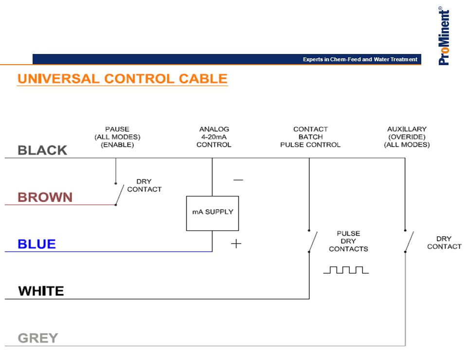
These options are how we control the frequency or stroke rate of the pump. External is a pulsing contact: 1 input strokes the pump 1 time ‘Pulse Control’ allows us to change the ratio from 1:1 to what we need it to be (may be 1 in strokes the pump…5 times or 5 inputs stroke the pump 1 time) Analog is a 4 to 20 mA signal. 4 mA the pump stops and 20 mA the pump runs at max frequency; 180 strokes per minute (we can change this response unless ‘C’, ‘D’, or ‘E’ were chosen for the relay output). ‘P’ is special it is both input and output Remember a universal control cable to get the control signal into the pump – 6 feet – 15 feet – 30 feet
 Analog is a 4 to 20 mA signal. 4 mA the pump stops and 20 mA the pump runs at max frequency; 180 strokes per minute (we can change this response unless ‘C’, ‘D’, or ‘E’ were chosen for the relay output). ‘P’ is special it is both input and output. Remember a universal control cable to get the control signal into the pump – 6 feet – 15 feet – 30 feet.")
110
Access code Adds a level of security to protect the settings of the pump 2 codes give different levels of access Cannot lock-out the stroke length No cost adder for this option, so always include this if left up to you. If they don’t want to use it, they don’t have to set it. 1234 is the override code for this option if users number is lost

111
Last 2 options Always select ‘0’ for these last 2 items

113
End of Metering Pump Session
Frei/Sanns

114
D1C Controller/Analyzer

115
D1C Identcode

116
D1C Identcode

117
D1C Identcode

118
D1C Identcode

119
D1C Identcode

120
D1C Wiring

121
D2C Wiring

122
Cooling Water, Boiler Water, Wash Water, Gas Scrubbing
Industrial Chemical Metering and Control Applications Utilities Cooling Water, Boiler Water, Wash Water, Gas Scrubbing Outgoing Wastewater Industrial Plant Incoming Water pH Control, Clarification, Filtration, Chlorination, Dechlorination Filtration, Chlorination, RO/DI Process Container Disinfection, Container Filling, CIP, Wet Process Chemistry, Product Ingredient Metering (color, flavor, fragrance), Metal Finishing ProMinent Fluid Controls
, Metal Finishing. ProMinent Fluid Controls.")
123
Pre-Engineered Systems
Frei/Sanns

124
Typical Potable Water Treatment Chemical Feed and Process Control
PreOxidation Flocculation Filtration Softening Cl2 cond Potassium Permanganate, Chlorine Dioxide, Ozone Polymer, Alum Lime Ammonia (pre-or post) pH Adjust/ Corrosion Inhibition Fluoridation Chlorination pH Cl2 Hydrofluosilicic Acid Caustic Phosphate Sodium Hypochlorite Sodium Hypochlorite Cl2 Water Distribution System Rechlorination ProMinent Fluid Controls
 pH Adjust/ Corrosion. Inhibition. Fluoridation. Chlorination. pH. Cl2. Hydrofluosilicic Acid. Caustic Phosphate. Sodium Hypochlorite. Sodium Hypochlorite. Cl2. Water Distribution System. Rechlorination. ProMinent Fluid Controls.")
125
(1) Dechlorinate for TFC (polyamide) membranes
Typical Reverse Osmosis Chemical Feed and Process Control RO Membranes Pre- Filtration Chlorinate (1) Dechlorinate (2) pH Adjust ORP pH Sodium Hypo Sodium Bisulfite Acid cond Concentrate Antiscalant CIP Loop (1) Dechlorinate for TFC (polyamide) membranes (2) pH adjust for Cellulose Acetate membranes to pH 5.5 to 6.5 Membrane Cleaner cond Permeate ProMinent Fluid Controls
 Dechlorinate. (2) pH Adjust. ORP. pH. Sodium Hypo. Sodium Bisulfite. Acid. cond. Concentrate. Antiscalant. CIP Loop. (1) Dechlorinate for TFC (polyamide) membranes. (2) pH adjust for Cellulose Acetate membranes to pH 5.5 to 6.5. Membrane Cleaner. cond. Permeate. ProMinent Fluid Controls.")
126
PLC Product Ingredients ProMinent Fluid Controls
Batch Ingredient Metering and Container Filling PLC Product Ingredients ProMinent Fluid Controls

127
FM cond Scale Inhibitor Corrosion Inhibitor Heat Exchanger ORP
Typical Cooling Water Chemical Feed and Process Control Level Controlled Makeup FM cond Scale Inhibitor Corrosion Inhibitor Heat Exchanger ORP Sodium Hypo ProMinent Fluid Controls

128
Sulfite or Oxygen Scavenger Alkalinity Booster & Polymer
Typical Boiler Water Chemical Feed and Process Control Deaerator / Feedwater Storage FM Boiler Sulfite or Oxygen Scavenger Alkalinity Booster & Polymer Phosphate Amines cond Scale Inhibitor Steam Use Site Condensate ProMinent Fluid Controls

129
Typical Wastewater Treatment Chemical Feed and Process Control
Flow Equalization, Sedimentation Aeration Clarification RAS Defoamer Polymer, Ferric Chloride Sodium Hypo Sludge Digestion Odor Control ORP pH Dechlorination Chlorination Sludge Dewatering Caustic ORP Cl2 Polymer Sodium Hypochlorite Sodium Bisulfite ProMinent Fluid Controls

130
Typical Odor Control Scrubber Chemical Feed and Process Control
Sodium Hypo Sodium Hydroxide ORP pH Odorous Air ProMinent Fluid Controls

131
Selling Metering Pumps

132
Do your Homework What is the application? Will a ProMinent Pump Work? What are they pumping? Material Compatibility Check Check Flow Rates Check System Pressures What Pump Options do they need? Indoor or Outdoor application? Make sure that the application will not fail!!! DON’T JUST TAKE AN ORDER

133
Selling Strategies Consult your Regional or CSD contact Know who your competition is and what they offer ProMinent has a library of competition – use it Use other product lines to get in the door Survey the Scene Ask questions about other applications in the plant or process Leave pricing for last Discuss Benefits – not just Features Have a pump to Demo Make sure that the customer is comparing “Apples to Apples” Speak of the Great service and support from you and PFC We inventory all parts……Do you stock anything? Every pump is tested before it leaves the factory

134
Selling Strategies Attend PFC training classes so that you are thoroughly trained Spend time with your Regional learning product and applications Really try to understand your customer’s application Have some similar references prepared Make sure that you have UPDATED LITERATURE!!!!!!! Know up front that ProMinent is not the cheapest product Try Selling Up!!!! Ask questions & take notes Follow up with your customer ASAP If you promise something – DO IT!!! If you cannot get a pump sale, try and sell an analyzer

135
Top 5 Selling Tips

136
Top 5 Selling Tips Identify Target Accounts Know your TA’s/Customer’s Business Utilize your resources Know the product features and benefits which impact the prospect Follow up

137
Identify Target Accounts
Low hanging fruit Existing customers for other lines Existing relationships Accounts with significant amount of competitive equipment Accounts which fit for multiple lines Fill out TA form

138
Know your TA’s/Customer’s Business
Influential Selling Research on internet Ask colleagues and ProMinent “Do you use pumps?” doesn’t give the customer a reason to be interested How can we bring value to the customer? What are the problems your contact has to deal with? Show that you care

139
Utilize your resources
Associates ProMinent USA ProMinent Heidelberg ProMinent Applications section on internet

140
Know the product features and benefits which impact the prospect
Customers/prospects can purchase equipment off the web Customers/prospects are more knowledgeable than ever before A feature means nothing unless it has value (Benefit) to the prospect Ask why the customer needs you Show them how your products and support will help them solve issues at hand
 to the prospect. Ask why the customer needs you. Show them how your products and support will help them solve issues at hand.")
141
Follow up Everyone is busy Turning quotes to orders requires diligence Follow up is easy by phone or Customers and Prospects will appreciate follow up if it is done professionally Don’t press or back them in a corner. They don’t owe you an order Decisions seem to take longer for $$$ approval. Help them manage up by sending them ROI or other info that is useful to them

142
Metering Pump Opportunities

143
Opportunities & Applications For Pumps
Municipalities Drinking water - Chlorine (sodium hypochlorite) Dechlor (sodium bisulfite) pH control (acid & caustic) H2O2 feed CLO2 Polymer feed and/or makedown Ferric LAS
 Dechlor (sodium bisulfite) pH control (acid & caustic) H2O2 feed. CLO2. Polymer feed and/or makedown. Ferric. LAS.")
144
Opportunities & Applications For Pumps
Food Processing Post harvest disinfection with CLO2/PAA/Chlorine for flume & tank washing and sprayers to destroy dangerous bacteria and microorganisms before packaging (E-Coli / Salmonella) Oil & Gas Process chemical feed Wastewater treatment pH control Cooling towers & boilers Mercaptan feed Metal Surface Finishing
 Oil & Gas. Process chemical feed. Wastewater treatment. pH control. Cooling towers & boilers. Mercaptan feed. Metal Surface Finishing.")
145
Opportunities & Applications For Pumps
Waterparks/Commercial Pools/Spas Hypo Feed/Acid Feed/Bromine Feed Wineries CLO2 for disinfection of tanks/vats/trucks/bottles – chlorine residual free Breweries Cooling towers & boilers CIP & disinfection Wastewater treatment – pH control Poultry & Seafood Disinfection / CIP Cooling/chilling water

146
Opportunities & Applications For Pumps
Aquarium & Zoos Water disinfection control Pharmaceuticals Process water treatment / CIP Hospitals Disinfection of potable water Leigonella prevention Cooling towers & boilers Semiconductor Wastewater treatment Process water

147
Who Do I Contact At The Plant Level?
Food Processing QC manager / maintenance supervisor Oil & Gas Operation / maintenance technicians Metals Surface Finishing Wineries Wine master / QC manager Breweries Brew master / QC manager Poultry & Seafood

148
Who Do I Contact At The Plant Level?
Aquarium & Zoos Operation / maintenance technicians Pharmaceuticals QC manager / maintenance supervisor Hospitals Semiconductor Municipalities Operation / maintenance technicians / instrument techs Waterparks/Commercial Pools/Spas Disinfection Manager Maintenance Supervisor

149
Analyzer Applications

150
Analyzer Applications
Analyzers/Controllers/Monitors are used to measure and regulate the result of a chemical addition in an aqueous solution. Where there’s a pump….there’s a measuring device somewhere downstream!! Sometimes it may be easier to lead with a controller and then sell the pumps.

151
Analyzer Applications
Food (PAA, pH) Beverage (fluoride, pH, chlorine, PAA) Paper (pH, chlorine) Poultry (chlorine, pH) Meat (chlorine, pH) Rendering (chlorine, ClO2, pH) CIP (pH)
 Beverage (fluoride, pH, chlorine, PAA) Paper (pH, chlorine) Poultry (chlorine, pH) Meat (chlorine, pH) Rendering (chlorine, ClO2, pH) CIP (pH)")
152
Analyzer Applications
Legionella (ClO2, chlorite) Cooling towers (pH, chlorine) Boilers (pH, chlorine) Bottling machines (O3) Power plants (pH, chlorine) Swimming pools (pH, chlorine) Carwashes (pH) Airports (pH, chlorine) Hotels (pH, chlorine)
 Cooling towers (pH, chlorine) Boilers (pH, chlorine) Bottling machines (O3) Power plants (pH, chlorine) Swimming pools (pH, chlorine) Carwashes (pH) Airports (pH, chlorine) Hotels (pH, chlorine)")
153
Analyzer Applications
Potable water (pH, chlorine, fluoride) Wastewater (pH, chlorine) Fish hatcheries (pH, chlorine, O3) Nurseries (pH) Chemical plants (pH) Automobile manufacturers (pH) Waterparks (pH, chlorine, O3) Zoos (pH, chlorine, O3) Amusement parks (pH, chlorine, O3) Spas (pH, chlorine, Br)
 Wastewater (pH, chlorine) Fish hatcheries (pH, chlorine, O3) Nurseries (pH) Chemical plants (pH) Automobile manufacturers (pH) Waterparks (pH, chlorine, O3) Zoos (pH, chlorine, O3) Amusement parks (pH, chlorine, O3) Spas (pH, chlorine, Br)")
Similar presentations
>")
 Basic design criteria –Phase –Flow Pressure –Temperature Example: 2” Schedule 80.>")


