Download presentation
Presentation is loading. Please wait.

2
Objectives Finish analysis of most common HVAC Systems Cooling Systems Describe vapor compression cycle basics Draw cycle on T-s diagrams Compare real cycles to ideal cycles

5
VAV Dedicated Outdoor Air System (DOAS) with occupancy sensors 100%OA »Exhaust Fan coil units for heating and cooling For ventilation and humidity control VAV box CO 2
 with occupancy sensors 100%OA »Exhaust Fan coil units for heating and cooling For ventilation and humidity control VAV box CO 2")
6
Fan Terminal Units Same as fan coil Can be with or without recirculation

7
HVAC Systems Single zone Multi zone VAVCAV VAVCAV All Hydroinic that relay on infiltration With and without reheaters DOAS with fan coils With reheaters Dual duct Dual duct DOAS with fan coils With and without humidity control This is not the complete list !

8
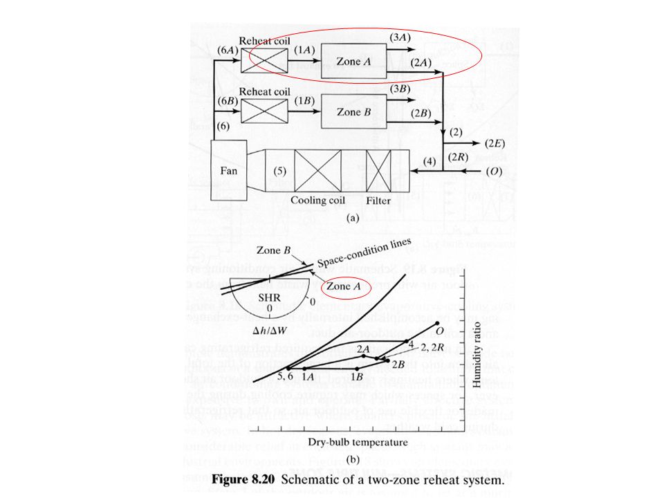
One more examples from your book

9
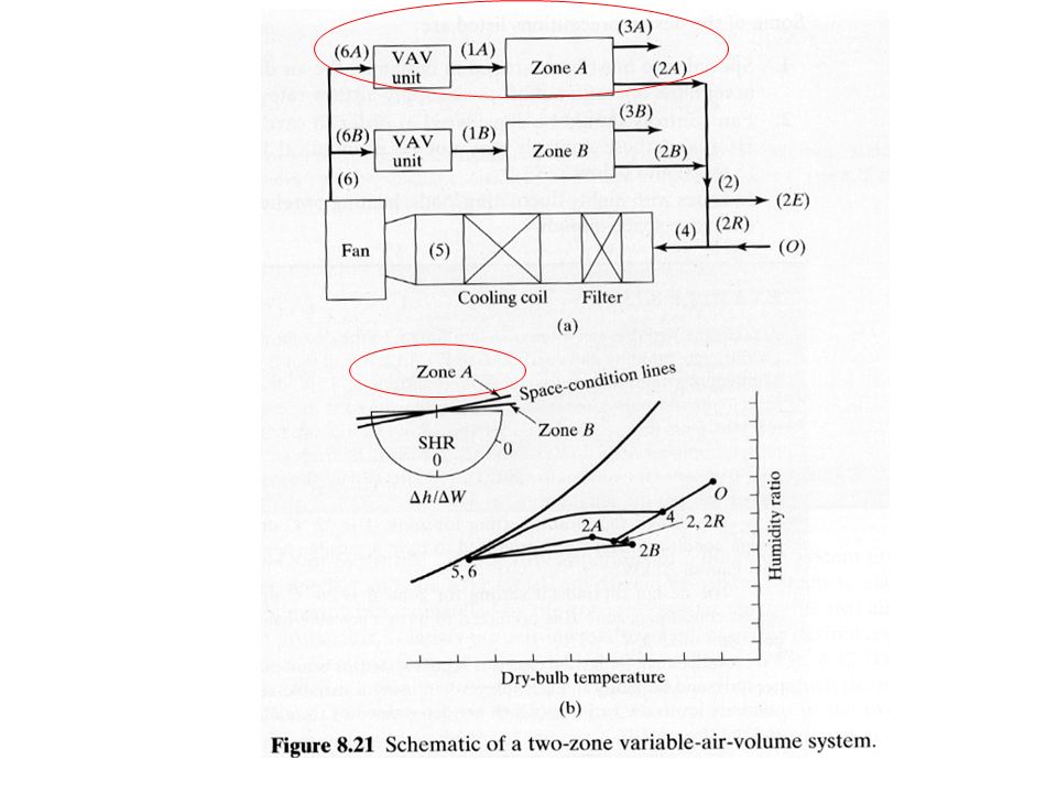
Summary of HVAC Systems Show HVAC processes on a Psychrometric chart Define SA point Think about processes and different ways to get to SA point Analyze HVAC processes for real buildings Single zone Multiple zone

10
Cooling towes Similarity and difference between Evaporative coolers and Cooing towers

11
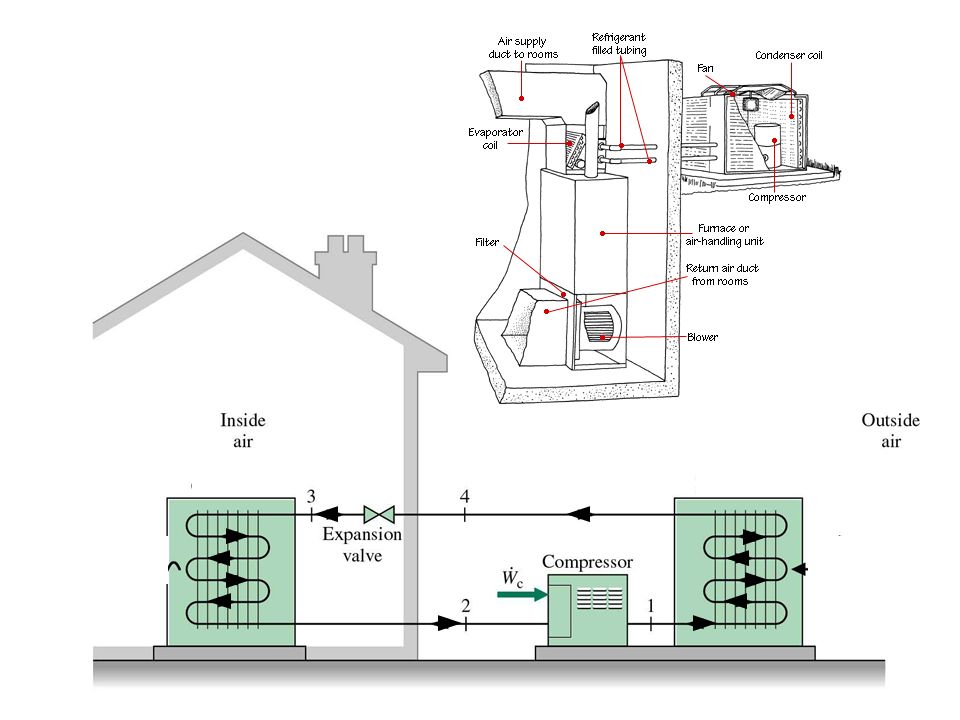
Vapor Compression Cycle Expansion Valve

13
Efficiency First Law Coefficient of performance, COP COP = useful refrigerating effect/net energy supplied COP = q r /w net Second law Refrigerating efficiency, η R η R = COP/COP rev Comparison to ideal reversible cycle

14
Carnot Cycle No cycle can have a higher COP All reversible cycles operating at the same temperatures (T 0, T R ) will have the same COP For constant temp processes dq = Tds COP = T R /(T 0 – T R )
 will have the same COP For constant temp processes dq = Tds COP = T R /(T 0 – T R )")
15
Get Real Assume no heat transfer or potential or kinetic energy transfer in expansion valve COP = (h 3 -h 2 )/(h 4 -h 3 ) Compressor displacement = mv 3
/(h 4 -h 3 ) Compressor displacement = mv 3")
16
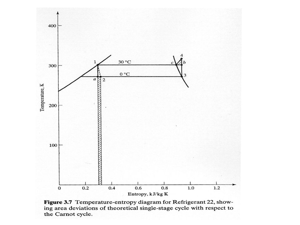
Example R-22 condensing temp of 30 °C (86F) and evaporating temp of 0°C (32 F) Determine a) q carnot w carnot b) Diminished q R and excess w for real cycle caused by throttling and superheat horn c) η R
 and evaporating temp of 0°C (32 F) Determine a) q carnot w carnot b) Diminished q R and excess w for real cycle caused by throttling and superheat horn c) η R")
18
Comparison Between Single-Stage and Carnot Cycles Figure 3.6

19
Subcooling and Superheating Refrigerant may be subcooled in condenser or in liquid line Temperature goes below saturation temperature Refrigerant may be superheated in evaporator or in vapor (suction) line Temperature goes above saturation temperature
 line Temperature goes above saturation temperature")
20
»Two stage systems

21
Multistage Compression Cycles Combine multiple cycles to improve efficiency Prevents excessive compressor discharge temperature Allows low evaporating temperatures (cryogenics)
")
Similar presentations