Download presentation
Presentation is loading. Please wait.

1
Simulation of Non-Solenoidal Current Rampup in NSTX C. E. Kessel and NSTX Team Princeton Plasma Physics Laboratory APS-DPP Annual Meeting, Savannah, Georgia, 11/15-19/2004 Supported by

2
Non-Solenoidal Startup and Current Rampup are Required for Future ST’s Elimination of the solenoid allows the ST to have compact geometry Both Coaxial Helicity Injection (CHI) and PF Coil startup are being pursued on NSTX The plasma current rampup is being examined with High Harmonic Fast Wave (HHFW) for low I P, and NBI for higher I P
 and PF Coil startup are being pursued on NSTX The plasma current rampup is being examined with High Harmonic Fast Wave (HHFW) for low I P, and NBI for higher I P")
3
Non-solenoidal Rampup with HHFW is a Critical Goal for NSTX

4
Simulations of the Plasma Current Rampup Free-boundary Tokamak Simulation Code (TSC) for time-dependent evolution CURRAY for HHFW heating and CD TRANSP for typical NBI characteristics in NSTX
 for time-dependent evolution CURRAY for HHFW heating and CD TRANSP for typical NBI characteristics in NSTX")
5
5 Year Plan Studies Showed that NSTX Can Examine Non-Solenoidal Rampup t = 0. - 0.5 s, HHFW CDt = 0. - 1.5 s, HHFW+NB CD NI I P Overdrive Density ramp to keep T e low

6
To Achieve This in the Experiment is Challenging Plasma must be coupled to HHFW antenna –Plasma must be grown quickly –Plasma-antenna distance must be established and maintained Plasma is at very low current, 50-150 kA Plasma is cold T e < 300 eV, so HHFW waves will not damp efficiently at first (many reflections) Plasma will undergo strong current profile modifications, making shape control difficult
 Plasma will undergo strong current profile modifications, making shape control difficult")
7
Use Simulations to Develop an Approach on the Experiment Use solenoid to ramp I P to a certain level Flattop the OH coil current at its corresponding current Inject 3.0 MW HHFW to heat or heat and drive current, inducing H-mode Progressively lower the I P value where the OH coil is flattoped and HHFW is injected

8
OH Coil is Flattoped at 0.1 s 450 kA Case

10
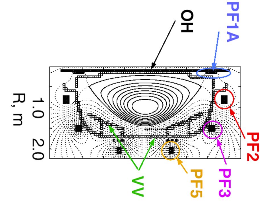
Inject 3.0 MW of HHFW Power at 0.1 s Each PF Coil Links Some Level of Poloidal Flux 450 kA Case

11
CURRAY Ray-Tracing Analysis Determines Heating and Current Deposition 450 kA Case

12
Current Drive Efficiency During the Simulation CD efficiency mostly determined by T(r) and n(r) evolution Small differences for different I P cases 7 /m has the highest CD efficiency Depending on T e assumed at beginning of HHFW injection, absorbed power fraction can vary alot Only 1 reflection allowed
 and n(r) evolution Small differences for different I P cases 7 /m has the highest CD efficiency Depending on T e assumed at beginning of HHFW injection, absorbed power fraction can vary alot Only 1 reflection allowed")
13
Density Prescribed, Temperature from L-mode and H-mode Models L-mode H-mode HHFW Heating

14
3 Cases Using Solenoid to Rampup to 450, 350, and 250 kA

15
On-axis and Minimum Safety Factors Reflect Early Ohmic Heating and Current Diffusion

16
These Plasmas Will Operate Close to the Greenwald Limit and at High P

17
450 kA Case Plasma Currents

18
350 kA Case Plasma Currents

19
250 kA Case Plasma Currents

20
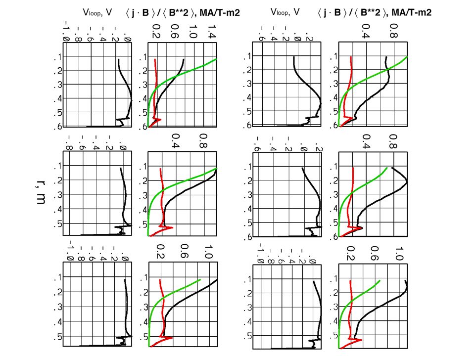
J and V Profile Evolutions Reflect I P vs. I NI

22
No Heating/CD Can Clearly Be Differentiatd From Heating/CD With Flattoped OH

23
Heating Only vs. Heating + CD Heating only increases stored energy, and drives non-inductive bootstrap current (off-axis) Heating only slows ohmic current diffusion and reduces the loop voltage Heating + CD does the above, and drives non- inductive current centered on the axis for HHFW at these temperatures The difference can be hard to see when there is significant ohmic current ----> more pronounced when I NI > I P
 Heating only slows ohmic current diffusion and reduces the loop voltage Heating + CD does the above, and drives non- inductive current centered on the axis for HHFW at these temperatures The difference can be hard to see when there is significant ohmic current ----> more pronounced when I NI > I P.")
24
450 kA Case Plasma Currents and Profiles

25
350 kA Case Plasma Currents and Profiles

26
250 kA Case Plasma Currents and Profiles

27
Ultimately the Low I P Plasmas Must Be Created at Earlier Time Repeat the 3 Cases, but flattop the OH coil and inject HHFW earlier –450 kA at same time as before, t = 0.1 s –350 kA at t = 0.075 s (actually 365 kA) –250 kA at t = 0.04 s (actually 230 kA) Earlier heating changes the safety factor evolution significantly The plasma current values reached are not much different than with the original 3 Cases all with OH flattop and HHFW heat/CD at 0.1 s
 –250 kA at t = 0.04 s (actually 230 kA) Earlier heating changes the safety factor evolution significantly The plasma current values reached are not much different than with the original 3 Cases all with OH flattop and HHFW heat/CD at 0.1 s")
28
3 Cases Using Solenoid to Rampup to 450 kA @ t=0.1s, 350 kA @ t = 0.08 s, 250 kA @ t = 0.04 s

29
Early Heating/CD Has Reversed the Ordering of q(0) Values
 Values")
30
Observations/Conclusions NSTX can examine the critical features of non- solenoidal startup and current rampup Current rampup requires an RF scheme at low I P where NB’s are poorly confined CHI and/or PF Coil startup will deliver a plasma probably at 50-150 kA at an early time This plasma must be coupled to the HHFW antenna for it to heat and drive current NB’s would be added at a higher I P, and would help drive the plasma current higher

31
Observations/Conclusions Simulations are being used to examine approaches to the current rampup –The solenoid can be used to provide the starting plasma for HHFW current rampup –Ip can be ramped to various values at various times to learn how to grow the plasma for antenna coupling and optimize the HHFW heating only or heating and CD –The effect of HHFW heating/CD when the solenoid is flattoped can clearly be observed –Either heating only or heating and CD can drive I P up without the solenoid for starting I P values 250-450 kA, with 3 MW of HHFW power –Injecting HHFW earlier for 250 and 350 kA cases did not result in significantly different final I P values, although the q(0) trajectories were significantly changed
 trajectories were significantly changed")
32
Future Work Add one NB source and include effect on HHFW heating/CD Examine larger HHFW power ----> 6.0 MW Examine evolution of weak to stronger HHFW absorption at low T e Examine lower I p starting points Examine lower B T to get longer pulse lengths, combined with early heating to get safety factor high

Similar presentations


 plasma and disruptions C. Kessel, PPPL ARIES Project Meeting, Jan 23-24, 2012, UCSD.>")


 –All systems operated reliably without any faults Edge Current drive (XP533)>")

