Download presentation
Presentation is loading. Please wait.

1
Interleaving Compounding Packets & Convolution Codes

2
Chunk Interleaving Another way to achieve Forward Error Correction in multimedia is to allow some small chunks to be missing at the receiver. We cannot afford to let all the chunks belonging to the same packet be missing; however, we can afford to let one chunk be missing in each packet. We achieve this through chunk interleaving by producing interleaved code. 10.#

3
Interleaved codes Block parity and Hamming codes are not suited for burst errors because multiple errors cannot be detected by these codes. Interleaving is carried out to spread burst errors into single bit errors which can be detected and corrected by these codes. This technique involves writing m consecutive n-bit code words in m x n matrix and then transmitting the bits column-wise instead of row-wise. Parameter m is called depth of interleaved code.

4
Figure : Interleaving 10.#

5
Example : Construct interleaved code with depth 3 for word “HELLO
Example : Construct interleaved code with depth 3 for word “HELLO !” using even parity Solution @ Even parity at eight bit position Bit Position 8 7 6 5 4 3 2 1 H E L O !

6
Since the depth is three, three rows are transmitted at a time as interleaved code. The transmission sequence starting from LSB will be as under which is final interleaved code

7
Combining Hamming Distance
Hamming distance and interleaving can be combined. We can first create n-bit packets that can correct t-bit errors. Then we interleave m rows and send the bits column by column. In this way, we can automatically correct burst errors up to m × t bits of errors. 10.#

8
Compounding Still another solution is to create a duplicate of each packet with a low-resolution redundancy and combine the redundant version with the next packet. For example, we can create four low-resolution packets out of five high-resolution packets and send them as shown in Figure. 10.#

9
Figure: Compounding high-and-low resolution packets
10.#

10
Convolution codes In block codes in which the check bits are computed for a block of data, convolution codes are generated over a ‘span’ of data bits, e.g. convolution code of constraint length 3 is generated bit by bit using the ‘last 3 data bits’. Each data bit convolved with neighboring bits so that if it gets corrupted during transmission, enough information is carried by the neighboring bits to determine the transmitted bit.

12
O/P Vector of Convolution coder
1 1 [z1 z2] = [xn xn-1 xn-2] 1 0

13
State transition diagram of this encoder is shown in next figure
State transition diagram of this encoder is shown in next figure. Each circle in the diagram represent a state of the encoder, which is the content of two leftmost stages of the shift register. There are four possible states 00,01,10,11. The arrows represent the state transition for the input bit that can be 0 or 1. The label on each arrow shows the input data bit by which the transition is caused and the corresponding output bits.

14
As example, suppose the initial state of the encoder is 00 and the input data sequence is 1011.
The corresponding output sequence of the encoder will be

17
Solution Starting from A at the top left corner in figure and tracing the path through the trellis for the input sequence 0101, we get the output bits as bits as shown in the following table: Output bit sequence : Present State Input bit Next state Output bits A 00 1 C 11 B 01

18
Decoding algorithm (Viterbi algorithm ):
Decoder for the convolution code is based on the maximum likelihood principle. Knowing the encoder behavior and received sequence of bits, we can find the most likely transmitted sequence by analyzing all the possible paths through the trellis. The path which result in the output sequence which is nearest to the received sequence is chosen and the corresponding input bits are the decoded data bits. The decoding algorithm is known as Viterbi algorithm.

20
Step 1. At any point of analysis
Step 1. At any point of analysis. When segment of two paths converge on the same state, we chose one of the paths which is nearer to the received sequence up to that point, for further analysis. Note that a pair of paths converse on each state, e.g. state A can be reached via AAAA or ABCD. But path AAAA result in output sequence which is at a distance of 4 from the first six bits of the received sequence.

21
In the case of the other path ABCD, this distance is only 3
In the case of the other path ABCD, this distance is only 3. Because we are looking for a sequence with the smallest distance, we need not consider the first path for further analysis are ACBA, ACDB, ACBC, and ACDD.

22
Step 2. Having considered the first three pairs of the bits, let us move further. Transitions from the last state arrived at the first step, will result in two potential states depending on the next input bit. Distances of the resulting bit sequence from the received sequence are given in table. Note that we have computed the distances for only selected paths of the first step. The minimum distance is for the path ACBCD which corresponding to the correct data bit sequence 1011.

24
Example : What is the message sequence if the received rate ½ encoded bit sequence is ? Use the trellis diagram given in figure Solution Drawing the path through trellis, we select the paths AAAA, AACB, AAAC, and AACD in the first step as indicated in the following table. The next step leads to the path AACBC that gives output sequence nearest to the received code word. Therefore the corrected received sequence is and the message is 0101.

25
First step Next step Data bits Path Output sequence Distance from Next data bits Next state Distance from 000 AAAA 000000 2 A 1 C 4 100 ACBA 110111 3 110 ACDB 111010 6 010 AACB 001101 001 AAAC 000011 B D 101 ACBC 110100 111 ACDD 111001 011 AACD 001110

26
Convolutional codes suffer from one disadvantage
Convolutional codes suffer from one disadvantage. Decoding can take place when the whole block is received. The block size is usually large and therefore the decoding delay is also large.

27
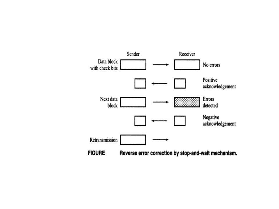
Method Reverse error correction
The reverse error correction is more economical than forward error correction in terms of the number of check bits There are three basic mechanisms of reverse error correction: Stop and wait, Go-back-N, Selective retransmission.

28
In data communication, reverse error correction method are used extensively.
The underlying principles behind these method are introduced below. Stop and wait : The sending end transmit one block of data at s time and then waits for acknowledgement from the receiver.

29
The data block contains check bits for error detection
The data block contains check bits for error detection. If the receiver detects any error in the data block, it sends a request for retransmission in the form of negative acknowledgement. If there is no error, the receiver sends a positive acknowledgement, after receiving which the sending end transmits the next block of data.

31
Go-back-N : The data blocks are numbered and the sending end keeps transmitting the data blocks with check bits. Whenever the receiver detects the error in a block, it sends a retransmission request indicating the sequence number of the data block received with errors. The sending end then starts retransmission of all the data blocks from the requested data block onwards.

33
Selective retransmission :
If the receiver is equipped with the capability of putting the received data block in sequence it requests for selective retransmission of the data block containing errors. On receipt of the request, the sending end retransmits the data block but skips the following data block already transmitted. It continues with the next data block

Similar presentations


 BEng (Essex, UK) Room 2.14.>")


>")


