Download presentation
Presentation is loading. Please wait.

1
DC Generators (ii) Lecture No 4
 Lecture No 4")
2
Armature Resistance (Ra) The resistance offered by the armature circuit is known as armature resistance (Ra) and includes: (i) resistance of armature winding. (ii) resistance of brushes The armature resistance depends upon the construction of machine.
 resistance of brushes The armature resistance depends upon the construction of machine..")
3
Types of D.C. Generators The magnetic field in a d.c. generator is normally produced by electromagnets rather than permanent magnets. Generators are generally classified according to their methods of field excitation. On this basis, d.c. generators are divided into the following two classes: (i) Separately excited d.c. generators (ii) Self-excited d.c. generators The behavior of a d.c. generator on load depends upon the method of field excitation adopted
 Separately excited d.c. generators (ii) Self-excited d.c. generators The behavior of a d.c. generator on load depends upon the method of field excitation adopted.")
4
A d.c. generator whose field magnet winding is supplied from an independent external d.c. source (e.g., a battery etc.) is called a separately excited generator. Fig. shows the connections of a separately excited generator. The voltage output depends upon the speed of rotation of armature and the field current (Vi=Kn φ). The greater the speed and field current, greater is the generated e.m.f. It may be noted that separately excited d.c. generators are rarely used in practice. The d.c. generators are normally of self-excited type
 is called a separately excited generator. Fig. shows the connections of a separately excited generator. The voltage output depends upon the speed of rotation of armature and the field current (Vi=Kn φ). The greater the speed and field current, greater is the generated e.m.f. It may be noted that separately excited d.c. generators are rarely used in practice. The d.c. generators are normally of self-excited type.")
6
As the Core of DC machine is made of ferromagnetic material, the residual magnetism exists. In ferromagnetic materials, the magnetic power increase with the increase of the current flow through coils. When current is reduced to zero, still those coils have magnetic power left in it Hence residual magnetism is used to start the machine.

9
(i) Series generator: In a series wound generator, the field winding is connected in series with armature winding so that whole armature current flows through the field winding as well as the load. Fig. shows the connections of a series wound generator. Since the field winding carries the whole of load current, it has a few turns of thick wire having low resistance. Series generators are rarely used except for special purposes e.g., as boosters.

10
Line Boosters In the days of direct current mains, voltage drop along the line was a problem so line boosters were used to correct it. Suppose that the mains voltage was 110 V. Houses near the power station would receive 110 volts but those remote from the power station might receive only 100 V so a line booster would be inserted at an appropriate point to "boost" the voltage. It consisted of a motor, connected in parallel with the mains, driving a generator, in series with the mains. The motor ran at the depleted mains voltage of 100 V and the generator added another 10 V to restore the voltage to 110 V. This was an inefficient system and was made obsolete by the development of alternating current mains, which allowed for high-voltage distribution and voltage regulation by transformers.

11
(ii) Shunt generator: In a shunt generator, the field winding is connected in parallel with the armature winding so that terminal voltage of the generator is applied across it. The shunt field winding has many turns of fine wire having high resistance. Therefore, only a part of armature current flows through shunt field winding and the rest flows through the load. Fig.. shows the connections of a shunt-wound generator.

12
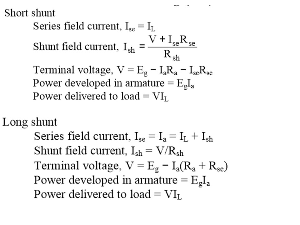
(iii) Compound generator : In a compound-wound generator, there are two sets of field windings on each pole—one is in series and the other in parallel with the armature. A compound wound generator may be: (a) Short Shunt in which only shunt field winding is in parallel with the armature winding. (b) Long Shunt in which shunt field winding is in parallel with both series field and armature winding
 Short Shunt in which only shunt field winding is in parallel with the armature winding. (b) Long Shunt in which shunt field winding is in parallel with both series field and armature winding.")
14
Losses in a D.C. Machine The losses in a d.c. machine (generator or motor) may be divided into three classes viz (i) copper losses (ii) iron or core losses and (iii) mechanical losses. All these losses appear as heat and thus raise the temperature of the machine. They also lower the efficiency of the machine. Note. There is also brush contact loss due to brush contact resistance (i.e., resistance between the surface of brush and surface of commutator). This loss is generally included in armature copper loss.
 may be divided into three classes viz (i) copper losses (ii) iron or core losses and (iii) mechanical losses. All these losses appear as heat and thus raise the temperature of the machine. They also lower the efficiency of the machine. Note. There is also brush contact loss due to brush contact resistance (i.e., resistance between the surface of brush and surface of commutator). This loss is generally included in armature copper loss..")
15
Copper losses result from Joule heating stating that the energy lost increases as the square of the current through the wire and is in proportion of the electrical resistance of the conductors. Copper Loss = I2R where I (amperes) is the current flowing in the conductor and R (ohms) the resistance of the conductor. The copper loss being represented in watts.
 is the current flowing in the conductor and R (ohms) the resistance of the conductor. The copper loss being represented in watts..")
16
In order to reduce this loss in a d.c. machine, armature core is made of such materials which have a low value of Steinmetz hysteresis co-efficient e.g., silicon steel

18
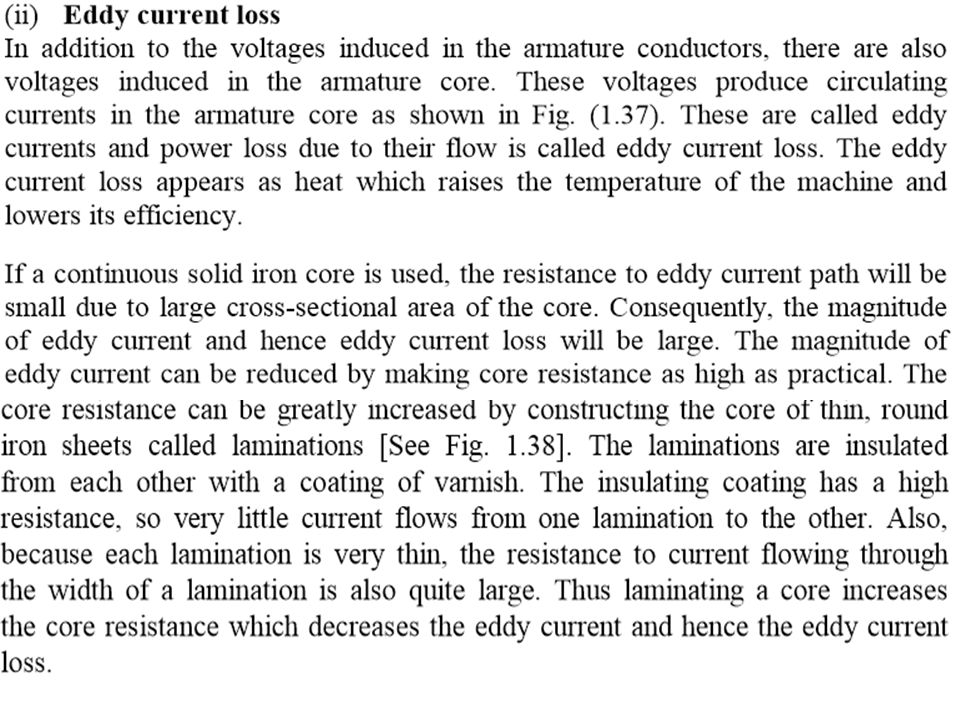
It may be noted that eddy current loss depends upon the square of lamination thickness. For this reason, lamination thickness should be kept as small as possible.

19
3. Mechanical losses These losses are due to friction and windage. (i) friction loss e.g., bearing friction, brush friction etc. (ii) windage loss i.e., air friction of rotating armature. These losses depend upon the speed of the machine. But for a given speed, they are practically constant. Note. Iron losses and mechanical losses together are called stray losses Constant and Variable Losses The losses in a d.c. generator (or d.c. motor) may be sub-divided into (i) Constant losses Those losses in a d.c. generator which remain constant at all loads are known as constant losses. The constant losses in a d.c. generator are: (a) iron losses (b) mechanical losses (ii) Variable losses Those losses in a d.c. generator which vary with load are called variable losses. The variable losses in a d.c. generator are
 friction loss e.g., bearing friction, brush friction etc. (ii) windage loss i.e., air friction of rotating armature. These losses depend upon the speed of the machine. But for a given speed, they are practically constant. Note. Iron losses and mechanical losses together are called stray losses Constant and Variable Losses The losses in a d.c. generator (or d.c. motor) may be sub-divided into (i) Constant losses Those losses in a d.c. generator which remain constant at all loads are known as constant losses. The constant losses in a d.c. generator are: (a) iron losses (b) mechanical losses (ii) Variable losses Those losses in a d.c. generator which vary with load are called variable losses. The variable losses in a d.c. generator are.")
20
Power Stages The various power stages in a d.c. generator are represented diagrammatically in Fig. A−B = Iron and friction losses B−C = Copper losses

Similar presentations


>")


 Electrical terms Electricity & magnetism Electricity Circuits Magnetism Electrical units Electric potential or eletromotive.>")