Download presentation
Presentation is loading. Please wait.

1
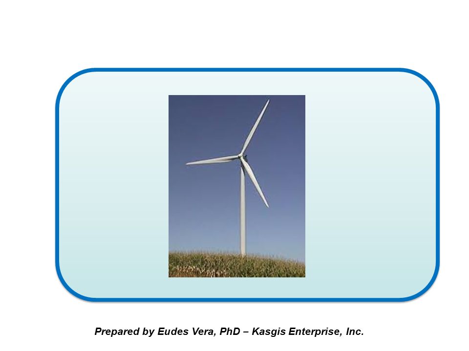
The Airflow-Powered Motor A Converter of Air Thermal Energy into Mechanical Energy Prepared by Eudes Vera, Ph.D. – Kasgis Enterprise, Inc.

2
The Airflow – Powered Motor (APM) is an aerodynamic energy conversion system capable of extracting part of the thermal energy carried by an internally accelerated airflow to convert it into a significant amount of mechanical energy which can be used to generate electricity Prepared by Eudes Vera, Ph.D. – Kasgis Enterprise, Inc.

3
The ratio of the mechanical power generated to the mechanical power applied to the system can be higher than the Betz limit of conventional wind turbines. Even ratios greater than 100% are quite possible

4
The Air Motor does not require storage of fuel and produces no contamination at all. Hence, Cost of fuel = 0 Prepared by Eudes Vera, Ph.D. – Kasgis Enterprise, Inc.

5
The most fundamental part of the airflow motor is the power generator element, that is, the Thermal Airfoil Turbine, consisting of two concentic cylinders and a number of airfoils placed over the surface of the innermost cylinder Prepared by Eudes Vera, PhD – Kasgis Enterprise, Inc.

6
A thermal airfoil turbine with 4 airfoils Prepared by Eudes Vera, PhD – Kasgis Enterprise, Inc.

7
A thermal airfoil turbine converts part of the internal energy of an airflow of velocity V φ into rotational energy on its shaft without affecting significantly the airflow velocity. In other words, input and output airflow velocities are practically the same Prepared by Eudes Vera, PhD – Kasgis Enterprise, Inc.

8
In contrast, in conventional wind turbines the blades decelerate significantly the incoming wind as they extract their rotational energy from the wind kinetic energy. Prepared by Eudes Vera, PhD – Kasgis Enterprise, Inc.

9
Downwind of conventional wind turbines moves more slowly than upwind. The winds starts to slow down even before it reaches the blades Prepared by Eudes Vera, PhD – Kasgis Enterprise, Inc.

10
In conventional wind turbines, it is not uncommon for the wind just before the turbine to lose about a third of its speed and downwind the wind speed can be reduced about two thirds Prepared by Eudes Vera, PhD – Kasgis Enterprise, Inc.

11
Conventional HAWT wind turbines are convertors of the incoming wind kinetic energy into rotational energy of the blades. The output rotational power can never exceed 59.3% of the incoming kinetic power, according to Betz’s law Prepared by Eudes Vera, PhD – Kasgis Enterprise, Inc.

13
Blades in conventional wind turbines act as obstacles to the wind whereas airfoils of thermal airfoil turbines look almost transparent to the incoming airflow so that the airflow velocity entering and outgoing the turbine remains practically the same Prepared by Eudes Vera, PhD – Kasgis Enterprise, Inc.

14
Thermal Airfoil Turbines, on the other hand, are convertors of the internal (thermal) energy of the incoming airflow into rotational energy of the airfoils. The output rotational power can be much greater than 59.3% of the kinetic power of the incoming airflow.

15
Its operation is based on the aerodynamic phenomenon that takes places when an airflow with a velocity V φ encounters the leading edge of an airfoil placed at a certain attack angle with the airflow direction Prepared by Eudes Vera, PhD – Kasgis Enterprise, Inc.

16
VV Fundamental Principle of Operation Forces acting on an aero dynamical airfoil impacted by an airflow of velocity V φ Prepared by Eudes Vera, PhD – Kasgis Enterprise, Inc.

17
VV Fundamental Principle of Operation It is well known that forces F L and F D are given by F D = C D ρ V φ 2 A p / 2 F L = C L ρ V φ 2 A p / 2 Where C D = Airfoil Drag Coefficient; C L = Airfoil Lift Coefficient; A p = Airfoil Area as seen by airflow; V φ = Airflow Velocity; ρ = Airflow density Prepared by Eudes Vera, PhD – Kasgis Enterprise, Inc.

18
VV Fundamental Principle of Operation Prepared by Eudes Vera, PhD – Kasgis Enterprise, Inc. By properly designing the airfoils and by choosing an adequate angle of attack α, it is possible to obtain that C L / C D ˃˃ 1, so that F L ˃˃ F D, which ensures a high output power

19
The Airflow-Powered Motor consists of a housing or empty chamber containing a converging (inlet )nozzle, a fan, a Venturi-like throat, a diverging (outlet) nozzle; and one or more thermal airfoil turbines that are placed within the Venturi-like throat Prepared by Eudes Vera, PhD – Kasgis Enterprise, Inc.
nozzle, a fan, a Venturi-like throat, a diverging (outlet) nozzle; and one or more thermal airfoil turbines that are placed within the Venturi-like throat Prepared by Eudes Vera, PhD – Kasgis Enterprise, Inc.")
20
VV Schematic representation of the airflow motor showing the Empty Chamber, the fan F and two thermal airfoil turbines Prepared by Eudes Vera, PhD – Kasgis Enterprise, Inc.

21
Notice that in the Airflow-Powered Motor the turbines are placed one behind the other because the airfoils do not reduce significantly the velocity of the flow. In contrast, conventional wind turbines always reduce the speed of the incoming wind and one turbine has to be tens of meters behind the other Prepared by Eudes Vera, PhD – Kasgis Enterprise, Inc.

22
The Converging Nozzle serves to accelerate the incoming airflow. The Diverging Nozzle is the machine exhaust and serves to decelerate the outgoing airflow Prepared by Eudes Vera, PhD – Kasgis Enterprise, Inc.

23
The Fan F is driven by an electric motor or a drill, and further accelerates the incoming airflow. which is going to impact the thermal airfoil turbines located in the Venturi - like throat The Fan F is driven by an electric motor or a drill, and further accelerates the incoming airflow. which is going to impact the thermal airfoil turbines located in the Venturi - like throat Prepared by Eudes Vera, PhD – Kasgis Enterprise, Inc.

24
The turbines are the actual energy converters and are formed by a number of aerodynamic airfoils placed symmetrically around a revolving cylinder Prepared by Eudes Vera, PhD – Kasgis Enterprise, Inc.

25
Aerodynamic airfoils Prepared by Eudes Vera, PhD – Kasgis Enterprise, Inc.

26
(a) A variety of an airfoil turbine having eight airfoils; b) Front view (a) (b) Prepared by Eudes Vera, PhD – Kasgis Enterprise, Inc.
 A variety of an airfoil turbine having eight airfoils; b) Front view (a) (b) Prepared by Eudes Vera, PhD – Kasgis Enterprise, Inc.")
27
A Proof of Concept Airflow Motor Prototype

28
Prepared by Eudes Vera, PhD – Kasgis Enterprise, Inc. A POC Airflow Motor Prototype consisting of two identical turbines uses the following geometric parameters: D = 50 cm; d = 32 cm; b = 8 cm; c = 26.5 cm

29
Airflow Motor, including two turbines, Converging nozzle, Fan, and Alternator to generate electric current (Diverging nozzle is not included) Prepared by Eudes Vera, PhD – Kasgis Enterprise, Inc.
 Prepared by Eudes Vera, PhD – Kasgis Enterprise, Inc.")
30
The starter or blower is simply a fan which provides an airflow in the Venturi – like passage at a certain speed V ϕ. It is well known that the mechanical power generated by the airfoils is proportional to V ϕ 3 Prepared by Eudes Vera, PhD – Kasgis Enterprise, Inc.

31
So useful power can be increased simply by increasing V ϕ. Useful power depends on the number of aerodynamic airfoils as well Prepared by Eudes Vera, PhD – Kasgis Enterprise, Inc.

32
Additionally, the useful power provided by one generator (turbine) can be duplicated if two generators are employed, or tripled if three generators are used, and so on Prepared by Eudes Vera, PhD – Kasgis Enterprise, Inc.
 can be duplicated if two generators are employed, or tripled if three generators are used, and so on Prepared by Eudes Vera, PhD – Kasgis Enterprise, Inc.")
33
Aerodynamic airfoils Prepared by Eudes Vera, PhD – Kasgis Enterprise, Inc.

34
Perspective view of an aerodynamic airfoil

35
Three views and some geometrical parameters of an airfoil Prepared by Eudes Vera, PhD – Kasgis Enterprise, Inc.

36
If the static attack angle is chosen to be about 45°, the approaching airfoil sees the airfoils at an apparent attack angle close to 0°, where the ratio C L / C D is much greater than 1. This means that airfoils are quasi – transparent to the airflow Prepared by Eudes Vera, PhD – Kasgis Enterprise, Inc.

37
The drag power and the generated power for the Airfow- powered motor are given respectively by P D = (1/2) ρ N a N s C D A p cos α V φ 3, W P G = (1/2) ρ N a N s C L A p sin α V φ 3, W Where ρ is the air density, N a is the number of airfoils, N s is the number of identical stages in the turbine placed in the Venturi – like section, α is the attack angle, A p is the airfoil planform area; V φ is the airflow velocity; and C D and C L are respectively the drag and the lift coefficients
 ρ N a N s C D A p cos α V φ 3, W P G = (1/2) ρ N a N s C L A p sin α V φ 3, W Where ρ is the air density, N a is the number of airfoils, N s is the number of identical stages in the turbine placed in the Venturi – like section, α is the attack angle, A p is the airfoil planform area; V φ is the airflow velocity; and C D and C L are respectively the drag and the lift coefficients")
38
Prepared by Eudes Vera, PhD – Kasgis Enterprise, Inc. The efficiency of a thermal airfoil turbine is defined as ղ t = (P G / P D ) And the airflow motor efficiency is defined as ղ AM = (P G / P i ) (100) Where P i is the power supplied by the fan to the airflow By proper design of the airfoils and turbine parameters, the airflow – powered motor can achieve an efficiency much greater than 1, that is, the APM can be a self sustaining device
 And the airflow motor efficiency is defined as ղ AM = (P G / P i ) (100) Where P i is the power supplied by the fan to the airflow By proper design of the airfoils and turbine parameters, the airflow – powered motor can achieve an efficiency much greater than 1, that is, the APM can be a self sustaining device.")
39
There is a range of fan’s angular velocities at which the output power from a generator is less than the power applied to the fan Prepared by Eudes Vera, PhD – Kasgis Enterprise, Inc.

40
However, as the angular velocity of the fan is increased, there appears a range of angular velocities where the output power is greater than the applied power, i.e., a power gain takes place Prepared by Eudes Vera, PhD – Kasgis Enterprise, Inc.

41
Generated power and Drag power for a low-power thermal airfoil turbine as a function of the turbine rotational velocity in rpm

42
The proof of concept airflow-powered motor prototype has two thermal airfoil turbines each having 4 airfoils, and is capable of generating 625 W of output power when operating at a fan rotational speed of 1,555 rpm while consuming only 591 W. If the airflow velocity were to be duplicated by duplicating the fan rotational speed, this prototype can generate up to 5 kW, which is sufficient to power an average household Prepared by Eudes Vera, PhD – Kasgis Enterprise, Inc.

43
If the fan is removed from the airflow motor, the latter can be used as a very efficient wind turbine. As a wind turbine if the input wind power is 591 W, the prototype built could generate 625 W, which means that this wind turbine would have an efficiency of 105.75%. No existing conventional wind turbines can achieve such a high efficiency Prepared by Eudes Vera, PhD – Kasgis Enterprise, Inc.

44
However, keep in mind that the thermal airfoil turbine is not a conventional wind turbine Prepared by Eudes Vera, PhD – Kasgis Enterprise, Inc.

45
TAT vs. HAWT The TAT converts airflow internal energy in rotational energy without affecting much the airflow velocity, whereas the HAWT converts the kinetic energy of the wind into rotational energy but affecting significantly the wind velocity

46
Prepared by Eudes Vera, PhD – Kasgis Enterprise, Inc. TAT vs. HAWT TAT’s airfoils are almost transparent to the airflow whereas HAWT’s blades are rather an obstacle to the wind flow

47
Prepared by Eudes Vera, PhD – Kasgis Enterprise, Inc. TAT vs. HAWT Large and constant static angle of attack of TAT airfoils (typically 45° - 50°) Small static angle of attack of HAWT blades
 Small static angle of attack of HAWT blades.")
48
Prepared by Eudes Vera, PhD – Kasgis Enterprise, Inc. TAT vs. HAWT TAT airfoil geometric parameters: Taper ratio λ = 1; Sweep angle = 0° HAWT blade geometric parameter: Taper ratio λ 0°

49
Prepared by Eudes Vera, PhD – Kasgis Enterprise, Inc. TAT vs. HAWT TAT predominant dimension: horizontal (Airfoil chord c is much larger than airfoil span b) HAWT predominant dimension: vertical (Blade span b is much larger than blade chord c)
 HAWT predominant dimension: vertical (Blade span b is much larger than blade chord c).")
50
The Airflow-Powered Motor requires very little maintenance (mostly periodical lubrication of bearing and cleaning of airfoils and cylinders Prepared by Eudes Vera, PhD – Kasgis Enterprise, Inc.

51
Assuming the initial cost per generated kilowatt for the Airflow-Powered Motor as 30 USD, the cost of the APM kilowatt - hour can be estimated in 0.068 cents, the lowest of current renewable energy technologies Prepared by Eudes Vera, PhD – Kasgis Enterprise, Inc.

52
Thank you! Prepared by Eudes Vera, PhD – Kasgis Enterprise, Inc.

Similar presentations


 works by capturing kinetic wind energy and converting it to electrical energy.>")
