Download presentation
Presentation is loading. Please wait.

1
See 7 RCL series a.c. circuit applet http://www.ngsir.netfirms.com/englishhtm/RLC.htm

2
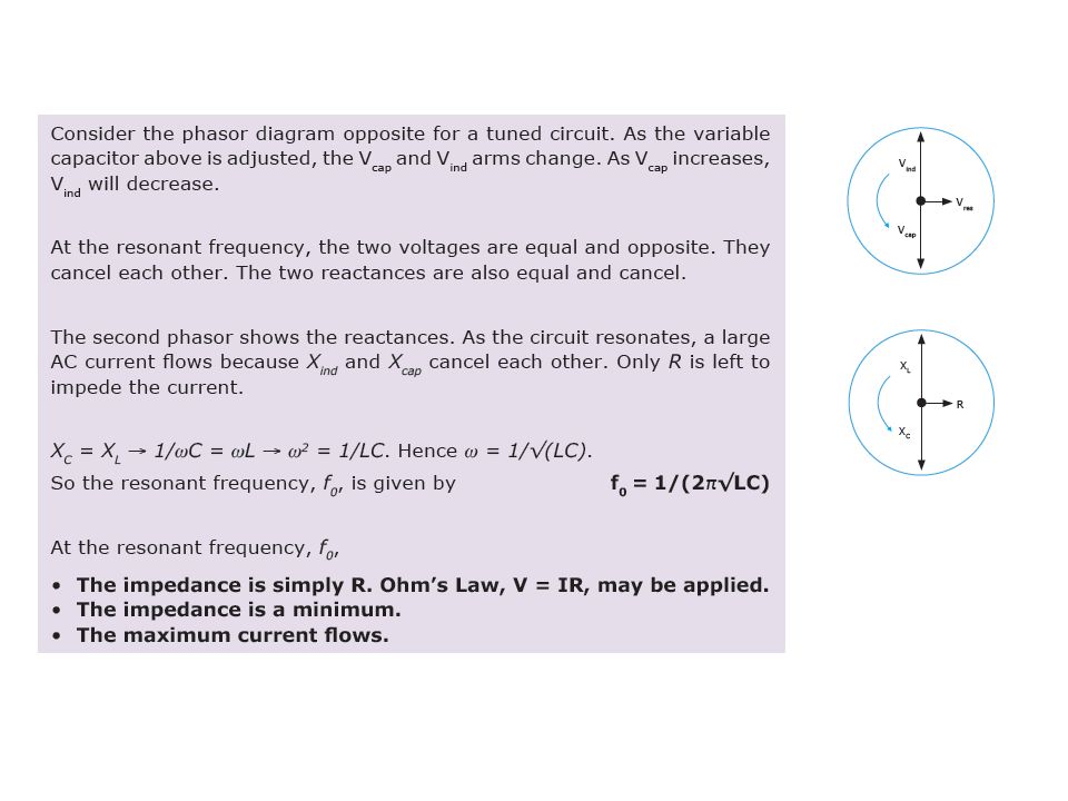
Reactance is dependant on frequency ie By altering the frequency it is possible to reach the point at which V L = V C. At this stage, Z has its smallest value (so Z = R) and the current in the circuit will be a Maximum. The frequency when this occurs is called the resonant frequency f o. At resonance:
 and the current in the circuit will be a Maximum. The frequency when this occurs is called the resonant frequency f o. At resonance:.")
4
The 12V peak voltage supply has a variable frequency. Current readings are taken every 5 Hz giving a graph of I (A) vs f (Hz) The current peaks sharply at the resonant frequency of ~ 50 Hz. V S =12V (variable f) 2H 5μF5μF 500Ω A I (A) f (Hz) I max when X L - X C =0
 vs f (Hz) The current peaks sharply at the resonant frequency of ~ 50 Hz. V S =12V (variable f) 2H 5μF5μF 500Ω A I (A) f (Hz) I max when X L - X C =0.")
5
1.Determine the resonant frequency for this circuit 2.Determine the reactance of the capacitor at this frequency 3.State the reactance of the inductor at this frequency 4.Explain, using phasors, why the circuit is at resonance 1.Determine the resonant frequency for this circuit 2.Determine the reactance of the capacitor at this frequency 3.State the reactance of the inductor at this frequency 4.Explain, using phasors, why the circuit is at resonance This LCR circuit has a 5.0 Ω resistor in series with a 250 µF capacitor and a 15 mH inductor. The AC supply is variable frequency and has a peak voltage of 6.0 V. 15 mH 250 µF 6 V variable frequency generator

6
1.Determine the resonant frequency for this circuit This LCR circuit has a 5.0 Ω resistor in series with a 250 µF capacitor and a 15 mH inductor. The AC supply is variable frequency and has a peak voltage of 6.0 V. LCR Circuits 15 mH 250 µF 6 V variable frequency generator At resonance X C = X L At resonance X C = X L

7
This LCR circuit has a 5.0 Ω resistor in series with a 250 µF capacitor and a 15 mH inductor. The AC supply is variable frequency and has a peak voltage of 6.0 V. LCR Circuits 15 mH 250 µF 6 V variable frequency generator 2.Determine the reactance of the capacitor at this frequency 3.State the reactance of the inductor at this frequency. X L = 7.7 Ω 4.Explain, using phasors, why the circuit is at resonance X L = 7.7 Ω X C = 7.7 Ω R = 5 Ω = At resonance |X C | = |X L | and the two vectors cancel

Similar presentations