Download presentation
Presentation is loading. Please wait.

2
Units to be measured and calculated VoltageVoltsV or E ResistanceOhmsR or Ω Current AmpsI or A PowerWattW or P

4
Page 61 There are no negative voltages, currents, or resistance entered into any Ohm’s Law equations! There are other principles of electricity that do take polarity into account.

5
2.8 Polarity of voltage drops page 60 The author is using electron flow. Electrons only flow in one directions.

6
Chapter 3 Home work Electrical Safety. Chapter 3 is important but not as important as chapter 5.

7
Chapter 4 SCIENTIFIC NOTATION AND METRIC PREFIXES

8
Chapter 5 will be next Subjects in blue not yet needed 5.1 What are ”series” and ”parallel” circuits?............ 129 5.2 Simple series circuits............................. 132 5.3 Simple parallel circuits........................... 139 5.4 Conductance.................................... 144 5.5 Power calculations............................... 146 5.6 Correct use of Ohm’s Law......................... 147 5.7 Component failure analysis....................... 149 5.8 Building simple resistor circuits.................... 155

9
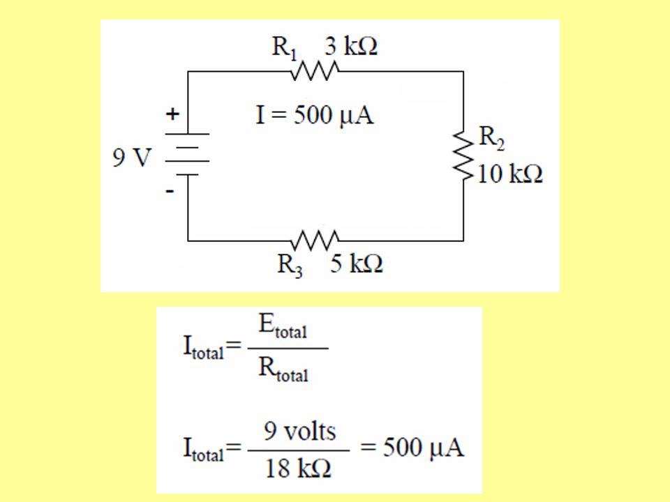
5.2 Simple series circuits The current is the same through any component in a series circuit.

10
Page 134 The values of 3k, 10k, and 5k ohms are individual quantities for individual resistors.

11
Calculating I total by calculating R total first. R total = R1 + R2 + R3 R total = 3 kΩ + 10 kΩ + 5 kΩ R total = 18 kΩ

15
Page 137 Chapter 5

16
Textbook page 148

18
V S =_____ R T =_____ I S =_____ V R1 =_____ V A =_____

19
V S = 24V R T = 10KΩ I S = 2.4mA V R1 = 14.4V V A = 9.6V

21
Watts Power

22
Vs= 12V I T =.008A P T = P R1 = P R2 =

23
V S = 12V V R1 = 8V V R2 = 4V I T =.008A

24
Vs= 12V I T =.008A P T =.008 x 12 =.096 = 96mW P R1 =.008 x 8 =.064 = 64mW P R2 =.008 x 4 =.032 = 32mW

26
R # / R T * V s = V R# R1/ RT x Vs = VR1 R2/ RT x Vs = VR2 R3/ RT x Vs = VR3

27
R T = 10 Ω

29
V S = 12V V R1 = 8V V R2 = 4V Voltage divider rule.

31
Resistance is measured “across” a device in question. R or Ω Voltage sources must be removed.

33
Lab 4 page 56 Exercise 2

34
A B C RTRT

37
Anode: the positive terminal. Cathode: the negative terminal.

38
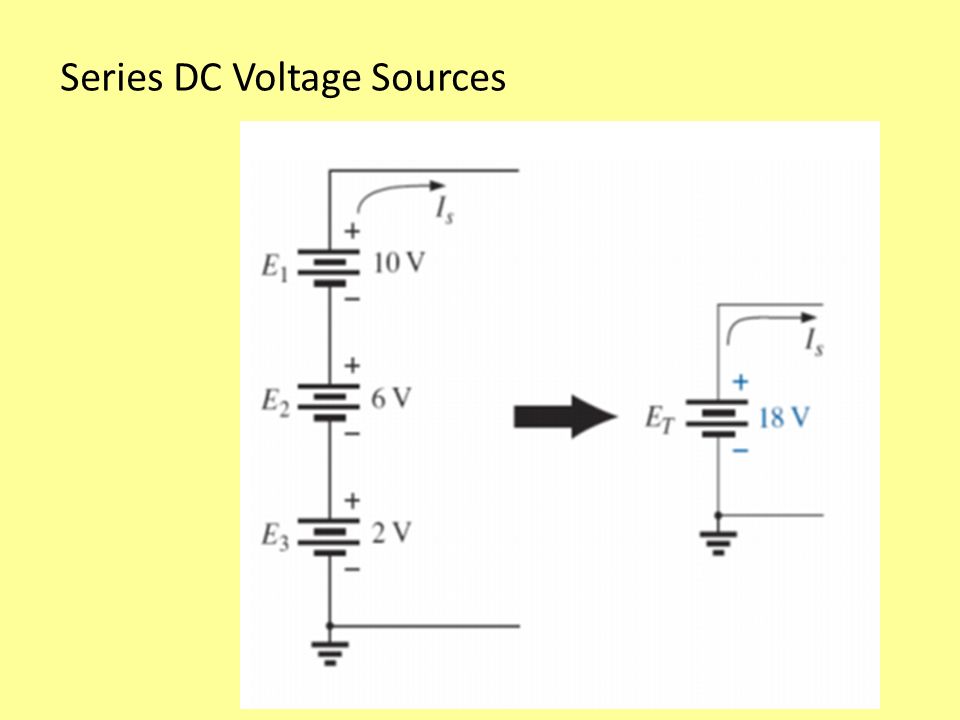
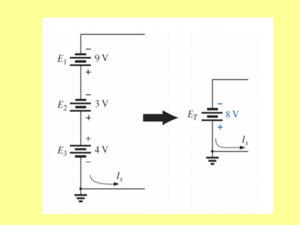
Series DC Voltage Sources The connection of batteries in series to obtain a higher voltage is common in much of today’s portable electronic equipment.

39
Series DC Voltage Sources

44
Textbook page 156

45
Know your board.

46
1. Get the resistors. 2. Measure their resistance. 3. Set and measure the voltage. 4. Connect the circuit.

47
Textbook page 157 Make the circuit layout match the schematic as much as possible. Know the breadboard layout and connections.

48
Lab/Experiment 3 Ohm’s Law

49
PLOTTING OHM’S LAW Lab/ Experiment #3

50
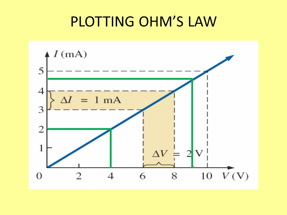
PLOTTING OHM’S LAW

52
10V /.005A = 2000Ω 4V /.002A = 2000Ω 8V – 6V /.004A -.003A = 2V /.001A = 2000Ω

53
Lab / Experiment 3 page 41 By finding the reciprocal of the resistance, we have a measure of how well the material conducts electricity. The quantity is called conductance, has the symbol G, and is measured in siemens.

54
Lab / Experiment 3 page 41 Conductance, has the symbol G, and is measured in siemens.

Similar presentations