Download presentation
Presentation is loading. Please wait.

1
1 Teaching Innovation - Entrepreneurial - Global The Centre for Technology enabled Teaching & Learning, M G I, India DTEL DTEL (Department for Technology Enhanced Learning)
")
2
DEPARTMENT OF MECHANICAL TECHNOLOGY IV-SEMESTER MECHANICS OF MATERIALS 2 UNIT NO. 2 1. Shear Force & Bending Moment 2. Bending Stresses in beams

3
CHAPTER 2:- SYLLABUSDTEL. Shear force and bending moment: - Types of beam (cantilever beam, simply supported beam, overhung beam etc.), Types of loads (Concentrated and UDL), 1 Shear force and bending moment diagrams for different types of beams subjected to different types of loads 2 shear force and bending moment diagrams for beams subjected to couple, Relation between load, shear force and bending moment. 3 3 Stresses in beams: - Pure bending, theory of simple bending with assumptions & expressions for bending stress, derivation of bending equation 4 Bending stresses in symmetrical sections, section modulus for various shapes of beam sections. 5
, Types of loads (Concentrated and UDL), 1 Shear force and bending moment diagrams for different types of beams subjected to different types of loads 2 shear force and bending moment diagrams for beams subjected to couple, Relation between load, shear force and bending moment. 3 3 Stresses in beams: - Pure bending, theory of simple bending with assumptions & expressions for bending stress, derivation of bending equation 4 Bending stresses in symmetrical sections, section modulus for various shapes of beam sections. 5.")
4
CHAPTER-2 SPECIFIC OBJECTIVE / COURSE OUTCOMEDTEL Understand and solve simple problems involving stresses and strain in two and three dimensions. 1 To draw shear force and bending moment diagrams of simple beams and understand the relationships between loading intensity, shearing force and bending moment 2 4 The student will be able to: Compute the bending stresses in beams with one or two materials. 3 Understand special cases of unsymmetrical bending and members made of composite materials 4 Understand curved members, stress concentrations, inelastic bending, and residual stresses 5

5
DTEL Introduction 5 5 LECTURE 1:- Chapter 5: Torsion Devoted to the analysis and the design of beams Beams – usually long, straight prismatic members In most cases – load are perpendicular to the axis of the beam Transverse loading causes only bending (M) and shear (V) in beam Span, L Distributed Load, w(x) Concentrated Load, P Longitudinal Axis Fig 2.1 Types of Load in Beam
 and shear (V) in beam Span, L Distributed Load, w(x) Concentrated Load, P Longitudinal Axis Fig 2.1 Types of Load in Beam")
6
DTEL Types of Load and Beam 6 6 Chapter 5: Torsion The transverse loading of beam may consist of Concentrated loads, P1, P2, unit (N) Distributed loads, w, unit (N/m) Fig 2.2 Types of Loads LECTURE 1:-
 Distributed loads, w, unit (N/m) Fig 2.2 Types of Loads LECTURE 1:-")
7
DTEL Types of Load and Beam 7 7 Chapter 5: Torsion Beams are classified to the way they are supported Several types of beams are shown below L shown in various parts in figure is called ‘span’ Fig 2.3 Types of Beams LECTURE 1:-

8
DTEL Definitions 8 8 Shear Force and Bending Moment Shear Force: is the algebraic sum of the vertical forces acting to the left or right of the cut section Bending Moment: is the algebraic sum of the moment of the forces to the left or to the right of the section taken about the section LECTURE 1:-

9
DTEL S. F & B. M. Diagrams 9 9 Shear Force (SF) diagram – The Shear Force (V) plotted against distance x Measured from end of the beam Bending moment (BM) diagram – Bending moment (BM) plotted against distance x Measured from end of the beam Fig 2.4 SFD & BMD LECTURE 1:-
 diagram – The Shear Force (V) plotted against distance x Measured from end of the beam Bending moment (BM) diagram – Bending moment (BM) plotted against distance x Measured from end of the beam Fig 2.4 SFD & BMD LECTURE 1:-.")
10
DTEL 10 THANK YOU

11
DTEL Determination of SF & BM 11 The Shear & bending moment diagram will be obtained by determining the values of V and M at selected points of the beam Fig 2.5 Determination of SF & BM LECTURE 2:-

12
DTEL Determination of SF & BM 12 The Shear V & bending moment M at a given point of a beam are said to be positive when the internal forces and couples acting on each portion of the beam are directed as shown in figure below The shear at any given point of a beam is positive when the external forces (loads and reactions) acting on the beam tend to shear off the beam at that point as indicated in figure below Fig 2.6 (a) (b) Effect of internal & external forces LECTURE 2:-
 acting on the beam tend to shear off the beam at that point as indicated in figure below Fig 2.6 (a) (b) Effect of internal & external forces LECTURE 2:-")
13
DTEL Determination of SF & BM 13 The bending moment at any given point of a beam is positive when the external forces (loads and reactions) acting on the beam tend to bend the beam at that point as indicated in figure below : LECTURE 2:- Fig. 2.7

14
DTEL Sign Convention 14 Shear & Moment Sign Convention The signs associated with the shear force and bending moment are defined in a different manner than the signs associated with forces and moments in static equilibrium. The Shear Force is positive if it tends to rotate the beam section clockwise with respect to a point inside the beam section. The Bending Moment is positive if it tends to bend the beam section concave facing upward. (Or if it tends to put the top of the beam into compression and the bottom of the beam into tension.) + shear + moment Fig 2.8 Sign convention LECTURE 2:-
 + shear + moment Fig 2.8 Sign convention LECTURE 2:-.")
15
DTEL Numericals 15 Problem 1 : Draw the shear force and bending moment diagram for the following beam: Solution : Step 1: Find the reaction forces at A and D. Draw F.B.D.: ∑ Fx = 0, Ax = 0 ∑ MA = 0, (20 kips)(6 ft) + (12 kips)(14 ft) + (1.5 kips/ft)(8 ft)(28ft) – (Dy)(24 ft) = 0 Dy = 26 kips ∑ Fy = 0, Ay + Dy – 20 kips – 12 kips – (1.5 kips/ft)(8 ft) = 0, Ay = 18 kips LECTURE 2:- Fig. 2.9
(6 ft) + (12 kips)(14 ft) + (1.5 kips/ft)(8 ft)(28ft) – (Dy)(24 ft) = 0 Dy = 26 kips ∑ Fy = 0, Ay + Dy – 20 kips – 12 kips – (1.5 kips/ft)(8 ft) = 0, Ay = 18 kips LECTURE 2:- Fig")
16
DTEL Numericals 16 Construction of the Shear Force & Bending Moment diagram : LECTURE 2:- Fig. 2.10

17
DTEL Numericals 17 a)M = 0 at point A because it is pinned end with no applied bending moment. b)MB = Ma + (the area under the shear force diagram between A and B.) c)MB = 0 + (18 kips)(6 ft) = 108 kip-ft d)MC = MB + (the area under the shear force diagram between B and C.) e)MC = 108 kip-ft - (2 kips)(8 ft) = 92 kip-ft f)MD = MC + (the area under the shear force diagram between C and D.) g)MD = 92 kip-ft - (14 kips)(10 ft) = -48 kip-ft h)ME = MD + (the area under the shear force diagram between D and E.) i)ME = -48 kip-ft + 1/2 (12 kips)(8 ft) = 0 kip-ft (as expected) LECTURE 2:-
MB = Ma + (the area under the shear force diagram between A and B.) c)MB = 0 + (18 kips)(6 ft) = 108 kip-ft d)MC = MB + (the area under the shear force diagram between B and C.) e)MC = 108 kip-ft - (2 kips)(8 ft) = 92 kip-ft f)MD = MC + (the area under the shear force diagram between C and D.) g)MD = 92 kip-ft - (14 kips)(10 ft) = -48 kip-ft h)ME = MD + (the area under the shear force diagram between D and E.) i)ME = -48 kip-ft + 1/2 (12 kips)(8 ft) = 0 kip-ft (as expected) LECTURE 2:-.")
18
DTEL 18 THANK YOU

19
DTEL Numericals 19 Problem 2 : Draw Shear & Moment diagrams for the following beam 3 m1 m 12 kN 8 kN A C B D R A = 7 kN R C = 13 kN LECTURE 3:- Fig. 2.11

20
DTEL Numericals 20 3 m1 m 12 kN A C B D V (kN) M (kN-m) 7 -5 8 8 kN 7 -15 8 7 -8 2.4 m LECTURE 3:- Fig. 2.12

21
DTEL Assumptions 21 Problem 3 : Draw the shear and moment diagrams for beam shown below. LECTURE 3:- Fig. 2.13

22
DTEL Assumptions 22 Support reactions: Shown in free-body diagram. Shear and moment functions Since there is a discontinuity of distributed load and a concentrated load at beam’s center, two regions of x must be considered. 0 ≤ x 1 ≤ 5 m, +↑ F y = 0;...V = 5.75 N + M = 0;...M = (5.75x 1 + 80) kN·m LECTURE 3:- Fig. 2.14
 kN·m LECTURE 3:- Fig")
23
DTEL Assumptions 23 Shear and moment functions 5 m ≤ x 2 ≤ 10 m, +↑ F y = 0;...V = (15.75 5x 2 ) kN + M = 0;...M = ( 5.75x 2 2 + 15.75x 2 +92.5) kN·m Check results by applying w = dV/dx and V = dM/dx. LECTURE 3:- Fig. 2.15

24
DTEL Numericals 24 Shear and moment diagrams LECTURE 3:- Fig. 2.16

25
DTEL 25 THANK YOU

26
DTEL Numericals 26 Problem 4 : LECTURE 4:- Fig. 2.17

27
Solution : Find R A and R B Fy = 0 i.e. R A + R B = (1.8 x 2.6) + 4 kN = 8.68 kN MB = 0 i.e. - 4 R A + 2.4 x 4 + ( 1.8 x 2.6) x ( 4 - 1.3 ) = 0 4 R A = 9.6 + 12.63 = 22.23; R A = 5.56 kN R B = 8.68 - 5.56 = 3.12 kN DTEL Numericals 27 LECTURE 4:-
 x ( ) = 0 4 R A = = 22.23; R A = 5.56 kN R B = = 3.12 kN DTEL Numericals 27 LECTURE 4:-.")
28
DTEL Numericals 28 LECTURE 4:-

29
Shear Force & Bending Moment Diagrams DTEL Numericals 29 LECTURE 4:-

30
DTEL 30 THANK YOU

31
Problem 2 : The shaft is supported by a smooth thrust load at A and smooth journal bearing at D. If the shaft has the cross section shown, determine the absolute maximum bending stress on the shaft DTEL Numericals 31 LECTURE 5:- Fig. 2.18

32
Draw the shear and moment diagramExternal Forces Absolute Bending Stress M max = 2.25kNm DTEL Numericals 32 LECTURE 5:- Fig. 2.19

33
DTEL 33 THANK YOU

34
DTEL 34 Bending stresses in Beams LECTURE 6:-

35
DTEL Bending of Beams 35 It is important to distinguish between pure bending and non- uniform bending. Pure bending is the deformation of the beam under a constant bending moment. Therefore, pure bending occurs only in regions of a beam where the shear force is zero, because V = dM/dx. Non-uniform bending is deformation in the presence of shear forces, and bending moment changes along the axis of the beam. Fig 2.20 Theory of bending LECTURE 6:-

36
Assumptions in Simple Bending Theory (i)Beams are initially straight (ii)The material is homogenous and isotropic i.e. it has a uniform composition and its mechanical properties are the same in all directions (iii)The stress-strain relationship is linear and elastic (iv)Young’s Modulus is the same in tension as in compression (v)Sections are symmetrical about the plane of bending DTEL Assumptions 36 LECTURE 6:-
The stress-strain relationship is linear and elastic (iv)Young’s Modulus is the same in tension as in compression (v)Sections are symmetrical about the plane of bending DTEL Assumptions 36 LECTURE 6:-.")
37
Assumptions in Simple Bending Theory Contd. Sections which are plane before bending remain plane after bending. The last assumption implies that each section rotates during bending about a neutral axis, so that the distribution of strain across the section is linear, with zero strain at the neutral axis. The beam is thus divided into tensile and compressive zones separated by a neutral surface. The theory gives very accurate results for stresses and deformations for most practical beams provided that deformations are small. DTEL Assumptions 37 LECTURE 6:-

38
Theory of Simple Bending Consider an initially straight beam, AB under pure bending. The beam may be assumed to be composed of an infinite number of longitudinal fibers. Due to the bending, fibres in the lower part of the beam extend and those in the upper parts are shortened. Somewhere in-between, there would be a layer of fibre that has undergone no extension or change in length. This layer is called neutral surface. The line of intersection of the neutral surface with the cross-section is called Neutral Axis of the cross section. DTEL Simple Bending 38 LECTURE 6:-

39
DTEL Simple Bending 39 Fig 2.21 Bending shows the radius of curvature LECTURE 6:-

40
Bending deformation of a straight member Observation: - bottom line : longer - top line: shorter - Middle line: remain the same but rotate (neutral line) DTEL Bending Stresses 40 Fig 2.22 Bending stresses before & after deformation LECTURE 6:-
 DTEL Bending Stresses 40 Fig 2.22 Bending stresses before & after deformation LECTURE 6:-")
41
Strain Before deformation After deformation, Dx has a radius of curvature r, with center of curvature at point O’ Similarly Therefore DTEL Bending Stresses 41 Fig 2.23 Elements before & after deformation LECTURE 6:-

42
Maximum strain will be -ve: compressive state +ve: tension DTEL Bending Stresses 42 Fig 2.24 Normal strain distribution LECTURE 6:-

43
DTEL 43 THANK YOU

44
The Flexure Formula The location of neutral axis is when the resultant force of the tension and compression is equal to zero. Noting DTEL Flexure Formula 44 LECTURE 7:- Fig. 2.25

45
Since, therefore Therefore, the neutral axis should be the centroidal axis DTEL Flexure Formula 45 LECTURE 7:- Fig. 2.26

46
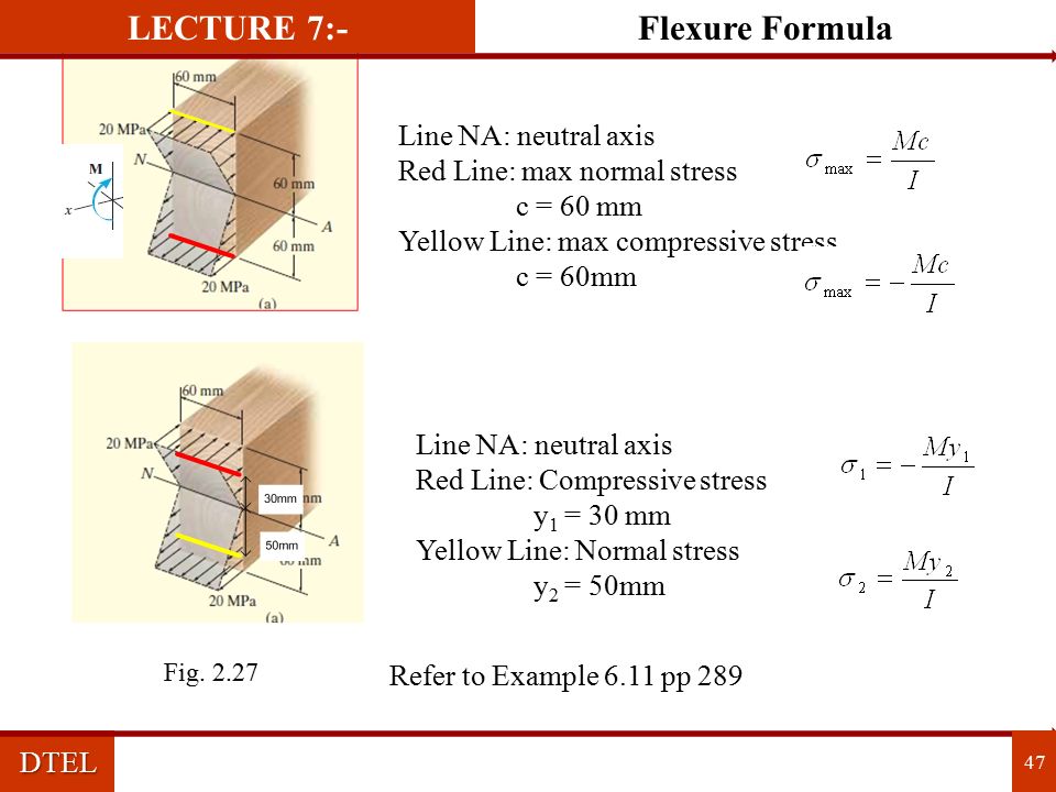
Maximum normal stress Normal stress at y distance DTEL Flexure Formula 46 LECTURE 7:-

47
Line NA: neutral axis Red Line: max normal stress c = 60 mm Yellow Line: max compressive stress c = 60mm Line NA: neutral axis Red Line: Compressive stress y 1 = 30 mm Yellow Line: Normal stress y 2 = 50mm Refer to Example 6.11 pp 289 DTEL 47 Flexure FormulaLECTURE 7:- Fig. 2.27
48
DTEL 48 THANK YOU

49
I: moment of inertial of the cross sectional area Find the stresses at A and B DTEL Moment of Inertia 49 LECTURE 8:- Fig. 2.28

50
Locate the centroid (coincide with neutral axis) DTEL Numericals on Moment of Inertia 50 LECTURE 8:- Fig. 2.29

51
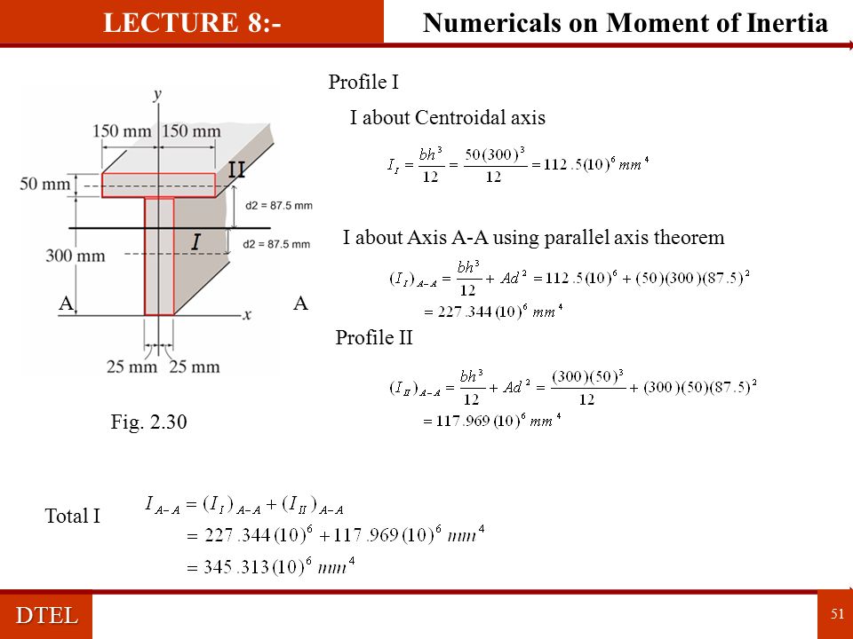
Profile I AA I about Centroidal axis I about Axis A-A using parallel axis theorem Profile II Total I DTEL Numericals on Moment of Inertia 51 LECTURE 8:- Fig. 2.30
52
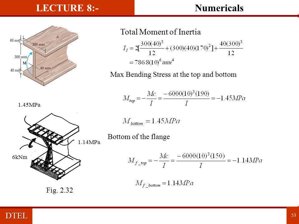
Problem : If the moment acting on the cross section of the beam is M = 6 kNm, determine the maximum bending stress on in the beam. Sketch a three dimensional of the stress distribution acting over the cross section. If M = 6 kNm, determine the resultant force the bending stress produces on the top board A of the beam DTEL Numericals 52 LECTURE 8:- Fig. 2.31

53
Total Moment of Inertia Max Bending Stress at the top and bottom Bottom of the flange 1.45MPa 1.14MPa 6kNm DTEL Numericals 53 LECTURE 8:- Fig. 2.32
54
Resultant F = volume of the trapezoid 1.45MPa 1.14MPa 40 mm 300 mm DTEL Numericals 54 LECTURE 8:- Fig. 2.33

55
DTEL 55 THANK YOU

56
DTEL References Books: 1) Strength of Materials – Prof. R. K. Rajput 2) Strength of Materials – Prof R. Ramamruttham 3) Strength of Materials – Prof. R. S. Khurmi 4) Elements of Strength of Materials, S. Timoshenko and O.H.Young, 5) Strength of Materials, R K Bansal, 6) Strength of Materials, S S Rattan, 7) Strength of Material, Ferdinard L. Singer, Harper and Row, 56
 Strength of Materials – Prof R. Ramamruttham 3) Strength of Materials – Prof. R. S. Khurmi 4) Elements of Strength of Materials, S. Timoshenko and O.H.Young, 5) Strength of Materials, R K Bansal, 6) Strength of Materials, S S Rattan, 7) Strength of Material, Ferdinard L. Singer, Harper and Row, 56.")
Similar presentations


 Spring 2008 Dr. Konstantinos A. Sierros.>")


 MAE 314 – Solid Mechanics Yun Jing Beams: Pure Bending.>")
 Chapter 2: Shear Force and Bending Moment>")


