Download presentation
Presentation is loading. Please wait.

1
Frame Relay

2
Why to use Frame Relay? Frame Relay is a virtual-circuit technology that provides low-level (physical and data link layer) service in response to the following demands:- Higher Data Rate at Lower Cost Bursty Data Less Overhead Due to Improved Transmission Media
 service in response to the following demands:- Higher Data Rate at Lower Cost Bursty Data Less Overhead Due to Improved Transmission Media.")
3
Bursty Data Some services offered by WAN providers assume that user has a fixed-rate need. For example, aT-1 line is designed for a user who wants to use the line at a consistent 1.544 Mbps. This type of service is not suitable for the many users today that need to send bursty data. For example, a user may want to send data at 6 Mbps for 2 seconds, 0 Mbps (nothing) for 7 seconds, and 3.44 Mbps for 1 second for a total of 15.44 Megabits during a period of 10 seconds. Although, the average data rate is still 1.544 Mbps, the T-1 line can not accept this type of demand because it is designed for fixed-rate data, not bursty data. Bursty data requires what is called bandwidth on demand. 0 1 2 3 4 5 6 7 8 9 10 Data Rate 1.544 Mbps Total data sent: 15.44 Megabits Fig. Fixed-rate data 0 1 2 3 4 5 6 7 8 9 10 Data Rate Total data sent: 15.44 Megabits Fig. Bursty data 6 Mbps 3.44 Mbps Seconds 12 Megabits
 for 7 seconds, and 3.44 Mbps for 1 second for a total of Megabits during a period of 10 seconds. Although, the average data rate is still Mbps, the T-1 line can not accept this type of demand because it is designed for fixed-rate data, not bursty data. Bursty data requires what is called bandwidth on demand Data Rate Mbps Total data sent: Megabits Fig. Fixed-rate data Data Rate Total data sent: Megabits Fig. Bursty data 6 Mbps 3.44 Mbps Seconds 12 Megabits.")
4
Frame Relay Frame relay is a fast, connection-oriented, packet- switching technology (based on the older X.25 packet switching technology) originally intended for use in ISDN networks, but now widely used in a variety of local and wide area networks. It can be used, for example, to interconnect local area networks. Unlike X.25, frame relay is purely a data-link layer protocol, and does not provide error handling or flow control. When an error is detected in a frame, it is dropped. Upper layer protocols are responsible for detecting and retransmitting dropped frames.

5
The devices attached to a frame relay network are either DTEs (data terminating equipment), typically located on customer premises (for example, computer terminals, routers, and bridges), and DCEs (data circuit-terminating equipment), which are carrier-owned internetworking devices that provide network switching services (usually packet switches). The diagram below shows the relationship between these devices

7
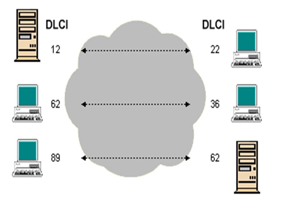
A virtual circuit (which can be either switched or permanent) must be established between two end points before data can be transferred. Each virtual circuit is uniquely identified by a data-link connection identifier (DLCI), typically assigned by the frame relay service provider. A number of virtual circuits can be multiplexed onto a single physical circuit, and a single virtual circuit can pass through any number of packet switching nodes. For switched circuits, there will be the additional overhead of call setup and termination. Establishing, maintaining and terminating a switched virtual circuit involves the same signaling protocols as are used in ISDN. Permanent virtual circuits may be established for frequent data transfers, and do not require call setup and termination.
, typically assigned by the frame relay service provider. A number of virtual circuits can be multiplexed onto a single physical circuit, and a single virtual circuit can pass through any number of packet switching nodes. For switched circuits, there will be the additional overhead of call setup and termination. Establishing, maintaining and terminating a switched virtual circuit involves the same signaling protocols as are used in ISDN. Permanent virtual circuits may be established for frequent data transfers, and do not require call setup and termination..")
9
Frame Relay Layers Simplified core Functions of Data link layer Data Link ANSI Standards Physical Frame Relay operates only at the Physical and data link layers Frame Relay has only physical and data link layers.

10
Physical and Data Link Layer Physical Layer: - No specific protocol is defined for the physical layer in Frame relay. Instead, it is left to the implementer to use whatever is available. Frame relay supports any of the protocols recognized by ANSI. Data Link Layer: - At the data link layer, Frame Relay employs a simplified version of HDLC called core LAPF. The simplifier version is used because HDLC provides extensive error and flow control fields that are not needed in Frame Relay.

11
Frame Format

12
Frame Format (continued) Flag: An eight-bit binary sequence (01111110) that indicates the start of the data frame Address: Two to four bytes that contain several pieces of Frame Relay information Ether type: Identifies the type of higher-layer protocol being encapsulated (IP, IPX, or AppleTalk) Data: A variable-length field that contains the information from the higher layers encapsulated in the Frame Relay frame
 Flag: An eight-bit binary sequence ( ) that indicates the start of the data frame Address: Two to four bytes that contain several pieces of Frame Relay information Ether type: Identifies the type of higher-layer protocol being encapsulated (IP, IPX, or AppleTalk) Data: A variable-length field that contains the information from the higher layers encapsulated in the Frame Relay frame")
13
Frame Format (continued) FCS: Frame check sequence (FCS) or cyclical redundancy check (CRC) used to ensure that the frame was not corrupted during transmission Flag: An eight-bit binary sequence (01111110) that indicates the end of the data frame Frame Relay Address Field descriptions – CR: A command or response bit that is used for sending connection management and frame acknowledgment information between stations – FECN: Setting used to alert receiving devices if the frame experiences congestion
 FCS: Frame check sequence (FCS) or cyclical redundancy check (CRC) used to ensure that the frame was not corrupted during transmission Flag: An eight-bit binary sequence ( ) that indicates the end of the data frame Frame Relay Address Field descriptions – CR: A command or response bit that is used for sending connection management and frame acknowledgment information between stations – FECN: Setting used to alert receiving devices if the frame experiences congestion")
14
Frame Format (continued) Frame Relay Address Field descriptions (continued) – BECN: Setting used on frames traveling away from the congested area to warn source devices that congestion has occurred on that path – DE: Discard eligible bit that is used to identify frames that are first to be dropped when the CIR is exceeded – EA: Extension address bits that are used to extend the Address field from two bytes to either three or four bytes
 Frame Relay Address Field descriptions (continued) – BECN: Setting used on frames traveling away from the congested area to warn source devices that congestion has occurred on that path – DE: Discard eligible bit that is used to identify frames that are first to be dropped when the CIR is exceeded – EA: Extension address bits that are used to extend the Address field from two bytes to either three or four bytes")
15
Congestion-Control Mechanisms Frame relay implements simple congestion-control mechanisms, each of which uses a single bit subfield within the Address field of the frame relay frame. Frame Relay implements two congestion- notification mechanisms: (1)Forward-explicit congestion notification (FECN) (2)Backward-explicit congestion notification (BECN)
Forward-explicit congestion notification (FECN) (2)Backward-explicit congestion notification (BECN).")
16
FECN If the network is congested, packet switching nodes will set the forward-explicit congestion notification (FECN) bit to 1 in each frame received. The destination DTE device passes this information to a higher-layer protocol, which may either initiate flow control or ignore it.

17
BECN Packet switching nodes will set the backward- explicit congestion notification (BECN) bit to 1 in frames travelling in the reverse path of frames with their FECN bit set, to inform the receiving DTE device that a particular path through the network is congested.
 bit to 1 in frames travelling in the reverse path of frames with their FECN bit set, to inform the receiving DTE device that a particular path through the network is congested.")
18
Again, the DTE device passes this information to a higher-layer protocol, which may either initiate flow control or ignore it. The discard eligibility (DE) bit can be set to 1 to identify low-priority traffic that can be dropped during periods of network congestion.
 bit can be set to 1 to identify low-priority traffic that can be dropped during periods of network congestion..")
19
Similarities between the frame relay and ATM They are virtual circuit based. They are NBMA technologies. They have burst rate features. They have congestion avoidance techniques. They have traffic shaping or management techniques. FECN of frame relay is equivalent to the EFCI of ATM. BECN of frame relay is equivalent to the RRM of the ATM.

20
Differences between frame relay and ATM Frame relay is not cell based while ATM is cell based. Frame relay is not asynchronous while ATM is asynchronous. Frame relay does not have a LANE deployment while ATM does.

21
Comparison of X.25 and Frame Relay

22
NDSL, Chang Gung University22 Comparison of X.25 and Frame Relay Protocol Stacks

23
FeatureX.25Frame Relay Connection establishment At the Network LayerNone Flow Control and Error Control At the Data Link LayerNone End-to-end flow control and error control At the Network LayerNone Data rateFixedBursty MultiplexingAt the Network LayerAt the Data Link Layer Congestion ControlNot necessaryNecessary

24
Advantages Frame relay has several advantages over comparable WAN’s such as X.25 and T-Lines :- 1.Frame Relay operates at higher speed (1.544 Mbps and recently 44.376 Mbps) 2.Frame Relay allows bursty data. Users do not have to adhere to a fixed data rate as in the case of X.25 or T-Lines. 3.Frame Relay allows a frame size of 9000 bytes, which can accommodate all LAN frames. 4.Not Costly 5.Frame Relay operates in just the physical and data link layers. This means it easily can be used as a backbone network to provide services to protocols that already have a network layer protocol. For example, the TCP/IP protocol already has network layer so if we use X.25 which has its own network layer so in results duplication of network layer but this is not the case when we used Frame Relay.

25
Disadvantages Frame Relay is not perfect. Despite its low cost, there are some disadvantages: - – Although some Frame Relay networks operate at 44.376 Mbps, this is still not high enough for protocols with even higher data rates (such as B-ISDN). – Frame Relay allows variable-length frames. This may create varying delays for different users. – Because of the varying delays, which are not under user control, Frame Relay is not suitable for sending delay sensitive data such as real-time voice or video. For example, Frame Relay is not suitable for teleconferencing.
. – Frame Relay allows variable-length frames. This may create varying delays for different users. – Because of the varying delays, which are not under user control, Frame Relay is not suitable for sending delay sensitive data such as real-time voice or video. For example, Frame Relay is not suitable for teleconferencing..")
Similar presentations